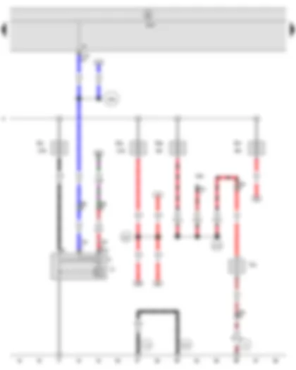
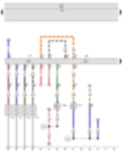
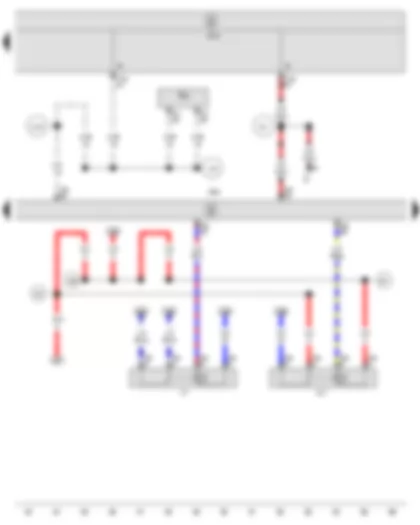
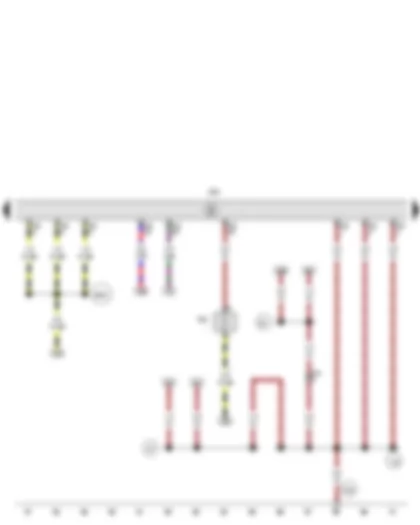
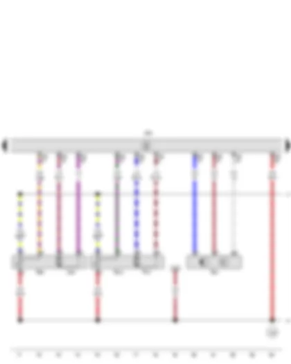
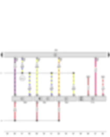
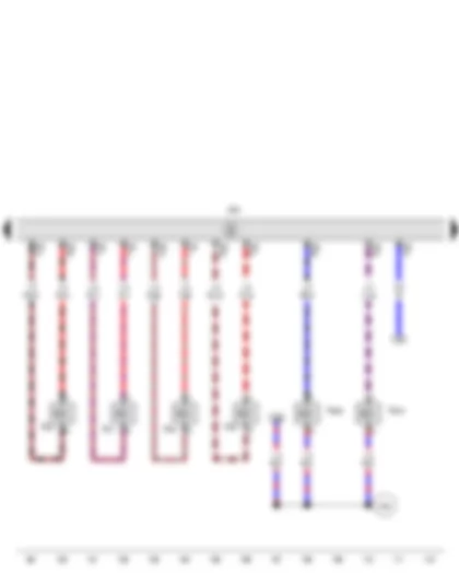
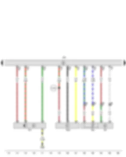
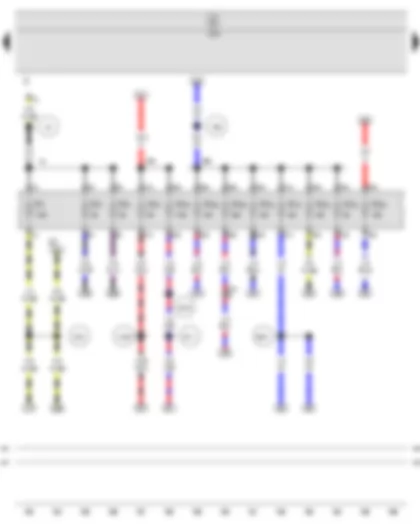
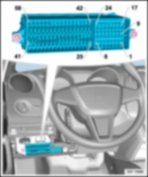
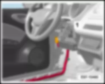
| No. | | Current Flow Diagram designation | Nominal value | | Function/component | Terminal |
| 1 | - | Fuse 1 on fuse holder C -SC1- | 7.5 A | - | Power steering control unit -J500- | 15a |
| | | | | | Heater element for crankcase breather -N79- (BXW) | |
| 2 | - | Fuse 2 on fuse holder C -SC2- | 10 A | - | Heater/heat output switch -E16- | 15a |
| | | | | | High pressure sender -G65- | |
| | | | | | Climatronic control unit -J255- | |
| | | | | | Control unit in dash panel insert -J285- | |
| | | | | | Radiator fan control unit -J293- | |
| | | | | | Air conditioning system control unit -J301- | |
| | | | | | Navigation system interface -R94- | |
| | | | | | Automatic anti-dazzle interior mirror -Y7- | |
| 3 | - | Fuse 3 on fuse holder C -SC3- | 5 A | - | Air mass meter -G70- (BLS, BMS and BXJ) | 15a |
| | | | | | Fuel pump relay -J17- (BTS, BXW, BZG, CEKA and CGPA) | |
| | | | | | Current supply relay for Simos control unit -J363- (BZG and CGPA) | |
| | | | | | Engine control unit -J623- (BLS, BMS, BTS, BXJ, BXW, BZG, CEKA and CGPA) | |
| 4 | - | Fuse 4 on fuse holder C -SC4- | 10 A | - | Steering angle sender -G85- | 15a |
| | | | | | ABS control unit -J104- | |
| 5 | - | Fuse 5 on fuse holder C -SC5- | 10 A | - | Reversing light switch -F4- | 15a |
| | | | | | Left washer jet heater element -Z20- | |
| | | | | | Right washer jet heater element -Z21- | |
| 6 | - | Fuse 6 on fuse holder C -SC6- | 10 A | - | Diagnosis connection (T16) | 15a |
| 7 | - | Fuse 7 on fuse holder C -SC7- | 5 A | - | Airbag control unit -J234- | 15a |
| 8 | - | Fuse 8 on fuse holder C -SC8- | 10 A | - | Additional coolant pump relay -J496- (CAVE and CAVF) | 87a |
| | | | | | Injector, cylinder 1 -N30- (BTS, BXW and CEKA) | |
| | | | | | Injector, cylinder 2 -N31- (BTS, BXW and CEKA) | |
| | | | | | Injector, cylinder 3 -N32- (BTS, BXW and CEKA) | |
| | | | | | Injector, cylinder 4 -N33- (BTS, BXW and CEKA) | |
| | | | | | Charge pressure control solenoid valve -N75- (CAVE and CAVF) | |
| | | | | | Activated charcoal filter solenoid valve 1 -N80- (CAVE and CAVF) | |
| | | | | | Inlet camshaft control valve 1 -N205- (CAVE and CAVF) | |
| | | | | | Turbocharger air recirculation valve -N249- (CAVE and CAVF) | |
| | | | | | Magnetic clutch for supercharger -N421- (CAVE and CAVF) | |
| 9 | - | Fuse 9 on fuse holder C -SC9- | 10 A | - | Intermittent wiper switch -E22- | 15a |
| | | | | | Rear wiper switch -E34- | |
| | | | | | Intermittent wiper regulator -E38- | |
| | | | | | Washer pump switch (automatic wash/wipe and headlight washer system) -E44- | |
| 10 | - | Fuse 10 on fuse holder C -SC10- | 5 A | - | Cruise control system switch -E45- (for models with 2 and 4-door vehicle only) | 15a |
| | | | | | Clutch pedal switch -F36- (BTS, BXW, BZG, CEKA and CGPA) | |
| | | | | | Brake pedal position sender -G100- | |
| | | | | | Fuel pump control unit -J538- (CAVE and CAVF) | |
| | | | | | Engine control unit -J623- (CAVE and CAVF) | |
| 11 | - | Fuse 11 on fuse holder C -SC11- | - | - | vacant | |
| 12 | - | Fuse 12 on fuse holder C -SC12- | 10 A | - | Multifunction steering wheel control unit -J453- (BTS, CAVE and CAVF) | 15a |
| | | | | | Mechatronic unit for dual clutch gearbox -J743- (BTS, CAVE and CAVF) | |
| 13 | - | Fuse 13 on fuse holder C -SC13- | 5 A | - | Dipped headlight control unit, on/off -J665- | 15a |
| 14 | - | Fuse 14 on fuse holder C -SC14- | - | - | vacant | |
| 15 | - | Fuse 15 on fuse holder C -SC15- | - | - | vacant | |
| 16 | - | Fuse 16 on fuse holder C -SC16- | - | - | vacant | |
| 17 | - | Fuse 17 on fuse holder C -SC17- | 5 A | - | Illumination regulators - switches and instruments -E20- | 58a |
| | | | | | Number plate light -X- | |
| 18 | - | Fuse 18 on fuse holder C -SC18- | 5 A | - | Headlight range control regulator -E102- | 56b |
| 19 | - | Fuse 19 on fuse holder C -SC19- | 5 A | - | Onboard supply control unit -J519- (T73a/42) | 86s |
| 20 | - | Fuse 20 on fuse holder C -SC20- | 15 A | - | Onboard supply control unit -J519- (T73b/13) | 30a |
| | | | | | Front left turn signal bulb -M5- | |
| | | | | | Rear left turn signal bulb -M6- | |
| | | | | | Front right turn signal bulb -M7- | |
| | | | | | Rear right turn signal bulb -M8- | |
| | | | | | Left brake light bulb -M9- | |
| | | | | | Right brake light bulb -M10- | |
| | | | | | Left side mounted turn signal bulb -M18- | |
| | | | | | Right side mounted turn signal bulb -M19- | |
| | | | | | High level brake light bulb -M25- | |
| 21 | - | Fuse 21 on fuse holder C -SC21- | 10 A | - | Steering angle sender -G85- | 30a |
| 22 | - | Fuse 22 on fuse holder C -SC22- | 5 A | - | Onboard supply control unit -J519- (T73b/39) | 30a |
| 23 | - | Fuse 23 on fuse holder C -SC23- | 5 A | - | Main relay -J271- (CAVE and CAVF) | 30a |
| | | | | | Engine control unit -J623- (BTS, BXW, CAVE, CAVF and CEKA) | |
| 24 | - | Fuse 24 on fuse holder C -SC24- | 10 A | - | Onboard supply control unit -J519- (T73a/66) | 30a |
| | | | | | Luggage compartment light -W3- | |
| | | | | | Glove compartment light -W6- | |
| | | | | | Front passenger side reading light -W13- | |
| | | | | | Interior light with switch-off delay -W15- | |
| | | | | | Driver side reading light -W19- | |
| 25 | - | Fuse 25 on fuse holder C -SC25- | 5 A | - | Parking aid control unit -J446- | 15a |
| 26 | - | Fuse 26 on fuse holder C -SC26- | - | - | vacant | |
| 27 | - | Fuse 27 on fuse holder C -SC27- | 15 A | - | Cigarette lighter -U1- | 15a |
| 28 | - | Fuse 28 on fuse holder C -SC28- | 10 A | - | Lambda probe heater -Z19- (BLS, BMS, BTS, BXJ, BXW, BZG, CAVE, CAVF, CEKA and CGPA) | 87a |
| | | | | | Lambda probe 1 heater after catalytic converter -Z29- (BTS, BXW, BZG, CEKA and CGPA) | |
| 29 | - | Fuse 29 on fuse holder C -SC29- | 20 A | - | Vacuum pump relay -J57- (CAVE and CAVF) | 87a |
| | | | | | Vacuum pump for brakes -V192- (CAVE and CAVF) | |
| 30 | - | Fuse 30 on fuse holder C -SC30- | 10 A | - | Oil level and oil temperature sender -G266- (CAVE and CAVF) | 87a |
| | | | | | Intake manifold preheating heater element -N51- (BLS, BMS and BXJ) (only models for cold climate countries) | |
| | | | | | Charge pressure control solenoid valve -N75- (BLS, BMS and BXJ) | |
| | | | | | Activated charcoal filter solenoid valve 1 -N80- (BTS, BXW, BZG, CEKA and CGPA) | |
| | | | | | Exhaust gas recirculation cooler change-over valve -N345- (BLS and BXJ) | |
| 31 | - | Fuse 31 on fuse holder C -SC31- | 10 A | - | Radiator fan control unit -J293- (CAVE and CAVF) | 87a |
| | | | | | Injector, cylinder 1 -N30- (BZG and CGPA) | |
| | | | | | Injector, cylinder 2 -N31- (BZG and CGPA) | |
| | | | | | Injector, cylinder 3 -N32- (BZG and CGPA) | |
| 32 | - | Fuse 32 on fuse holder C -SC32- | 15 A | - | Engine control unit -J623- (BLS, BXJ, CAVE, CAVF and CGPA) | 87a |
| 33 | - | Fuse 33 on fuse holder C -SC33- | 5 A | - | Clutch pedal switch -F36- (BLS, BMS and BXJ) | 87a |
| | | | | | Low heat output relay -J359- (BLS, BMS and BXJ) (only models for cold climate countries) | |
| | | | | | High heat output relay -J360- (BLS, BMS and BXJ) (only models for cold climate countries) | |
| 34 | - | Fuse 34 on fuse holder C -SC34- | 15 A | - | Fuel system pressurisation pump -G6- (BLS, BMS, BTS, BXJ, BXW, BZG, CEKA, CGPA) | 87a |
| | | | | | Fuel pressure regulating valve -N276- (CAVE and CAVF) | |
| 35 | - | Fuse 35 on fuse holder C -SC35- | 15 A | - | Engine control unit -J623- (BTS, BXW and BZG) | 87a |
| 36 | - | Fuse 36 on fuse holder C -SC36- | 10 A | - | Right main beam bulb -M32- | 56a |
| 37 | - | Fuse 37 on fuse holder C -SC37- | 10 A | - | Dipped headlight control unit, on/off -J665- | 56a |
| | | | | | Left main beam bulb -M30- | |
| 38 | - | Fuse 38 on fuse holder C -SC38- | 15 A | - | Heated driver seat switch -E192- | 75a |
| | | | | | Heated front passenger seat switch -E193- | |
| | | | | | Heated front seats control unit -J774- | |
| 39 | - | Fuse 39 on fuse holder C -SC39- | 10 A | - | Rear window wiper motor -V12- | 75a |
| 40 | - | Fuse 40 on fuse holder C -SC40- | 15 A | - | Mirror adjustment change-over switch -E48- | 75a |
| 41 | - | Fuse 41 on fuse holder C -SC41- | 25 A | - | Fresh air blower switch -E9- | 75a |
| | | | | | Fresh air blower control unit -J126- | |
| 42 | - | Fuse 42 on fuse holder C -SC42- | 20 A | - | Onboard supply control unit -J519- (T73a/73) | 30a |
| | | | | | Horn or dual tone horn -H1- | |
| 43 | - | Fuse 43 on fuse holder C -SC43- | 5 A | - | Diagnosis connection (T16) | 30a |
| | | | | | Control unit in dash panel insert -J285- | |
| 44 | - | Fuse 44 on fuse holder C -SC44- | 20 A | - | Onboard supply control unit -J519- (T73a/68) | 30a |
| | | | | | Windscreen wiper motor -V- | |
| 45 | - | Fuse 45 on fuse holder C -SC45- | 20 A | - | Onboard supply control unit -J519- (T73b/67) | 30a |
| | | | | | Heated rear window -Z1- | |
| 46 | - | Fuse 46 on fuse holder C -SC46- | 20 A | - | Operating unit in steering wheel -E221- | 30a |
| | | | | | Mobile telephone operating electronics control unit -J412- | |
| | | | | | Multimedia control unit -J650- | |
| | | | | | Radio -R- | |
| 47 | - | Fuse 47 on fuse holder C -SC47- | 5 A | - | Climatronic control unit -J255- | 30a |
| | | | | | Air conditioning system control unit -J301- | |
| 48 | - | Fuse 48 on fuse holder C -SC48- | 15 A | - | Onboard supply control unit -J519- (T73a/16) | 30a |
| 49 | - | Fuse 49 on fuse holder C -SC49- | 30 A | - | Driver door control unit -J386- | 30a |
| | | | | | Front passenger door control unit -J387- | |
| 50 | - | Fuse 50 on fuse holder C -SC50- | 30 A | - | Rear left door control unit -J388- | 30a |
| | | | | | Rear right door control unit -J389- | |
| 51 | - | Fuse 51 on fuse holder C -SC51- | 5 A | - | Onboard supply control unit -J519- (T73a/64) | 30a |
| | | | | | Driver side heated exterior mirror -Z4- | |
| | | | | | Front passenger side heated exterior mirror -Z5- | |
| 52 | - | Fuse 52 on fuse holder C -SC52- | 15 A | - | Interior monitoring sensor -G273- | 30a |
| | | | | | Alarm horn -H12- | |
| 53 | - | Fuse 53 on fuse holder C -SC53- | - | - | vacant | |
| 54 | - | Fuse 54 on fuse holder C -SC54- | 15 A | - | Onboard supply control unit -J519- (T73b/11) | 30a |
| | | | | | Left fog light bulb -L22- | |
| | | | | | Right fog light bulb -L23- | |
| | | | | | Left reversing light bulb -M16- | |
| | | | | | Right reversing light bulb -M17- | |
| 55 | - | Fuse 55 on fuse holder C -SC55- | 15 A | - | Ignition coil 1 with output stage -N70- (BTS, BXW, BZG, CAVE, CAVF and CGPA) | 87a |
| | | | | | Ignition coil 2 with output stage -N127- (BTS, BXW, BZG, CAVE, CAVF and CGPA) | |
| | | | | | Ignition transformer -N152- (CEKA) | |
| | | | | | Ignition coil 3 with output stage -N291- (BTS, BXW, BZG, CAVE, CAVF and CGPA) | |
| | | | | | Ignition coil 4 with output stage -N292- (BTS, BXW, CAVE and CAVF) | |
| 56 | - | Fuse 56 on fuse holder C -SC56- | 15 A | - | Fuel pump control unit -J538- (CAVE and CAVF) | 30a |
| 57 | - | Fuse 57 on fuse holder C -SC57- | 15 A | - | Right dipped beam bulb -M31- | 56b |
| | | | | | Right headlight range control motor -V49- | |
| 58 | - | Fuse 58 on fuse holder C -SC58- | 15 A | - | Left dipped beam bulb -M29- | 56b |
| | | | | | Left headlight range control motor -V48- | |
| No. | | Current Flow Diagram designation | Nominal value | | Function/component | Terminal |
| 1 | - | Fuse 1 on fuse holder C -SC1- | 7.5 A | - | Power steering control unit -J500- | 15a |
| | | | | | Heater element for crankcase breather -N79- (BXW) | |
| 2 | - | Fuse 2 on fuse holder C -SC2- | 10 A | - | Heater/heat output switch -E16- | 15a |
| | | | | | High pressure sender -G65- | |
| | | | | | Climatronic control unit -J255- | |
| | | | | | Control unit in dash panel insert -J285- | |
| | | | | | Radiator fan control unit -J293- | |
| | | | | | Air conditioning system control unit -J301- | |
| | | | | | Navigation system interface -R94- | |
| | | | | | Automatic anti-dazzle interior mirror -Y7- | |
| 3 | - | Fuse 3 on fuse holder C -SC3- | 5 A | - | Air mass meter -G70- (BLS, BMS and BXJ) | 15a |
| | | | | | Fuel pump relay -J17- (BTS, BXW, BZG, CEKA and CGPA) | |
| | | | | | Current supply relay for Simos control unit -J363- (BZG and CGPA) | |
| | | | | | Engine control unit -J623- (BLS, BMS, BTS, BXJ, BXW, BZG, CEKA and CGPA) | |
| 4 | - | Fuse 4 on fuse holder C -SC4- | 10 A | - | Steering angle sender -G85- | 15a |
| | | | | | ABS control unit -J104- | |
| 5 | - | Fuse 5 on fuse holder C -SC5- | 10 A | - | Reversing light switch -F4- | 15a |
| | | | | | Left washer jet heater element -Z20- | |
| | | | | | Right washer jet heater element -Z21- | |
| 6 | - | Fuse 6 on fuse holder C -SC6- | 10 A | - | Diagnosis connection (T16) | 15a |
| 7 | - | Fuse 7 on fuse holder C -SC7- | 5 A | - | Left fog light bulb -L46- | 15a |
| | | | | | Right fog light bulb -L47- | |
| 8 | - | Fuse 8 on fuse holder C -SC8- | 10 A | - | Additional coolant pump relay -J496- (CAVE and CAVF) | 87a |
| | | | | | Injector, cylinder 1 -N30- (BTS, BXW and CEKA) | |
| | | | | | Injector, cylinder 2 -N31- (BTS, BXW and CEKA) | |
| | | | | | Injector, cylinder 3 -N32- (BTS, BXW and CEKA) | |
| | | | | | Injector, cylinder 4 -N33- (BTS, BXW and CEKA) | |
| | | | | | Charge pressure control solenoid valve -N75- (CAVE and CAVF) | |
| | | | | | Activated charcoal filter solenoid valve 1 -N80- (CAVE and CAVF) | |
| | | | | | Inlet camshaft control valve 1 -N205- (CAVE and CAVF) | |
| | | | | | Turbocharger air recirculation valve -N249- (CAVE and CAVF) | |
| | | | | | Magnetic clutch for supercharger -N421- (CAVE and CAVF) | |
| 9 | - | Fuse 9 on fuse holder C -SC9- | 10 A | - | Intermittent wiper switch -E22- | 15a |
| | | | | | Rear wiper switch -E34- | |
| | | | | | Intermittent wiper regulator -E38- | |
| | | | | | Washer pump switch (automatic wash/wipe and headlight washer system) -E44- | |
| 10 | - | Fuse 10 on fuse holder C -SC10- | 5 A | - | Cruise control system switch -E45- | 15a |
| | | | | | Clutch pedal switch -F36- (BTS, BXW, BZG, CEKA and CGPA) | |
| | | | | | Brake pedal position sender -G100- | |
| | | | | | Fuel pump control unit -J538- (CAVE and CAVF) | |
| | | | | | Engine control unit -J623- (CAVE and CAVF) | |
| 11 | - | Fuse 11 on fuse holder C -SC11- | 5 A | - | Airbag control unit -J234- | 15a |
| 12 | - | Fuse 12 on fuse holder C -SC12- | 10 A | - | Multifunction steering wheel control unit -J453- (BTS, CAVE and CAVF) | 15a |
| | | | | | Mechatronic unit for dual clutch gearbox -J743- (BTS, CAVE and CAVF) | |
| 13 | - | Fuse 13 on fuse holder C -SC13- | 5 A | - | Dipped headlight control unit, on/off -J665- | 15a |
| 14 | - | Fuse 14 on fuse holder C -SC14- | - | - | vacant | |
| 15 | - | Fuse 15 on fuse holder C -SC15- | - | - | vacant | |
| 16 | - | Fuse 16 on fuse holder C -SC16- | - | - | vacant | |
| 17 | - | Fuse 17 on fuse holder C -SC17- | 5 A | - | Illumination regulators - switches and instruments -E20- | 58a |
| | | | | | Number plate light -X- | |
| 18 | - | Fuse 18 on fuse holder C -SC18- | 5 A | - | Headlight range control regulator -E102- | 56b |
| 19 | - | Fuse 19 on fuse holder C -SC19- | 5 A | - | Onboard supply control unit -J519- (T73a/42) | 86s |
| 20 | - | Fuse 20 on fuse holder C -SC20- | 15 A | - | Onboard supply control unit -J519- (T73b/13) | 30a |
| | | | | | Front left turn signal bulb -M5- | |
| | | | | | Rear left turn signal bulb -M6- | |
| | | | | | Front right turn signal bulb -M7- | |
| | | | | | Rear right turn signal bulb -M8- | |
| | | | | | Left brake light bulb -M9- | |
| | | | | | Right brake light bulb -M10- | |
| | | | | | Left side mounted turn signal bulb -M18- | |
| | | | | | Right side mounted turn signal bulb -M19- | |
| | | | | | High level brake light bulb -M25- | |
| 21 | - | Fuse 21 on fuse holder C -SC21- | 10 A | - | Steering angle sender -G85- | 30a |
| 22 | - | Fuse 22 on fuse holder C -SC22- | 5 A | - | Onboard supply control unit -J519- (T73b/39) | 30a |
| 23 | - | Fuse 23 on fuse holder C -SC23- | 5 A | - | Main relay -J271- (CAVE and CAVF) | 30a |
| | | | | | Engine control unit -J623- (BTS, BXW, CAVE, CAVF and CEKA) | |
| 24 | - | Fuse 24 on fuse holder C -SC24- | 10 A | - | Onboard supply control unit -J519- (T73a/66) | 30a |
| | | | | | Luggage compartment light -W3- | |
| | | | | | Glove compartment light -W6- | |
| | | | | | Front passenger side reading light -W13- | |
| | | | | | Interior light with switch-off delay -W15- | |
| | | | | | Driver side reading light -W19- | |
| 25 | - | Fuse 25 on fuse holder C -SC25- | 5 A | - | Parking aid control unit -J446- | 15a |
| 26 | - | Fuse 26 on fuse holder C -SC26- | - | - | vacant | |
| 27 | - | Fuse 27 on fuse holder C -SC27- | 15 A | - | Cigarette lighter -U1- | 15a |
| 28 | - | Fuse 28 on fuse holder C -SC28- | 10 A | - | Lambda probe heater -Z19- (BLS, BMS, BTS, BXJ, BXW, BZG, CAVE, CAVF, CEKA and CGPA) | 87a |
| | | | | | Lambda probe 1 heater after catalytic converter -Z29- (BTS, BXW, BZG, CEKA and CGPA) | |
| 29 | - | Fuse 29 on fuse holder C -SC29- | 20 A | - | Vacuum pump relay -J57- (CAVE and CAVF) | 87a |
| | | | | | Vacuum pump for brakes -V192- (CAVE and CAVF) | |
| 30 | - | Fuse 30 on fuse holder C -SC30- | 10 A | - | Oil level and oil temperature sender -G266- (CAVE and CAVF) | 87a |
| | | | | | Intake manifold preheating heater element -N51- (BLS, BMS and BXJ) (only models for cold climate countries) | |
| | | | | | Charge pressure control solenoid valve -N75- (BLS, BMS and BXJ) | |
| | | | | | Activated charcoal filter solenoid valve 1 -N80- (BTS, BXW, BZG, CEKA and CGPA) | |
| | | | | | Exhaust gas recirculation cooler change-over valve -N345- (BLS and BXJ) | |
| 31 | - | Fuse 31 on fuse holder C -SC31- | 10 A | - | Radiator fan control unit -J293- (CAVE and CAVF) | 87a |
| | | | | | Injector, cylinder 1 -N30- (BZG and CGPA) | |
| | | | | | Injector, cylinder 2 -N31- (BZG and CGPA) | |
| | | | | | Injector, cylinder 3 -N32- (BZG and CGPA) | |
| 32 | - | Fuse 32 on fuse holder C -SC32- | 15 A | - | Engine control unit -J623- (BLS, BXJ, CAVE, CAVF and CGPA) | 87a |
| 33 | - | Fuse 33 on fuse holder C -SC33- | 5 A | - | Clutch pedal switch -F36- (BLS, BMS and BXJ) | 87a |
| | | | | | Low heat output relay -J359- (BLS, BMS and BXJ) (only models for cold climate countries) | |
| | | | | | High heat output relay -J360- (BLS, BMS and BXJ) (only models for cold climate countries) | |
| 34 | - | Fuse 34 on fuse holder C -SC34- | 15 A | - | Fuel system pressurisation pump -G6- (BLS, BMS, BTS, BXJ, BXW, BZG, CEKA, CGPA) | 87a |
| | | | | | Fuel pressure regulating valve -N276- (CAVE and CAVF) | |
| 35 | - | Fuse 35 on fuse holder C -SC35- | 15 A | - | Engine control unit -J623- (BTS, BXW and BZG) | 87a |
| 36 | - | Fuse 36 on fuse holder C -SC36- | 10 A | - | Right main beam bulb -M32- | 56a |
| 37 | - | Fuse 37 on fuse holder C -SC37- | 10 A | - | Dipped headlight control unit, on/off -J665- | 56a |
| | | | | | Left main beam bulb -M30- | |
| 38 | - | Fuse 38 on fuse holder C -SC38- | 30 A | - | Fresh air blower switch -E9- | 75a |
| | | | | | Fresh air blower control unit -J126- | |
| 39 | - | Fuse 39 on fuse holder C -SC39- | 10 A | - | Rear window wiper motor -V12- | 75a |
| 40 | - | Fuse 40 on fuse holder C -SC40- | 15 A | - | Mirror adjustment change-over switch -E48- | 75a |
| 41 | - | Fuse 41 on fuse holder C -SC41- | 15 A | - | Heated driver seat switch -E192- | 75a |
| | | | | | Heated front passenger seat switch -E193- | |
| | | | | | Heated front seats control unit -J774- | |
| 42 | - | Fuse 42 on fuse holder C -SC42- | 20 A | - | Onboard supply control unit -J519- (T73a/73) | 30a |
| | | | | | Horn or dual tone horn -H1- | |
| 43 | - | Fuse 43 on fuse holder C -SC43- | 5 A | - | Diagnosis connection (T16) | 30a |
| | | | | | Control unit in dash panel insert -J285- | |
| 44 | - | Fuse 44 on fuse holder C -SC44- | 20 A | - | Onboard supply control unit -J519- (T73a/68) | 30a |
| | | | | | Windscreen wiper motor -V- | |
| 45 | - | Fuse 45 on fuse holder C -SC45- | 20 A | - | Onboard supply control unit -J519- (T73b/67) | 30a |
| | | | | | Heated rear window -Z1- | |
| 46 | - | Fuse 46 on fuse holder C -SC46- | 20 A | - | Operating unit in steering wheel -E221- | 30a |
| | | | | | Mobile telephone operating electronics control unit -J412- | |
| | | | | | Multimedia control unit -J650- | |
| | | | | | Radio -R- | |
| 47 | - | Fuse 47 on fuse holder C -SC47- | 5 A | - | Climatronic control unit -J255- | 30a |
| | | | | | Air conditioning system control unit -J301- | |
| 48 | - | Fuse 48 on fuse holder C -SC48- | 15 A | - | Onboard supply control unit -J519- (T73a/16) | 30a |
| 49 | - | Fuse 49 on fuse holder C -SC49- | 30 A | - | Driver door control unit -J386- | 30a |
| | | | | | Front passenger door control unit -J387- | |
| 50 | - | Fuse 50 on fuse holder C -SC50- | 30 A | - | Rear left door control unit -J388- | 30a |
| | | | | | Rear right door control unit -J389- | |
| 51 | - | Fuse 51 on fuse holder C -SC51- | 5 A | - | Onboard supply control unit -J519- (T73a/64) | 30a |
| | | | | | Driver side heated exterior mirror -Z4- | |
| | | | | | Front passenger side heated exterior mirror -Z5- | |
| 52 | - | Fuse 52 on fuse holder C -SC52- | 15 A | - | Interior monitoring sensor -G273- | 30a |
| | | | | | Alarm horn -H12- | |
| 53 | - | Fuse 53 on fuse holder C -SC53- | - | - | vacant | |
| 54 | - | Fuse 54 on fuse holder C -SC54- | 15 A | - | Onboard supply control unit -J519- (T73b/11) | 30a |
| | | | | | Left fog light bulb -L22- | |
| | | | | | Right fog light bulb -L23- | |
| | | | | | Left reversing light bulb -M16- | |
| | | | | | Right reversing light bulb -M17- | |
| 55 | - | Fuse 55 on fuse holder C -SC55- | 15 A | - | Ignition coil 1 with output stage -N70- (BTS, BXW, BZG, CAVE, CAVF and CGPA) | 87a |
| | | | | | Ignition coil 2 with output stage -N127- (BTS, BXW, BZG, CAVE, CAVF and CGPA) | |
| | | | | | Ignition transformer -N152- (CEKA) | |
| | | | | | Ignition coil 3 with output stage -N291- (BTS, BXW, BZG, CAVE, CAVF and CGPA) | |
| | | | | | Ignition coil 4 with output stage -N292- (BTS, BXW, CAVE and CAVF) | |
| 56 | - | Fuse 56 on fuse holder C -SC56- | 15 A | - | Fuel pump control unit -J538- (CAVE and CAVF) | 30a |
| 57 | - | Fuse 57 on fuse holder C -SC57- | 15 A | - | Right dipped beam bulb -M31- | 56b |
| | | | | | Right headlight range control motor -V49- | |
| 58 | - | Fuse 58 on fuse holder C -SC58- | 15 A | - | Left dipped beam bulb -M29- | 56b |
| | | | | | Left headlight range control motor -V48- | |
| No. | | Current Flow Diagram designation | Nominal value | | Function/component | Terminal |
| 1 | - | Fuse 1 on fuse holder C -SC1- | 7.5 A | - | Power steering control unit -J500- | 15a |
| | | | | | Heater element for crankcase breather -N79- (BXW) | |
| 2 | - | Fuse 2 on fuse holder C -SC2- | 10 A | - | Heater/heat output switch -E16- | 15a |
| | | | | | High pressure sender -G65- | |
| | | | | | Climatronic control unit -J255- | |
| | | | | | Control unit in dash panel insert -J285- | |
| | | | | | Radiator fan control unit -J293- | |
| | | | | | Air conditioning system control unit -J301- | |
| | | | | | Dipped headlight control unit, on/off -J665- | |
| | | | | | Navigation system interface -R94- | |
| | | | | | Automatic anti-dazzle interior mirror -Y7- | |
| 3 | - | Fuse 3 on fuse holder C -SC3- | 5 A | - | Air mass meter -G70- (BLS, BMS and BXJ) | 15a |
| | | | | | Fuel pump relay -J17- (BTS, BXW, BZG, CEKA and CGPA) | |
| | | | | | Current supply relay for Simos control unit -J363- (BZG and CGPA) | |
| | | | | | Engine control unit -J623- (BLS, BMS, BTS, BXJ, BXW, BZG, CEKA and CGPA) | |
| 4 | - | Fuse 4 on fuse holder C -SC4- | 10 A | - | Steering angle sender -G85- | 15a |
| | | | | | ABS control unit -J104- | |
| 5 | - | Fuse 5 on fuse holder C -SC5- | 10 A | - | Reversing light switch -F4- | 15a |
| | | | | | Left washer jet heater element -Z20- | |
| | | | | | Right washer jet heater element -Z21- | |
| 6 | - | Fuse 6 on fuse holder C -SC6- | 10 A | - | Diagnosis connection (T16) | 15a |
| 7 | - | Fuse 7 on fuse holder C -SC7- | 5 A | - | Left fog light bulb -L46- | 15a |
| | | | | | Right fog light bulb -L47- | |
| 8 | - | Fuse 8 on fuse holder C -SC8- | 10 A | - | Additional coolant pump relay -J496- (CAVE and CAVF) | 87a |
| | | | | | Injector, cylinder 1 -N30- (BTS, BXW and CEKA) | |
| | | | | | Injector, cylinder 2 -N31- (BTS, BXW and CEKA) | |
| | | | | | Injector, cylinder 3 -N32- (BTS, BXW and CEKA) | |
| | | | | | Injector, cylinder 4 -N33- (BTS, BXW and CEKA) | |
| | | | | | Charge pressure control solenoid valve -N75- (CAVE and CAVF) | |
| | | | | | Activated charcoal filter solenoid valve 1 -N80- (CAVE and CAVF) | |
| | | | | | Inlet camshaft control valve 1 -N205- (CAVE and CAVF) | |
| | | | | | Turbocharger air recirculation valve -N249- (CAVE and CAVF) | |
| | | | | | Magnetic clutch for supercharger -N421- (CAVE and CAVF) | |
| 9 | - | Fuse 9 on fuse holder C -SC9- | 10 A | - | Intermittent wiper switch -E22- | 15a |
| | | | | | Rear wiper switch -E34- | |
| | | | | | Intermittent wiper regulator -E38- | |
| | | | | | Washer pump switch (automatic wash/wipe and headlight washer system) -E44- | |
| 10 | - | Fuse 10 on fuse holder C -SC10- | 5 A | - | Cruise control system switch -E45- | 15a |
| | | | | | Clutch pedal switch -F36- (BTS, BXW, BZG, CEKA and CGPA) | |
| | | | | | Brake pedal position sender -G100- | |
| | | | | | Fuel pump control unit -J538- (CAVE and CAVF) | |
| | | | | | Engine control unit -J623- (CAVE and CAVF) | |
| 11 | - | Fuse 11 on fuse holder C -SC11- | 5 A | - | Airbag control unit -J234- | 15a |
| 12 | - | Fuse 12 on fuse holder C -SC12- | 10 A | - | Multifunction steering wheel control unit -J453- (BTS, CAVE and CAVF) | 15a |
| | | | | | Mechatronic unit for dual clutch gearbox -J743- (BTS, CAVE and CAVF) | |
| 13 | - | Fuse 13 on fuse holder C -SC13- | 15 A | - | Mirror adjustment change-over switch -E48- | 75a |
| 14 | - | Fuse 14 on fuse holder C -SC14- | - | - | vacant | |
| 15 | - | Fuse 15 on fuse holder C -SC15- | - | - | vacant | |
| 16 | - | Fuse 16 on fuse holder C -SC16- | - | - | vacant | |
| 17 | - | Fuse 17 on fuse holder C -SC17- | 5 A | - | Illumination regulators - switches and instruments -E20- | 58a |
| | | | | | Number plate light -X- | |
| 18 | - | Fuse 18 on fuse holder C -SC18- | 5 A | - | Headlight range control regulator -E102- | 56b |
| 19 | - | Fuse 19 on fuse holder C -SC19- | 5 A | - | Onboard supply control unit -J519- (T73a/42) | 86s |
| 20 | - | Fuse 20 on fuse holder C -SC20- | 15 A | - | Onboard supply control unit -J519- (T73b/13) | 30a |
| | | | | | Front left turn signal bulb -M5- | |
| | | | | | Rear left turn signal bulb -M6- | |
| | | | | | Front right turn signal bulb -M7- | |
| | | | | | Rear right turn signal bulb -M8- | |
| | | | | | Left brake light bulb -M9- | |
| | | | | | Right brake light bulb -M10- | |
| | | | | | Left side mounted turn signal bulb -M18- | |
| | | | | | Right side mounted turn signal bulb -M19- | |
| | | | | | High level brake light bulb -M25- | |
| 21 | - | Fuse 21 on fuse holder C -SC21- | 10 A | - | Steering angle sender -G85- | 30a |
| 22 | - | Fuse 22 on fuse holder C -SC22- | 5 A | - | Onboard supply control unit -J519- (T73a/64) | 30a |
| | | | | | Driver side heated exterior mirror -Z4- | |
| | | | | | Front passenger side heated exterior mirror -Z5- | |
| 23 | - | Fuse 23 on fuse holder C -SC23- | 5 A | - | Rain and light detector sensor -G397- | 30a |
| | | | | | Main relay -J271- (CAVE and CAVF) | |
| | | | | | Onboard supply control unit -J519- (T73b/39) | |
| | | | | | Engine control unit -J623- (BTS, BXW, CAVE, CAVF and CEKA) | |
| 24 | - | Fuse 24 on fuse holder C -SC24- | 10 A | - | Onboard supply control unit -J519- (T73a/66) | 30a |
| | | | | | Luggage compartment light -W3- | |
| | | | | | Glove compartment light -W6- | |
| | | | | | Front passenger side reading light -W13- | |
| | | | | | Interior light with switch-off delay -W15- | |
| | | | | | Driver side reading light -W19- | |
| 25 | - | Fuse 25 on fuse holder C -SC25- | 5 A | - | Parking aid control unit -J446- | 15a |
| 26 | - | Fuse 26 on fuse holder C -SC26- | - | - | vacant | |
| 27 | - | Fuse 27 on fuse holder C -SC27- | 15 A | - | Cigarette lighter -U1- | 15a |
| 28 | - | Fuse 28 on fuse holder C -SC28- | 10 A | - | Lambda probe heater -Z19- (BLS, BMS, BTS, BXJ, BXW, BZG, CAVE, CAVF, CEKA and CGPA) | 87a |
| | | | | | Lambda probe 1 heater after catalytic converter -Z29- (BTS, BXW, BZG, CEKA and CGPA) | |
| 29 | - | Fuse 29 on fuse holder C -SC29- | 20 A | - | Vacuum pump relay -J57- (CAVE and CAVF) | 87a |
| | | | | | Vacuum pump for brakes -V192- (CAVE and CAVF) | |
| 30 | - | Fuse 30 on fuse holder C -SC30- | 10 A | - | Oil level and oil temperature sender -G266- (CAVE and CAVF) | 87a |
| | | | | | Intake manifold preheating heater element -N51- (BLS, BMS and BXJ) (only models for cold climate countries) | |
| | | | | | Charge pressure control solenoid valve -N75- (BLS, BMS and BXJ) | |
| | | | | | Activated charcoal filter solenoid valve 1 -N80- (BTS, BXW, BZG, CEKA and CGPA) | |
| | | | | | Exhaust gas recirculation cooler change-over valve -N345- (BLS and BXJ) | |
| 31 | - | Fuse 31 on fuse holder C -SC31- | 10 A | - | Radiator fan control unit -J293- (CAVE and CAVF) | 87a |
| | | | | | Injector, cylinder 1 -N30- (BZG and CGPA) | |
| | | | | | Injector, cylinder 2 -N31- (BZG and CGPA) | |
| | | | | | Injector, cylinder 3 -N32- (BZG and CGPA) | |
| 32 | - | Fuse 32 on fuse holder C -SC32- | 15 A | - | Engine control unit -J623- (BLS, BXJ, CAVE, CAVF and CGPA) | 87a |
| 33 | - | Fuse 33 on fuse holder C -SC33- | 5 A | - | Clutch pedal switch -F36- (BLS, BMS and BXJ) | 87a |
| | | | | | Low heat output relay -J359- (BLS, BMS and BXJ) (only models for cold climate countries) | |
| | | | | | High heat output relay -J360- (BLS, BMS and BXJ) (only models for cold climate countries) | |
| 34 | - | Fuse 34 on fuse holder C -SC34- | 15 A | - | Fuel system pressurisation pump -G6- (BLS, BMS, BTS, BXJ, BXW, BZG, CEKA, CGPA) | 87a |
| | | | | | Fuel pressure regulating valve -N276- (CAVE and CAVF) | |
| 35 | - | Fuse 35 on fuse holder C -SC35- | 15 A | - | Engine control unit -J623- (BTS, BXW and BZG) | 87a |
| 36 | - | Fuse 36 on fuse holder C -SC36- | 10 A | - | Right main beam bulb -M32- | 56a |
| 37 | - | Fuse 37 on fuse holder C -SC37- | 10 A | - | Dipped headlight control unit, on/off -J665- | 56a |
| | | | | | Left main beam bulb -M30- | |
| 38 | - | Fuse 38 on fuse holder C -SC38- | 30 A | - | Fresh air blower switch -E9- | 75a |
| | | | | | Fresh air blower control unit -J126- | |
| 39 | - | Fuse 39 on fuse holder C -SC39- | - | - | vacant | |
| 40 | - | Fuse 40 on fuse holder C -SC40- | - | - | vacant | |
| 41 | - | Fuse 41 on fuse holder C -SC41- | - | - | vacant | |
| 42 | - | Fuse 42 on fuse holder C -SC42- | 20 A | - | Onboard supply control unit -J519- (T73a/73) | 30a |
| | | | | | Horn or dual tone horn -H1- | |
| 43 | - | Fuse 43 on fuse holder C -SC43- | 5 A | - | Diagnosis connection (T16) | 30a |
| | | | | | Control unit in dash panel insert -J285- | |
| 44 | - | Fuse 44 on fuse holder C -SC44- | 20 A | - | Onboard supply control unit -J519- (T73a/68) | 30a |
| | | | | | Windscreen wiper motor -V- | |
| 45 | - | Fuse 45 on fuse holder C -SC45- | 20 A | - | Onboard supply control unit -J519- (T73b/67) | 30a |
| | | | | | Heated rear window -Z1- | |
| 46 | - | Fuse 46 on fuse holder C -SC46- | 20 A | - | Operating unit in steering wheel -E221- | 30a |
| | | | | | Mobile telephone operating electronics control unit -J412- | |
| | | | | | Multimedia control unit -J650- | |
| | | | | | Radio -R- | |
| 47 | - | Fuse 47 on fuse holder C -SC47- | 5 A | - | Climatronic control unit -J255- | 30a |
| | | | | | Air conditioning system control unit -J301- | |
| 48 | - | Fuse 48 on fuse holder C -SC48- | 15 A | - | Onboard supply control unit -J519- (T73a/16) | 30a |
| 49 | - | Fuse 49 on fuse holder C -SC49- | 30 A | - | Driver door control unit -J386- | 30a |
| | | | | | Front passenger door control unit -J387- | |
| 50 | - | Fuse 50 on fuse holder C -SC50- | 30 A | - | Rear left door control unit -J388- | 30a |
| | | | | | Rear right door control unit -J389- | |
| 51 | - | Fuse 51 on fuse holder C -SC51- | 15 A | - | Fuel pump control unit -J538- (CAVE and CAVF) | 30a |
| | | | 30 A | - | Mechatronic unit for dual clutch gearbox -J743- (BTS, CAVE and CAVF) (from April 2009) | 30a |
| 52 | - | Fuse 52 on fuse holder C -SC52- | 15 A | - | Interior monitoring sensor -G273- | 30a |
| | | | | | Alarm horn -H12- | |
| 53 | - | Fuse 53 on fuse holder C -SC53- | - | - | vacant | |
| 54 | - | Fuse 54 on fuse holder C -SC54- | 15 A | - | Onboard supply control unit -J519- (T73b/11) | 30a |
| | | | | | Left fog light bulb -L22- | |
| | | | | | Right fog light bulb -L23- | |
| | | | | | Left reversing light bulb -M16- | |
| | | | | | Right reversing light bulb -M17- | |
| 55 | - | Fuse 55 on fuse holder C -SC55- | 15 A | - | Ignition coil 1 with output stage -N70- (BTS, BXW, BZG, CAVE, CAVF and CGPA) | 87a |
| | | | | | Ignition coil 2 with output stage -N127- (BTS, BXW, BZG, CAVE, CAVF and CGPA) | |
| | | | | | Ignition transformer -N152- (CEKA) | |
| | | | | | Ignition coil 3 with output stage -N291- (BTS, BXW, BZG, CAVE, CAVF and CGPA) | |
| | | | | | Ignition coil 4 with output stage -N292- (BTS, BXW, CAVE and CAVF) | |
| 56 | - | Fuse 56 on fuse holder C -SC56- | 10 A | - | Rear window wiper motor -V12- | 75a |
| 57 | - | Fuse 57 on fuse holder C -SC57- | 15 A | - | Right dipped beam bulb -M31- | 56b |
| | | | | | Right headlight range control motor -V49- | |
| 58 | - | Fuse 58 on fuse holder C -SC58- | 15 A | - | Left dipped beam bulb -M29- | 56b |
| | | | | | Left headlight range control motor -V48- | |
| No. | | Current Flow Diagram designation | Nominal value | | Function/component | Terminal |
| 1 | - | Fuse 1 on fuse holder C -SC1- | 7.5 A | | Air mass meter -G70- (CAYB and CAYC) | 15a |
| | | | | - | Power steering control unit -J500- | |
| | | | | | Heater element for crankcase breather -N79- (BXW) | |
| 2 | - | Fuse 2 on fuse holder C -SC2- | 10 A | - | Diagnosis connection (T16/1) | 15a |
| | | | | | Heater/heat output switch -E16- | |
| | | | | | High pressure sender -G65- | |
| | | | | | Radiator fan control unit -J293- | |
| | | | | | Air conditioning system control unit -J301- | |
| | | | | | Dipped headlight control unit, on/off -J665- | |
| | | | | | Cornering light and headlight range control unit -J745- | |
| | | | | | Control unit for structure-borne sound -J869- | |
| | | | | | Navigation system interface -R94- | |
| | | | | | Automatic anti-dazzle interior mirror -Y7- | |
| 3 | - | Fuse 3 on fuse holder C -SC3- | 5 A | - | Air mass meter -G70- (BLS, BMS and BXJ) | 15a |
| | | | | | Fuel pump relay -J17- (BTS, BXW, BZG, CEKA, CGPA, CGPB and CHFA) | |
| | | | | | Current supply relay for Simos control unit -J363- (BZG, CGPA, CGPB and CHFA) | |
| | | | | | Fuel pump control unit -J538- (CAVE and CAVF) | |
| | | | | | Engine control unit -J623- (BLS, BMS, BTS, BXJ, BXW, BZG, CAVE, CAVF, CAYB, CAYC, CEKA, CGPA, CGPB and CHFA) | |
| 4 | - | Fuse 4 on fuse holder C -SC4- | 10 A | - | Tyre pressure monitor button -E226- | 15a |
| | | | | | TCS and ESP button -E256- | |
| | | | | | Steering angle sender -G85- | |
| | | | | | ABS control unit -J104- | |
| 5 | - | Fuse 5 on fuse holder C -SC5- | 10 A | - | Reversing light switch -F4- | 15a |
| | | | | | Left washer jet heater element -Z20- | |
| | | | | | Right washer jet heater element -Z21- | |
| 6 | - | Fuse 6 on fuse holder C -SC6- | 5 A | - | Control unit in dash panel insert -J285- | 15a |
| 7 | - | Fuse 7 on fuse holder C -SC7- | 5 A | - | Left fog light bulb -L46- | 15a |
| | | | | | Right fog light bulb -L47- | |
| 8 | - | Fuse 8 on fuse holder C -SC8- | - | - | vacant | |
| 9 | - | Fuse 9 on fuse holder C -SC9- | 10 A | - | Intermittent wiper switch -E22- | 15a |
| | | | | | Rear wiper switch -E34- | |
| | | | | | Intermittent wiper regulator -E38- | |
| | | | | | Washer pump switch (automatic wash/wipe and headlight washer system) -E44- | |
| 10 | - | Fuse 10 on fuse holder C -SC10- | 5 A | - | Cruise control system switch -E45- | 15a |
| | | | | | Clutch pedal switch -F36- (BTS, BXW, BZG, CEKA, CGPA, CGPB and CHFA) | |
| | | | | | Brake pedal position sender -G100- | |
| | | | | | Onboard supply control unit -J519- (T73a/44) | |
| 11 | - | Fuse 11 on fuse holder C -SC11- | 5 A | - | Airbag control unit -J234- | 15a |
| | | | | | Front passenger side airbag deactivated warning lamp -K145- | |
| 12 | - | Fuse 12 on fuse holder C -SC12- | 10 A | - | Selector lever -E313- (BTS, CAVE and CAVF) | 15a |
| | | | | | Multifunction steering wheel control unit -J453- (BTS, CAVE and CAVF) | |
| | | | | | Mechatronic unit for dual clutch gearbox -J743- (BTS, CAVE and CAVF) | |
| 13 | - | Fuse 13 on fuse holder C -SC13- | 5 A | - | Mirror adjustment change-over switch -E48- | 15a |
| 14 | - | Fuse 14 on fuse holder C -SC14- | 15 A | - | Power output module for left headlight -J667- | 15a |
| 15 | - | Fuse 15 on fuse holder C -SC15- | 15 A | - | Power output module for right headlight -J668- | 15a |
| 16 | - | Fuse 16 on fuse holder C -SC16- | - | - | vacant | |
| 17 | - | Fuse 17 on fuse holder C -SC17- | 5 A | - | Illumination regulators - switches and instruments -E20- | 58a |
| | | | | | Number plate light -X- | |
| 18 | - | Fuse 18 on fuse holder C -SC18- | 5 A | - | Headlight range control regulator -E102- | 56b |
| 19 | - | Fuse 19 on fuse holder C -SC19- | 5 A | - | Onboard supply control unit -J519- (T73a/42) | 86s |
| 20 | - | Fuse 20 on fuse holder C -SC20- | 15 A | - | Onboard supply control unit -J519- (T73b/13) | 30a |
| | | | | | Front left turn signal bulb -M5- | |
| | | | | | Rear left turn signal bulb -M6- | |
| | | | | | Front right turn signal bulb -M7- | |
| | | | | | Rear right turn signal bulb -M8- | |
| | | | | | Left brake light bulb -M9- | |
| | | | | | Right brake light bulb -M10- | |
| | | | | | Left side mounted turn signal bulb -M18- | |
| | | | | | Right side mounted turn signal bulb -M19- | |
| | | | | | High level brake light bulb -M25- | |
| 21 | - | Fuse 21 on fuse holder C -SC21- | 5 A | - | Steering angle sender -G85- | 30a |
| | | | | | Control unit in dash panel insert -J285- | |
| 22 | - | Fuse 22 on fuse holder C -SC22- | 5 A | - | Onboard supply control unit -J519- (T73a/64) | 30a |
| | | | | | Driver side heated exterior mirror -Z4- | |
| | | | | | Front passenger side heated exterior mirror -Z5- | |
| 23 | - | Fuse 23 on fuse holder C -SC23- | 7.5 A | - | Selector lever -E313- | 30a |
| | | | | | Rain and light detector sensor -G397- | |
| | | | | | Main relay -J271- (CAVE and CAVF) | |
| | | | | | Onboard supply control unit -J519- (T73b/39) | |
| | | | | | Engine control unit -J623- (BLS, BMS, BTS, BXJ, BXW, CAVE, CAVF, CAYB, CAYC and CEKA) | |
| 24 | - | Fuse 24 on fuse holder C -SC24- | 10 A | - | Onboard supply control unit -J519- (T73a/66) | 30a |
| | | | | | Luggage compartment light -W3- | |
| | | | | | Glove compartment light -W6- | |
| | | | | | Front passenger side reading light -W13- | |
| | | | | | Interior light with switch-off delay -W15- | |
| | | | | | Driver side reading light -W19- | |
| 25 | - | Fuse 25 on fuse holder C -SC25- | 5 A | - | Parking aid control unit -J446- | 15a |
| 26 | - | Fuse 26 on fuse holder C -SC26- | - | - | vacant | |
| 27 | - | Fuse 27 on fuse holder C -SC27- | 15 A | - | Cigarette lighter -U1- | 15a |
| 28 | - | Fuse 28 on fuse holder C -SC28- | 10 A | - | Lambda probe heater -Z19- (BLS, BMS, BTS, BXJ, BXW, BZG, CAVE, CAVF, CAYB, CAYC, CEKA, CGPA, CGPB and CHFA) | 87a |
| | | | | | Lambda probe 1 heater after catalytic converter -Z29- (BTS, BXW, BZG, CAVE, CAVF, CEKA, CGPA, CGPB and CHFA) | |
| 29 | - | Fuse 29 on fuse holder C -SC29- | 20 A | - | Vacuum pump relay -J57- (CAVE and CAVF) | 87a |
| | | | | | Fuel pressure regulating valve -N276- (CAYB and CAYC) | |
| | | | | | Fuel metering valve -N290- (CAYB and CAYC) | |
| | | | | | Vacuum pump for brakes -V192- (CAVE and CAVF) | |
| 30 | - | Fuse 30 on fuse holder C -SC30- | 10 A | - | Oil level and oil temperature sender -G266- (CAVE and CAVF) | 87a |
| | | | | | Intake manifold preheating relay -J81- (CAYB and CAYC) | |
| | | | | | Intake manifold preheating heater element -N51- (BLS, BMS and BXJ) (only models for cold climate countries) | |
| | | | | | Charge pressure control solenoid valve -N75- (BLS, BMS, BXJ, CAYB and CAYC) | |
| | | | | | Activated charcoal filter solenoid valve 1 -N80- (BTS, BXW, BZG, CEKA, CGPA, CGPB and CHFA) | |
| | | | | | Inlet camshaft control valve 1 -N205- (BTS) | |
| | | | | | Exhaust gas recirculation cooler change-over valve -N345- (BLS and BXJ) | |
| 31 | - | Fuse 31 on fuse holder C -SC31- | 10 A | - | Fuel pump relay -J17- (CAYB and CAYC) | 87a |
| | | | | | Automatic glow period control unit -J179- (CAYB and CAYC) | |
| | | | | | Radiator fan control unit -J293- (CAVE and CAVF) | |
| | | | | | Additional coolant pump relay -J496- (CAVE and CAVF) | |
| | | | | | Injector, cylinder 1 -N30- (BTS, BXW, BZG, CEKA, CGPA, CGPB and CHFA) | |
| | | | | | Injector, cylinder 2 -N31- (BTS, BXW, BZG, CEKA, CGPA, CGPB and CHFA) | |
| | | | | | Injector, cylinder 3 -N32- (BTS, BXW, BZG, CEKA, CGPA, CGPB and CHFA) | |
| | | | | | Injector, cylinder 4 -N33- (BTS, BXW and CEKA) | |
| | | | | | Charge pressure control solenoid valve -N75- (CAVE and CAVF) | |
| | | | | | Activated charcoal filter solenoid valve 1 -N80- (CAVE and CAVF) | |
| | | | | | Inlet camshaft control valve 1 -N205- (CAVE and CAVF) | |
| | | | | | Turbocharger air recirculation valve -N249- (CAVE and CAVF) | |
| | | | | | Magnetic clutch for supercharger -N421- (CAVE and CAVF) | |
| 32 | - | Fuse 32 on fuse holder C -SC32- | 15 A | - | Engine control unit -J623- (BLS, BMS, BTS, BXJ, BXW, BZG, CAVE, CAVF, CAYB, CAYC, CGPA, CGPB and CHFA) | 87a |
| 33 | - | Fuse 33 on fuse holder C -SC33- | 5 A | - | Clutch pedal switch -F36- (BLS, BMS, BXJ, CAYB and CAYC) | 87a |
| | | | | | Low heat output relay -J359- (BLS, BMS, BXJ, CAYB and CAYC) (only models for cold climate countries) | |
| | | | | | High heat output relay -J360- (BLS, BMS, BXJ, CAYB and CAYC) (only models for cold climate countries) | |
| 34 | - | Fuse 34 on fuse holder C -SC34- | 15 A | - | Fuel system pressurisation pump -G6- (BLS, BMS, BTS, BXJ, BXW, BZG, CEKA, CGPA, CGPB and CHFA) | 87a |
| | | | | | Fuel pressure regulating valve -N276- (CAVE and CAVF) | |
| 35 | - | Fuse 35 on fuse holder C -SC35- | 25 A | - | Heated driver seat switch -E192- | 75a |
| | | | | | Heated front passenger seat switch -E193- | |
| | | | | | Heated front seats control unit -J774- | |
| 36 | - | Fuse 36 on fuse holder C -SC36- | 10 A | - | Right gas discharge light control unit -J344- | 56a |
| | | | | | Right main beam bulb -M32- | |
| 37 | - | Fuse 37 on fuse holder C -SC37- | 10 A | - | Left gas discharge light control unit -J343- | 56a |
| | | | | | Dipped headlight control unit, on/off -J665- | |
| | | | | | Left main beam bulb -M30- | |
| 38 | - | Fuse 38 on fuse holder C -SC38- | 30 A | - | Fresh air blower switch -E9- | 75a |
| | | | | | Fresh air blower control unit -J126- | |
| 39 | - | Fuse 39 on fuse holder C -SC39- | - | - | vacant | |
| 40 | - | Fuse 40 on fuse holder C -SC40- | - | - | vacant | |
| 41 | - | Fuse 41 on fuse holder C -SC41- | - | - | vacant | |
| 42 | - | Fuse 42 on fuse holder C -SC42- | 20 A | - | Onboard supply control unit -J519- (T73a/73) | 30a |
| | | | | | Horn or dual tone horn -H1- | |
| 43 | - | Fuse 43 on fuse holder C -SC43- | 30 A | - | Sliding sunroof adjustment control unit -J245- | 30a |
| 44 | - | Fuse 44 on fuse holder C -SC44- | 20 A | - | Onboard supply control unit -J519- (T73a/68) | 30a |
| | | | | | Windscreen wiper motor -V- | |
| 45 | - | Fuse 45 on fuse holder C -SC45- | 30 A | - | Onboard supply control unit -J519- (T73b/67) | 30a |
| | | | | | Heated rear window -Z1- | |
| 46 | - | Fuse 46 on fuse holder C -SC46- | 20 A | - | Operating unit in steering wheel -E221- | 30a |
| | | | | | Mobile telephone operating electronics control unit -J412- | |
| | | | | | Multimedia control unit -J650- | |
| | | | | | Radio -R- | |
| 47 | - | Fuse 47 on fuse holder C -SC47- | 5 A | - | Diagnosis connection (T16/16) | 30a |
| | | | | | Climatronic control unit -J255- | |
| | | | | | Air conditioning system control unit -J301- | |
| 48 | - | Fuse 48 on fuse holder C -SC48- | 25 A | - | Onboard supply control unit -J519- (T73a/16) | 30a |
| 49 | - | Fuse 49 on fuse holder C -SC49- | 30 A | - | Driver door control unit -J386- | 30a |
| | | | | | Front passenger door control unit -J387- | |
| 50 | - | Fuse 50 on fuse holder C -SC50- | 30 A | - | Rear left door control unit -J388- | 30a |
| | | | | | Rear right door control unit -J389- | |
| 51 | - | Fuse 51 on fuse holder C -SC51- | 30 A | - | Mechatronic unit for dual clutch gearbox -J743- (BTS, CAVE, CAVF) | 30a |
| 52 | - | Fuse 52 on fuse holder C -SC52- | 15 A | - | Interior monitoring sensor -G273- | 30a |
| | | | | | Alarm horn -H12- | |
| 53 | - | Fuse 53 on fuse holder C -SC53- | 15 A | - | Fuel pump relay -J17- (CAYB and CAYC) | 30a |
| | | | | | Fuel pump control unit -J538- (CAVE and CAVF) | |
| 54 | - | Fuse 54 on fuse holder C -SC54- | 15 A | - | Onboard supply control unit -J519- (T73b/11) | 30a |
| | | | | | Left fog light bulb -L22- | |
| | | | | | Right fog light bulb -L23- | |
| | | | | | Left reversing light bulb -M16- | |
| | | | | | Right reversing light bulb -M17- | |
| 55 | - | Fuse 55 on fuse holder C -SC55- | 15 A | - | Ignition coil 1 with output stage -N70- (BTS, BXW, BZG, CAVE, CAVF, CGPA, CGPB and CHFA) | 87a |
| | | | | | Ignition coil 2 with output stage -N127- (BTS, BXW, BZG, CAVE, CAVF, CGPA, CGPB and CHFA) | |
| | | | | | Ignition transformer -N152- (CEKA) | |
| | | | | | Ignition coil 3 with output stage -N291- (BTS, BXW, BZG, CAVE, CAVF, CGPA, CGPB and CHFA) | |
| | | | | | Ignition coil 4 with output stage -N292- (BTS, BXW, CAVE and CAVF) | |
| 56 | - | Fuse 56 on fuse holder C -SC56- | 10 A | - | Rear window wiper motor -V12- | 75a |
| 57 | - | Fuse 57 on fuse holder C -SC57- | 15 A | - | Right gas discharge light control unit -J344- | 56b |
| | | | | | Right dipped beam bulb -M31- | |
| | | | | | Right headlight range control motor -V49- | |
| 58 | - | Fuse 58 on fuse holder C -SC58- | 15 A | - | Left gas discharge light control unit -J343- | 56b |
| | | | | | Left dipped beam bulb -M29- | |
| | | | | | Left headlight range control motor -V48- | |
| No. | | Current Flow Diagram designation | Nominal value | | Function/component | Terminal |
| 1 | - | Fuse 1 on fuse holder C -SC1- | 7.5 A | - | Oil level and oil temperature sender -G266- (CAVE, CAVF, CAYB, CAYC and CFHD) | 15a |
| | | | | | Air mass meter -G70- (CAYB, CAYC and CFHD) | |
| | | | | | Power steering control unit -J500- | |
| | | | | | Intake manifold preheating heater element -N51- (CFHD) | |
| | | | | | Heater element for crankcase breather -N79- (BXW and CGGB) | |
| 2 | - | Fuse 2 on fuse holder C -SC2- | 10 A | - | Diagnosis connection -U31- (T16l/1) | 15a |
| | | | | | Heater/heat output switch -E16- | |
| | | | | | Cruise control system switch -E45- (only for Ibiza ST) | |
| | | | | | High pressure sender -G65- | |
| | | | | | Radiator fan control unit -J293- | |
| | | | | | Air conditioning system control unit -J301- | |
| | | | | | Dipped headlight control unit, on/off -J665- | |
| | | | | | Cornering light and headlight range control unit -J745- | |
| | | | | | Control unit for structure-borne sound -J869- | |
| | | | | | Navigation system interface -R94- | |
| | | | | | Automatic anti-dazzle interior mirror -Y7- | |
| 3 | - | Fuse 3 on fuse holder C -SC3- | 5 A | - | Air mass meter -G70- (BLS, BMS and BXJ) | 15a |
| | | | | | Fuel pump relay -J17- (BTS, BXW, BZG, CEKA, CGGB CGPA, CGPB and CHFA) | |
| | | | | | Current supply relay for Simos control unit -J363- (BZG, CGPA, CGPB and CHFA) | |
| | | | | | Fuel pump control unit -J538- (CAVE and CAVF) | |
| | | | | | Engine control unit -J623- (BLS, BMS, BTS, BXJ, BXW, BZG, CAVE, CAVF, CAYB, CAYC, CEKA, CFHD, CGGB, CGPA, CGPB and CHFA) | |
| 4 | - | Fuse 4 on fuse holder C -SC4- | 10 A | - | Tyre pressure monitor button -E226- | 15a |
| | | | | | TCS and ESP button -E256- | |
| | | | | | Steering angle sender -G85- | |
| | | | | | ABS control unit -J104- | |
| 5 | - | Fuse 5 on fuse holder C -SC5- | 10 A | - | Reversing light switch -F4- | 15a |
| | | | | | Left washer jet heater element -Z20- | |
| | | | | | Right washer jet heater element -Z21- | |
| 6 | - | Fuse 6 on fuse holder C -SC6- | 5 A | - | Control unit in dash panel insert -J285- | 15a |
| 7 | - | Fuse 7 on fuse holder C -SC7- | 5 A | - | Left fog light bulb -L46- | 15a |
| | | | | | Right fog light bulb -L47- | |
| 8 | - | Fuse 8 on fuse holder C -SC8- | - | - | vacant | |
| 9 | - | Fuse 9 on fuse holder C -SC9- | 10 A | - | Intermittent wiper switch -E22- | 15a |
| | | | | | Rear wiper switch -E34- | |
| | | | | | Intermittent wiper regulator -E38- | |
| | | | | | Washer pump switch (automatic wash/wipe and headlight washer system) -E44- | |
| 10 | - | Fuse 10 on fuse holder C -SC10- | 5 A | - | Cruise control system switch -E45- | 15a |
| | | | | | Onboard supply control unit -J519- (T73a/44) | |
| 11 | - | Fuse 11 on fuse holder C -SC11- | 5 A | - | Airbag control unit -J234- | 15a |
| | | | | | Front passenger side airbag deactivated warning lamp -K145- | |
| 12 | - | Fuse 12 on fuse holder C -SC12- | 10 A | - | Selector lever -E313- (BTS, CAVE and CAVF) | 15a |
| | | | | | Mechatronic unit for dual clutch gearbox -J743- (BTS, CAVE and CAVF) | |
| 13 | - | Fuse 13 on fuse holder C -SC13- | 5 A | - | Mirror adjustment change-over switch -E48- | 15a |
| 14 | - | Fuse 14 on fuse holder C -SC14- | 15 A | - | Power output module for left headlight -J667- | 15a |
| 15 | - | Fuse 15 on fuse holder C -SC15- | 15 A | - | Power output module for right headlight -J668- | 15a |
| 16 | - | Fuse 16 on fuse holder C -SC16- | 15 A | - | 12 V socket -U5- , in luggage compartment (only for Ibiza ST) | 15a |
| 17 | - | Fuse 17 on fuse holder C -SC17- | 5 A | - | Illumination regulators - switches and instruments -E20- | 58a |
| | | | | | Number plate light -X- | |
| 18 | - | Fuse 18 on fuse holder C -SC18- | 5 A | - | Headlight range control regulator -E102- | 56b |
| 19 | - | Fuse 19 on fuse holder C -SC19- | 5 A | - | Onboard supply control unit -J519- (T73a/42) | 86s |
| 20 | - | Fuse 20 on fuse holder C -SC20- | 15 A | - | Onboard supply control unit -J519- (T73b/13) | 30a |
| | | | | | Front left turn signal bulb -M5- | |
| | | | | | Rear left turn signal bulb -M6- | |
| | | | | | Front right turn signal bulb -M7- | |
| | | | | | Rear right turn signal bulb -M8- | |
| | | | | | Left brake light bulb -M9- | |
| | | | | | Right brake light bulb -M10- | |
| | | | | | Left side mounted turn signal bulb -M18- | |
| | | | | | Right side mounted turn signal bulb -M19- | |
| | | | | | High level brake light bulb -M25- | |
| 21 | - | Fuse 21 on fuse holder C -SC21- | 5 A | - | Steering angle sender -G85- | 30a |
| | | | | | Control unit in dash panel insert -J285- | |
| 22 | - | Fuse 22 on fuse holder C -SC22- | 5 A | - | Onboard supply control unit -J519- (T73a/64) | 30a |
| | | | | | Driver side heated exterior mirror -Z4- | |
| | | | | | Front passenger side heated exterior mirror -Z5- | |
| 23 | - | Fuse 23 on fuse holder C -SC23- | 7.5 A | - | Selector lever -E313- | 30a |
| | | | | | Rain and light detector sensor -G397- | |
| | | | | | Main relay -J271- (CAVE and CAVF) | |
| | | | | | Multifunction steering wheel control unit -J453- (CAVE and CAVF) | |
| | | | | | Onboard supply control unit -J519- (T73b/39) | |
| | | | | | Engine control unit -J623- (BLS, BMS, BTS, BXJ, BXW, CAVE, CAVF, CAYB, CAYC, CEKA, CGGB and CFHD) | |
| 24 | - | Fuse 24 on fuse holder C -SC24- | 10 A | - | Onboard supply control unit -J519- (T73a/66) | 30a |
| | | | | | Luggage compartment light -W3- | |
| | | | | | Glove compartment light -W6- | |
| | | | | | Front passenger side reading light -W13- | |
| | | | | | Interior light with switch-off delay -W15- | |
| | | | | | Driver side reading light -W19- | |
| 25 | - | Fuse 25 on fuse holder C -SC25- | 5 A | - | Parking aid control unit -J446- | 15a |
| 26 | - | Fuse 26 on fuse holder C -SC26- | - | - | vacant | |
| 27 | - | Fuse 27 on fuse holder C -SC27- | 15 A | - | Cigarette lighter -U1- | 15a |
| 28 | - | Fuse 28 on fuse holder C -SC28- | 10 A | - | Lambda probe heater -Z19- (BLS, BMS, BTS, BXJ, BXW, BZG, CAVE, CAVF, CAYB, CAYC, CEKA, CFHD, CGGB, CGPA, CGPB and CHFA) | 87a |
| | | | | | Lambda probe 1 heater after catalytic converter -Z29- (BTS, BXW, BZG, CAVE, CAVF, CEKA, CGGB, CGPA, CGPB and CHFA) | |
| 29 | - | Fuse 29 on fuse holder C -SC29- | 20 A | - | Vacuum pump relay -J57- (CAVE and CAVF) | 87a |
| | | | | | Fuel pressure regulating valve -N276- (CAYB, CAYC and CFHD) | |
| | | | | | Fuel metering valve -N290- (CAYB, CAYC and CFHD) | |
| | | | | | Vacuum pump for brakes -V192- (CAVE and CAVF) | |
| 30 | - | Fuse 30 on fuse holder C -SC30- | 10 A | - | Intake manifold preheating relay -J81- (CAYB and CAYC) | 87a |
| | | | | | Intake manifold preheating heater element -N51- (BLS, BMS and BXJ) (only models for cold climate countries) | |
| | | | | | Charge pressure control solenoid valve -N75- (BLS, BMS, BXJ, CAYB, CAYC and CFHD) | |
| | | | | | Activated charcoal filter solenoid valve 1 -N80- (BTS, BXW, BZG, CEKA, CGGB, CGPA, CGPB and CHFA) | |
| | | | | | Inlet camshaft control valve 1 -N205- (BTS) | |
| | | | | | Exhaust gas recirculation cooler change-over valve -N345- (BLS and BXJ) | |
| 31 | - | Fuse 31 on fuse holder C -SC31- | 10 A | - | Fuel pump relay -J17- (CAYB, CAYC and CFHD) | 87a |
| | | | | | Automatic glow period control unit -J179- (CAYB, CAYC and CFHD) | |
| | | | | | Radiator fan control unit -J293- (CAVE, CAVF and CFHD) | |
| | | | | | Additional coolant pump relay -J496- (CAVE and CAVF) | |
| | | | | | Injector, cylinder 1 -N30- (BTS, BXW, BZG, CEKA, CGGB, CGPA, CGPB and CHFA) | |
| | | | | | Injector, cylinder 2 -N31- (BTS, BXW, BZG, CEKA, CGGB, CGPA, CGPB and CHFA) | |
| | | | | | Injector, cylinder 3 -N32- (BTS, BXW, BZG, CEKA, CGGB, CGPA, CGPB and CHFA) | |
| | | | | | Injector, cylinder 4 -N33- (BTS, BXW, CEKA and CGGB) | |
| | | | | | Charge pressure control solenoid valve -N75- (CAVE and CAVF) | |
| | | | | | Activated charcoal filter solenoid valve 1 -N80- (CAVE and CAVF) | |
| | | | | | Inlet camshaft control valve 1 -N205- (CAVE and CAVF) | |
| | | | | | Turbocharger air recirculation valve -N249- (CAVE and CAVF) | |
| | | | | | Magnetic clutch for supercharger -N421- (CAVE and CAVF) | |
| 32 | - | Fuse 32 on fuse holder C -SC32- | 15 A | - | Engine control unit -J623- (BLS, BMS, BTS, BXJ, BXW, BZG, CAVE, CAVF, CAYB, CAYC, CEKA, CFHD, CGGB, CGPA, CGPB and CHFA) | 87a |
| 33 | - | Fuse 33 on fuse holder C -SC33- | 5 A | - | Clutch pedal switch -F36- (BLS, BMS, BTS, BXJ, BXW, BZG, CAYB, CAYC, CEKA, CFHD, CGGB, CGPA, CGPB and CHFA) | 87a |
| | | | | | Brake pedal position sender -G100- (BLS, BMS, BTS, BXJ, BXW, BZG, CAVE, CAVF, CAYB, CAYC, CEKA, CFHD, CGGB, CGPA, CGPB and CHFA) | |
| | | | | | Low heat output relay -J359- (BLS, BMS, BXJ, CAYB, CAYC and CFHD) (only models for cold climate countries) | |
| | | | | | High heat output relay -J360- (BLS, BMS, BXJ, CAYB, CAYC and CFHD) (only models for cold climate countries) | |
| 34 | - | Fuse 34 on fuse holder C -SC34- | 15 A | - | Fuel system pressurisation pump -G6- (BLS, BMS, BTS, BXJ, BXW, BZG, CEKA, CGGB, CGPA, CGPB and CHFA) | 87a |
| | | | | | Fuel pressure regulating valve -N276- (CAVE and CAVF) | |
| 35 | - | Fuse 35 on fuse holder C -SC35- | 25 A | - | Heated driver seat switch -E192- | 15a |
| | | | | | Heated front passenger seat switch -E193- | |
| | | | | | Heated front seats control unit -J774- | |
| 36 | - | Fuse 36 on fuse holder C -SC36- | 10 A | - | Right gas discharge light control unit -J344- | 56a |
| | | | | | Right main beam bulb -M32- | |
| 37 | - | Fuse 37 on fuse holder C -SC37- | 10 A | - | Left gas discharge light control unit -J343- | 56a |
| | | | | | Dipped headlight control unit, on/off -J665- | |
| | | | | | Left main beam bulb -M30- | |
| 38 | - | Fuse 38 on fuse holder C -SC38- | 30 A | - | Fresh air blower switch -E9- | 75a |
| | | | | | Fresh air blower control unit -J126- | |
| 39 | - | Fuse 39 on fuse holder C -SC39- | - | - | vacant | |
| 40 | - | Fuse 40 on fuse holder C -SC40- | - | - | vacant | |
| 41 | - | Fuse 41 on fuse holder C -SC41- | - | - | vacant | |
| 42 | - | Fuse 42 on fuse holder C -SC42- | 20 A | - | Onboard supply control unit -J519- (T73a/73) | 30a |
| | | | | | Horn or dual tone horn -H1- | |
| 43 | - | Fuse 43 on fuse holder C -SC43- | 30 A | - | Sliding sunroof adjustment control unit -J245- | 30a |
| 44 | - | Fuse 44 on fuse holder C -SC44- | 20 A | - | Onboard supply control unit -J519- (T73a/68) | 30a |
| | | | | | Windscreen wiper motor -V- | |
| 45 | - | Fuse 45 on fuse holder C -SC45- | 30 A | - | Onboard supply control unit -J519- (T73b/67) | 30a |
| | | | | | Heated rear window -Z1- | |
| 46 | - | Fuse 46 on fuse holder C -SC46- | 20 A | - | Operating unit in steering wheel -E221- | 30a |
| | | | | | Mobile telephone operating electronics control unit -J412- | |
| | | | | | Multimedia control unit -J650- | |
| | | | | | Radio -R- | |
| 47 | - | Fuse 47 on fuse holder C -SC47- | 5 A | - | Diagnosis connection -U31- (T16l/16) | 30a |
| | | | | | Climatronic control unit -J255- | |
| | | | | | Air conditioning system control unit -J301- | |
| 48 | - | Fuse 48 on fuse holder C -SC48- | 25 A | - | Onboard supply control unit -J519- (T73a/16) | 30a |
| 49 | - | Fuse 49 on fuse holder C -SC49- | 30 A | - | Driver door control unit -J386- | 30a |
| | | | | | Front passenger door control unit -J387- | |
| 50 | - | Fuse 50 on fuse holder C -SC50- | 30 A | - | Rear left door control unit -J388- | 30a |
| | | | | | Rear right door control unit -J389- | |
| 51 | - | Fuse 51 on fuse holder C -SC51- | 30 A | - | Mechatronic unit for dual clutch gearbox -J743- (BTS, CAVE, CAVF) | 30a |
| 52 | - | Fuse 52 on fuse holder C -SC52- | 15 A | - | Interior monitoring sensor -G273- | 30a |
| | | | | | Alarm horn -H12- | |
| 53 | - | Fuse 53 on fuse holder C -SC53- | 15 A | - | Fuel pump relay -J17- (CAYB, CAYC and CFHD) | 30a |
| | | | | | Fuel pump control unit -J538- (CAVE and CAVF) | |
| 54 | - | Fuse 54 on fuse holder C -SC54- | 15 A | - | Onboard supply control unit -J519- (T73b/11) | 30a |
| | | | | | Left fog light bulb -L22- | |
| | | | | | Right fog light bulb -L23- | |
| | | | | | Left reversing light bulb -M16- | |
| | | | | | Right reversing light bulb -M17- | |
| 55 | - | Fuse 55 on fuse holder C -SC55- | 15 A | - | Ignition coil 1 with output stage -N70- (BTS, BXW, BZG, CAVE, CAVF, CGPA, CGGB, CGPB and CHFA) | 87a |
| | | | | | Ignition coil 2 with output stage -N127- (BTS, BXW, BZG, CAVE, CAVF, CGGB, CGPA, CGPB and CHFA) | |
| | | | | | Ignition transformer -N152- (CEKA) | |
| | | | | | Ignition coil 3 with output stage -N291- (BTS, BXW, BZG, CAVE, CAVF, CGGB, CGPA, CGPB and CHFA) | |
| | | | | | Ignition coil 4 with output stage -N292- (BTS, BXW, CAVE, CAVF and CGGB) | |
| 56 | - | Fuse 56 on fuse holder C -SC56- | 10 A | - | Rear window wiper motor -V12- | 75a |
| 57 | - | Fuse 57 on fuse holder C -SC57- | 15 A | - | Right gas discharge light control unit -J344- | 56b |
| | | | | | Right dipped beam bulb -M31- | |
| | | | | | Right headlight range control motor -V49- | |
| 58 | - | Fuse 58 on fuse holder C -SC58- | 15 A | - | Left gas discharge light control unit -J343- | 56b |
| | | | | | Left dipped beam bulb -M29- | |
| | | | | | Left headlight range control motor -V48- | |
| No. | | Current Flow Diagram designation | Nominal value | | Function/component | Terminal |
| 1 | - | Fuse 1 on fuse holder C -SC1- | 7.5 A | - | Oil level and oil temperature sender -G266- (CAVE, CAVF, CAYB, CAYC, CFHD, CBZB and CFWA) | 15a |
| | | | | | Air mass meter -G70- (CAYB and CAYC) | |
| | | | | | Power steering control unit -J500- | |
| | | | | | Intake manifold preheating heater element -N51- (CFHD) (CFWA with stop/start system only) | |
| 2 | - | Fuse 2 on fuse holder C -SC2- | 10 A | - | Diagnosis connection -U31- (T16l/1) | 15a |
| | | | | | Heater/heat output switch -E16- | |
| | | | | | Cruise control system switch -E45- | |
| | | | | | High pressure sender -G65- | |
| | | | | | Radiator fan control unit -J293- | |
| | | | | | Air conditioning system control unit -J301- | |
| | | | | | Dipped headlight control unit, on/off -J665- | |
| | | | | | Cornering light and headlight range control unit -J745- | |
| | | | | | Control unit for structure-borne sound -J869- | |
| | | | | | Navigation system interface -R94- | |
| | | | | | Automatic anti-dazzle interior mirror -Y7- | |
| 3 | - | Fuse 3 on fuse holder C -SC3- | 5 A | - | Air mass meter -G70- (BMS) | 15a |
| | | | | | Fuel pump relay -J17- (BTS, BZG, CEKA, CGGB CGPA and CGPB) | |
| | | | | | Current supply relay for Simos control unit -J363- (BZG, CGPA and CGPB) | |
| | | | | | Fuel pump control unit -J538- (CAVE, CAVF and CBZB) | |
| | | | | | Engine control unit -J623- (BMS, BTS, BZG, CAVE, CAVF, CAYB, CAYC, CBZB, CEKA, CFHD, CFWA, CGGB, CGPA and CGPB) | |
| 4 | - | Fuse 4 on fuse holder C -SC4- | 10 A | - | Tyre pressure monitor button -E226- | 15a |
| | | | | | TCS and ESP button -E256- | |
| | | | | | Steering angle sender -G85- | |
| | | | | | ABS control unit -J104- | |
| | | | | | Data bus diagnostic interface -J533- (with stop/start system only) | |
| 5 | - | Fuse 5 on fuse holder C -SC5- | 10 A | - | Reversing light switch -F4- | 15a |
| | | | | | Left washer jet heater element -Z20- | |
| | | | | | Right washer jet heater element -Z21- | |
| 6 | - | Fuse 6 on fuse holder C -SC6- | 5 A | - | Control unit in dash panel insert -J285- | 15a |
| 7 | - | Fuse 7 on fuse holder C -SC7- | 7.5 A | - | Left fog light bulb -L46- | 55a |
| | | | | | Right fog light bulb -L47- | |
| | | | | | Rear fog light warning lamp -K13- | |
| | | | | | Stop/start system button -E693- (with stop/start system only) | 15a |
| | | | | | Voltage stabiliser -J532- (with stop/start system only) | |
| | | | | | Voltage stabiliser 2 -J570- (with stop/start system only) | |
| | | | | | Starter motor relay 1 -J906- (with stop/start system only) | |
| | | | | | Starter motor relay 2 -J907- (with stop/start system only) | |
| 8 | - | Fuse 8 on fuse holder C -SC8- | - | - | vacant | |
| 9 | - | Fuse 9 on fuse holder C -SC9- | 10 A | - | Intermittent wiper switch -E22- | 15a |
| | | | | | Rear wiper switch -E34- | |
| | | | | | Intermittent wiper regulator -E38- | |
| | | | | | Washer pump switch (automatic wash/wipe and headlight washer system) -E44- | |
| 10 | - | Fuse 10 on fuse holder C -SC10- | 5 A | - | Onboard supply control unit -J519- (T73a/44) | 15a |
| 11 | - | Fuse 11 on fuse holder C -SC11- | 5 A | - | Airbag control unit -J234- | 15a |
| | | | | | Front passenger side airbag deactivated warning lamp -K145- | |
| 12 | - | Fuse 12 on fuse holder C -SC12- | 10 A | - | Selector lever -E313- (BTS, CAVE, CAVF and CBZB) | 15a |
| | | | | | Mechatronic unit for dual clutch gearbox -J743- (BTS, CAVE, CAVF and CBZB) | |
| 13 | - | Fuse 13 on fuse holder C -SC13- | 5 A | - | Mirror adjustment change-over switch -E48- | 15a |
| 14 | - | Fuse 14 on fuse holder C -SC14- | 15 A | - | Power output module for left headlight -J667- | 15a |
| 15 | - | Fuse 15 on fuse holder C -SC15- | 15 A | - | Power output module for right headlight -J668- | 15a |
| 16 | - | Fuse 16 on fuse holder C -SC16- | - | - | vacant | |
| 17 | - | Fuse 17 on fuse holder C -SC17- | 5 A | - | Illumination regulators - switches and instruments -E20- | 58a |
| | | | | | Number plate light -X- | |
| 18 | - | Fuse 18 on fuse holder C -SC18- | 5 A | - | Headlight range control regulator -E102- | 56b |
| | | | | | Left headlight range control motor -V48- | |
| | | | | | Right headlight range control motor -V49- | |
| 19 | - | Fuse 19 on fuse holder C -SC19- | 5 A | - | Onboard supply control unit -J519- (T73a/42) | 86s |
| 20 | - | Fuse 20 on fuse holder C -SC20- | 15 A | - | Onboard supply control unit -J519- (T73b/13) | 30a |
| | | | | | Front left turn signal bulb -M5- | |
| | | | | | Rear left turn signal bulb -M6- | |
| | | | | | Front right turn signal bulb -M7- | |
| | | | | | Rear right turn signal bulb -M8- | |
| | | | | | Left brake light bulb -M9- | |
| | | | | | Right brake light bulb -M10- | |
| | | | | | Left side mounted turn signal bulb -M18- | |
| | | | | | Right side mounted turn signal bulb -M19- | |
| | | | | | High level brake light bulb -M25- | |
| 21 | - | Fuse 21 on fuse holder C -SC21- | 5 A | - | Steering angle sender -G85- | 30a |
| | | | | | Control unit in dash panel insert -J285- | |
| 22 | - | Fuse 22 on fuse holder C -SC22- | 5 A | - | Onboard supply control unit -J519- (T73a/64) | 30a |
| | | | | | Driver side heated exterior mirror -Z4- | |
| | | | | | Front passenger side heated exterior mirror -Z5- | |
| 23 | - | Fuse 23 on fuse holder C -SC23- | 7.5 A | - | Selector lever -E313- (BTS, CAVE, CAVF and CBZB) | 30a |
| | | | | | Rain and light detector sensor -G397- | |
| | | | | | Main relay -J271- (CAVE, CAVF and CBZB) | |
| | | | | | Multifunction steering wheel control unit -J453- (CAVE and CAVF) | |
| | | | | | Onboard supply control unit -J519- (T73b/39) | |
| | | | | | Engine control unit -J623- (BMS, BTS, CAVE, CAVF, CAYB, CAYC, CBZB, CEKA, CGGB, CFHD and CFWA) | |
| 24 | - | Fuse 24 on fuse holder C -SC24- | 10 A | - | Onboard supply control unit -J519- (T73a/66) | 30a |
| | | | | | Luggage compartment light -W3- | |
| | | | | | Glove compartment light -W6- | |
| | | | | | Front passenger side reading light -W13- | |
| | | | | | Interior light with switch-off delay -W15- | |
| | | | | | Driver side reading light -W19- | |
| 25 | - | Fuse 25 on fuse holder C -SC25- | 5 A | - | Parking aid control unit -J446- | 15a |
| 26 | - | Fuse 26 on fuse holder C -SC26- | - | - | vacant | |
| 27 | - | Fuse 27 on fuse holder C -SC27- | - | - | vacant | |
| 28 | - | Fuse 28 on fuse holder C -SC28- | 10 A | - | Lambda probe heater -Z19- (BMS, BTS, BZG, CAVE, CAVF, CAYB, CAYC, CBZB, CEKA, CFHD, CGGB, CGPA, CFWA and CGPB) | 87a |
| | | | | | Lambda probe 1 heater after catalytic converter -Z29- (BTS, BXW, BZG, CAVE, CAVF, CEKA, CGGB, CGPA, CGPB and CHFA) | |
| 29 | - | Fuse 29 on fuse holder C -SC29- | 20 A | - | Vacuum pump relay -J57- (CAVE and CAVF) | 87a |
| | | | | | Fuel pressure regulating valve -N276- (CAYB, CAYC and CFHD) | |
| | | | | | Fuel metering valve -N290- (CAYB, CAYC, CFHD and CFWA) | |
| | | | | | Vacuum pump for brakes -V192- (CAVE and CAVF) | |
| 30 | - | Fuse 30 on fuse holder C -SC30- | 10 A | - | Intake manifold preheating relay -J81- (CAYB and CAYC) | 87a |
| | | | | | Intake manifold preheating heater element -N51- (BMS) (only models for cold climate countries) | |
| | | | | | Charge pressure control solenoid valve -N75- (BMS, CAYB, CAYC, CFHD and CFWA) | |
| | | | | | Activated charcoal filter solenoid valve 1 -N80- (BTS, BZG, CEKA, CGGB, CGPA and CGPB) | |
| | | | | | Inlet camshaft control valve 1 -N205- (BTS) | |
| | | | | | Exhaust gas recirculation cooler change-over valve -N345- (CAYB, CAYC, CFWA and CHFD) | |
| | | | | | Coolant circulation pump 2 -V178- (CFWA, CFHD, CAYB and CAYC) | |
| 31 | - | Fuse 31 on fuse holder C -SC31- | 10 A | - | Fuel pump relay -J17- (CAYB, CAYC, CFHD and CFWA) | 87a |
| | | | | | Air mass meter -G70- (CFWA and CFHD) | |
| | | | | | Refrigerant circulation solenoid valve -N492- (CBZB) | |
| | | | | | Automatic glow period control unit -J179- (CAYB, CAYC, CFHD and CFWA) | |
| | | | | | Radiator fan control unit -J293- (CAVE, CAVF and CFHD) (CBZB and CFWA with stop/start system only) | |
| | | | | | Additional coolant pump relay -J496- (CAVE, CAVF and CBZB) | |
| | | | | | Injector, cylinder 1 -N30- (BTS, BZG, CEKA, CGGB, CGPA and CGPB) | |
| | | | | | Injector, cylinder 2 -N31- (BTS, BZG, CEKA, CGGB, CGPA and CGPB) | |
| | | | | | Injector, cylinder 3 -N32- (BTS, BZG, CEKA, CGGB, CGPA and CGPB) | |
| | | | | | Injector, cylinder 4 -N33- (BTS, CEKA and CGGB) | |
| | | | | | Charge pressure control solenoid valve -N75- (CAVE and CAVF) | |
| | | | | | Activated charcoal filter solenoid valve 1 -N80- (CAVE, CAVF and CBZB) | |
| | | | | | Inlet camshaft control valve 1 -N205- (CAVE and CAVF) | |
| | | | | | Turbocharger air recirculation valve -N249- (CAVE and CAVF) | |
| | | | | | Magnetic clutch for supercharger -N421- (CAVE and CAVF) | |
| 32 | - | Fuse 32 on fuse holder C -SC32- | 15 A | - | Engine control unit -J623- (BMS, BTS, BZG, CAVE, CAVF, CAYB, CAYC, CBZB, CEKA, CFHD, CFWA, CGGB, CGPA and CGPB) | 87a |
| 33 | - | Fuse 33 on fuse holder C -SC33- | 5 A | - | Clutch pedal switch -F36- (BMS, BTS, BZG, CAYB, CAYC, CEKA, CFHD, CGGB, CGPA and CGPB) (CBZB and CFWA without stop/start system) | 87a |
| | | | | | Brake pedal position sender -G100- (BMS, BTS, BZG, CAVE, CAVF, CAYB, CAYC, CBZB, CEKA, CFHD, CFWA, CGGB, CGPA and CGPB) | |
| | | | | | Low heat output relay -J359- (BMS, CAYB, CAYC, CFHD and CFWA) (only models for cold climate countries) | |
| | | | | | High heat output relay -J360- (BMS, CAYB, CAYC, CFHD and CFWA) (only models for cold climate countries) | |
| | | | | | Clutch position sender -G476- (CBZB and CFWA with stop/start system only) | |
| 34 | - | Fuse 34 on fuse holder C -SC34- | 15 A | - | Fuel system pressurisation pump -G6- (BMS, BTS, BZG, CEKA, CGGB, CGPA and CGPB) | 87a |
| | | | | | Fuel pressure regulating valve -N276- (CAVE, CAVF and CBZB) | |
| 35 | - | Fuse 35 on fuse holder C -SC35- | 15 A | - | 12 V socket -U5- (only for Ibiza ST) | 15a |
| 36 | - | Fuse 36 on fuse holder C -SC36- | 10 A | - | Right main beam bulb -M32- (without stop/start system only) | |
| | | | 15 A | - | Control unit in dash panel insert -J285- (with stop/start system only) | 56a |
| | | | | | Left gas discharge light control unit -J343- (with stop/start system only) | |
| | | | | | Right gas discharge light control unit -J344- | |
| | | | | | Onboard supply control unit -J519- (T73a/62) | |
| | | | | | Left main beam bulb -M30- (with stop/start system only) | |
| | | | | | Right main beam bulb -M32- (with stop/start system only) | |
| 37 | - | Fuse 37 on fuse holder C -SC37- | 10 A | - | Main beam warning lamp -K1- | 56a |
| | | | | | Left gas discharge light control unit -J343- | |
| | | | | | Dipped headlight control unit, on/off -J665- | |
| | | | | | Left main beam bulb -M30- | |
| 38 | - | Fuse 38 on fuse holder C -SC38- | 30 A | - | Fresh air blower switch -E9- | 75a |
| | | | | | Fresh air blower control unit -J126- | |
| 39 | - | Fuse 39 on fuse holder C -SC39- | - | - | vacant | |
| 40 | - | Fuse 40 on fuse holder C -SC40- | 15 A | - | Cigarette lighter -U1- | 30a |
| 41 | - | Fuse 41 on fuse holder C -SC41- | 25 A | - | Heated driver seat switch -E192- | 75a |
| | | | | | Heated front passenger seat switch -E193- | |
| | | | | | Heated front seats control unit -J774- | |
| 42 | - | Fuse 42 on fuse holder C -SC42- | 20 A | - | Onboard supply control unit -J519- (T73a/73) | 30a |
| | | | | | Horn or dual tone horn -H1- | |
| 43 | - | Fuse 43 on fuse holder C -SC43- | 30 A | - | Sliding sunroof adjustment control unit -J245- | 30a |
| 44 | - | Fuse 44 on fuse holder C -SC44- | 20 A | - | Onboard supply control unit -J519- (T73a/68) | 30a |
| | | | | | Windscreen wiper motor -V- | |
| 45 | - | Fuse 45 on fuse holder C -SC45- | 30 A | - | Onboard supply control unit -J519- (T73b/67) | 30a |
| | | | | | Heated rear window -Z1- | |
| 46 | - | Fuse 46 on fuse holder C -SC46- | 20 A | - | Operating unit in steering wheel -E221- | 30a |
| | | | | | Mobile telephone operating electronics control unit -J412- | |
| | | | | | Voltage stabiliser -J532- (with stop/start system only) | |
| | | | | | Multimedia control unit -J650- | |
| | | | | | Radio -R- | |
| 47 | - | Fuse 47 on fuse holder C -SC47- | 5 A | - | Diagnosis connection -U31- (T16l/16) | 30a |
| | | | | | Climatronic control unit -J255- | |
| | | | | | Air conditioning system control unit -J301- | |
| | | | | | Battery monitor control unit -J367- (with stop/start system only) | |
| | | | | | Data bus diagnostic interface -J533- (with stop/start system only) | |
| 48 | - | Fuse 48 on fuse holder C -SC48- | 25 A | - | Onboard supply control unit -J519- (T73a/16) | 30a |
| 49 | - | Fuse 49 on fuse holder C -SC49- | 30 A | - | Driver door control unit -J386- | 30a |
| | | | | | Front passenger door control unit -J387- | |
| 50 | - | Fuse 50 on fuse holder C -SC50- | 30 A | - | Rear left door control unit -J388- | 30a |
| | | | | | Rear right door control unit -J389- | |
| 51 | - | Fuse 51 on fuse holder C -SC51- | 30 A | - | Mechatronic unit for dual clutch gearbox -J743- (BTS, CAVE, CAVF and CBZB) | 30a |
| 52 | - | Fuse 52 on fuse holder C -SC52- | 15 A | - | Interior monitoring sensor -G273- | 30a |
| | | | | | Alarm horn -H12- | |
| 53 | - | Fuse 53 on fuse holder C -SC53- | 15 A | - | Fuel pump relay -J17- (CAYB, CAYC, CFHD and CFWA) | 30a |
| | | | | | Fuel pump control unit -J538- (CAVE, CAVF and CBZB) | |
| 54 | - | Fuse 54 on fuse holder C -SC54- | 15 A | - | Onboard supply control unit -J519- (T73b/11) | 30a |
| | | | | | Left fog light bulb -L22- | |
| | | | | | Right fog light bulb -L23- | |
| | | | | | Left reversing light bulb -M16- | |
| | | | | | Right reversing light bulb -M17- | |
| 55 | - | Fuse 55 on fuse holder C -SC55- | 15 A | - | Ignition coil 1 with output stage -N70- (BTS, BZG, CAVE, CAVF, CGPA, CGGB and CGPB) | 87a |
| | | | | | Ignition coil 2 with output stage -N127- (BTS, BZG, CAVE, CAVF, CGPA, CGGB and CGPB) | |
| | | | | | Ignition transformer -N152- (CEKA and CBZB) | |
| | | | | | Ignition coil 3 with output stage -N291- (BTS, BZG, CAVE, CAVF, CGGB, CGPA and CGPB) | |
| | | | | | Ignition coil 4 with output stage -N292- (BTS, CAVE, CAVF and CGGB) | |
| 56 | - | Fuse 56 on fuse holder C -SC56- | 10 A | - | Rear window wiper motor -V12- | 75a |
| 57 | - | Fuse 57 on fuse holder C -SC57- | 15 A | - | Right gas discharge light control unit -J344- | 56b |
| | | | | | Onboard supply control unit -J519- (T73a/63) (with stop/start system only) | |
| | | | | | Dipped headlight control unit, on/off (Coming home system) -J665- | |
| | | | | | Right dipped beam bulb -M31- | |
| 58 | - | Fuse 58 on fuse holder C -SC58- | 15 A | - | Left gas discharge light control unit -J343- | 56b |
| | | | | | Onboard supply control unit -J519- (T73b/68) (with stop/start system only) | |
| | | | | | Left dipped beam bulb -M29- | |
| No. | | Current Flow Diagram designation | Nominal value | | Function/component | Terminal |
| 1 | - | Fuse 1 on fuse holder C -SC1- | 7.5 A | - | Oil level and oil temperature sender -G266- (CAVE, CAVF, CAYB, CAYC, CFHD, CBZB, CFWA, CGGB, CGPA, CGPB and CLNA) | 15a |
| | | | | | Air mass meter -G70- (CAYB, CAYC and CLNA) | |
| | | | | | Power steering control unit -J500- | |
| | | | | | Intake manifold preheating heater element -N51- (CFHD and CFWA) | |
| 2 | - | Fuse 2 on fuse holder C -SC2- | 10 A | - | Diagnosis connection -U31- (T16l/1) | 15a |
| | | | | | Heater/heat output switch -E16- | |
| | | | | | Cruise control system switch -E45- | |
| | | | | | High pressure sender -G65- | |
| | | | | | Radiator fan control unit -J293- | |
| | | | | | Air conditioning system control unit -J301- | |
| | | | | | Dipped headlight control unit, on/off -J665- | |
| | | | | | Cornering light and headlight range control unit -J745- | |
| | | | | | Control unit for structure-borne sound -J869- | |
| | | | | | Navigation system interface -R94- | |
| | | | | | Automatic anti-dazzle interior mirror -Y7- | |
| 3 | - | Fuse 3 on fuse holder C -SC3- | 5 A | - | Fuel pump relay -J17- (BTS, CEKA, CGGB, CGPA and CGPB) | 15a |
| | | | | | Fuel pump control unit -J538- (CAVE, CAVF and CBZB) | |
| | | | | | Engine control unit -J623- (BTS, CAVE, CAVF, CAYB, CAYC, CBZB, CEKA, CFHD, CFWA, CGGB, CGPA, CGPB and CLNA) | |
| 4 | - | Fuse 4 on fuse holder C -SC4- | 10 A | - | Tyre pressure monitor button -E226- | 15a |
| | | | | | TCS and ESP button -E256- | |
| | | | | | Steering angle sender -G85- | |
| | | | | | ABS control unit -J104- | |
| | | | | | Data bus diagnostic interface -J533- (with stop/start system only) | |
| 5 | - | Fuse 5 on fuse holder C -SC5- | 10 A | - | Reversing light switch -F4- | 15a |
| | | | | | Left washer jet heater element -Z20- | |
| | | | | | Right washer jet heater element -Z21- | |
| 6 | - | Fuse 6 on fuse holder C -SC6- | 5 A | - | Control unit in dash panel insert -J285- | 15a |
| 7 | - | Fuse 7 on fuse holder C -SC7- | 7.5 A | - | Left fog light bulb -L46- | 55a |
| | | | | | Right fog light bulb -L47- | |
| | | | | | Rear fog light warning lamp -K13- | |
| | | | | | Stop/start system button -E693- (with stop/start system only) | 15a |
| | | | | | Onboard supply control unit -J519- (T73a/6) | |
| | | | | | Voltage stabiliser -J532- (with stop/start system only) | |
| | | | | | Voltage stabiliser 2 -J570- (with stop/start system only) | |
| | | | | | Starter motor relay 1 -J906- (with stop/start system only) | |
| | | | | | Starter motor relay 2 -J907- (with stop/start system only) | |
| 8 | - | Fuse 8 on fuse holder C -SC8- | - | - | vacant | |
| 9 | - | Fuse 9 on fuse holder C -SC9- | 10 A | - | Intermittent wiper switch -E22- | 15a |
| | | | | | Rear wiper switch -E34- | |
| | | | | | Intermittent wiper regulator -E38- | |
| | | | | | Washer pump switch (automatic wash/wipe and headlight washer system) -E44- | |
| 10 | - | Fuse 10 on fuse holder C -SC10- | 5 A | - | Onboard supply control unit -J519- (T73a/44) | 15a |
| 11 | - | Fuse 11 on fuse holder C -SC11- | 5 A | - | Airbag control unit -J234- | 15a |
| | | | | | Front passenger side airbag deactivated warning lamp -K145- | |
| 12 | - | Fuse 12 on fuse holder C -SC12- | 10 A | - | Selector lever -E313- (BTS, CAVE, CAVF and CBZB) | 15a |
| | | | | | Mechatronic unit for dual clutch gearbox -J743- (BTS, CAVE, CAVF and CBZB) | |
| 13 | - | Fuse 13 on fuse holder C -SC13- | 5 A | - | Mirror adjustment change-over switch -E48- | 15a |
| 14 | - | Fuse 14 on fuse holder C -SC14- | 15 A | - | Power output module for left headlight -J667- | 15a |
| 15 | - | Fuse 15 on fuse holder C -SC15- | 15 A | - | Power output module for right headlight -J668- | 15a |
| 16 | - | Fuse 16 on fuse holder C -SC16- | - | - | vacant | |
| 17 | - | Fuse 17 on fuse holder C -SC17- | 5 A | - | Illumination regulators - switches and instruments -E20- | 58a |
| | | | | | Number plate light -X- | |
| 18 | - | Fuse 18 on fuse holder C -SC18- | 5 A | - | Headlight range control regulator -E102- | 56b |
| | | | | | Left headlight range control motor -V48- | |
| | | | | | Right headlight range control motor -V49- | |
| 19 | - | Fuse 19 on fuse holder C -SC19- | 5 A | - | Onboard supply control unit -J519- (T73a/42) | 86s |
| 20 | - | Fuse 20 on fuse holder C -SC20- | 15 A | - | Onboard supply control unit -J519- (T73b/13) | 30a |
| | | | | | Front left turn signal bulb -M5- | |
| | | | | | Rear left turn signal bulb -M6- | |
| | | | | | Front right turn signal bulb -M7- | |
| | | | | | Rear right turn signal bulb -M8- | |
| | | | | | Left brake light bulb -M9- | |
| | | | | | Right brake light bulb -M10- | |
| | | | | | Left side mounted turn signal bulb -M18- | |
| | | | | | Right side mounted turn signal bulb -M19- | |
| | | | | | High level brake light bulb -M25- | |
| 21 | - | Fuse 21 on fuse holder C -SC21- | 5 A | - | Steering angle sender -G85- | 30a |
| | | | | | Control unit in dash panel insert -J285- | |
| 22 | - | Fuse 22 on fuse holder C -SC22- | 5 A | - | Onboard supply control unit -J519- (T73a/64) | 30a |
| | | | | | Driver side heated exterior mirror -Z4- | |
| | | | | | Front passenger side heated exterior mirror -Z5- | |
| 23 | - | Fuse 23 on fuse holder C -SC23- | 7.5 A | - | Selector lever -E313- (BTS, CAVE, CAVF and CBZB) | 30a |
| | | | | | Rain and light detector sensor -G397- | |
| | | | | | Main relay -J271- (CAVE, CAVF and CBZB) | |
| | | | | | Multifunction steering wheel control unit -J453- (CAVE and CAVF) | |
| | | | | | Onboard supply control unit -J519- (T73b/39) | |
| | | | | | Engine control unit -J623- (BTS, CAVE, CAVF, CAYB, CAYC, CBZB, CEKA, CGGB, CFHD, CFWA, CGPA, CGPB and CLNA) | |
| 24 | - | Fuse 24 on fuse holder C -SC24- | 10 A | - | Onboard supply control unit -J519- (T73a/66) | 30a |
| | | | | | Luggage compartment light -W3- | |
| | | | | | Glove compartment light -W6- | |
| | | | | | Front passenger side reading light -W13- | |
| | | | | | Interior light with switch-off delay -W15- | |
| | | | | | Driver side reading light -W19- | |
| 25 | - | Fuse 25 on fuse holder C -SC25- | 5 A | - | Parking aid control unit -J446- | 15a |
| 26 | - | Fuse 26 on fuse holder C -SC26- | - | - | vacant | |
| 27 | - | Fuse 27 on fuse holder C -SC27- | - | - | vacant | |
| 28 | - | Fuse 28 on fuse holder C -SC28- | 10 A | - | Lambda probe heater -Z19- (BTS, CAVE, CAVF, CAYB, CAYC, CBZB, CEKA, CFHD, CGGB, CGPA, CFWA and CGPB) | 87a |
| | | | | | Lambda probe 1 heater after catalytic converter -Z29- (BTS, CAVE, CAVF, CBZB, CEKA, CGGB, CGPA and CGPB) | |
| 29 | - | Fuse 29 on fuse holder C -SC29- | 20 A | - | Vacuum pump relay -J57- (CAVE and CAVF) | 87a |
| | | | | | Fuel pressure regulating valve -N276- (CAYB, CAYC, CFHD and CLNA) | |
| | | | | | Fuel metering valve -N290- (CAYB, CAYC, CFHD, CFWA and CLNA) | |
| | | | | | Vacuum pump for brakes -V192- (CAVE and CAVF) | |
| 30 | - | Fuse 30 on fuse holder C -SC30- | 10 A | - | Intake manifold preheating relay -J81- (CAYB, CAYC and CLNA) | 87a |
| | | | | | Intake manifold preheating heater element -N51- (only models for cold climate countries) | |
| | | | | | Charge pressure control solenoid valve -N75- (CAYB, CAYC, CFHD, CFWA and CLNA) | |
| | | | | | Activated charcoal filter solenoid valve 1 -N80- (BTS, CEKA, CGGB, CGPA and CGPB) | |
| | | | | | Inlet camshaft control valve 1 -N205- (BTS) | |
| | | | | | Exhaust gas recirculation cooler change-over valve -N345- (CAYB, CAYC, CFWA, CHFD and CLNA) | |
| | | | | | Coolant circulation pump 2 -V178- (CFWA, CFHD, CAYB, CAYC and CLNA) | |
| 31 | - | Fuse 31 on fuse holder C -SC31- | 10 A | - | Air mass meter -G70- (CFWA and CFHD) | 87a |
| | | | | | Fuel pump relay -J17- (CAYB, CAYC, CFHD, CFWA and CLNA) | |
| | | | | | Automatic glow period control unit -J179- (CAYB, CAYC, CFHD, CFWA and CLNA) | |
| | | | | | Radiator fan control unit -J293- (CAVE, CAVF and CFHD) (CBZB and CFWA with stop/start system only) | |
| | | | | | Additional coolant pump relay -J496- (CAVE, CAVF and CBZB) | |
| | | | | | Injector, cylinder 1 -N30- (BTS, CEKA, CGGB, CGPA and CGPB) | |
| | | | | | Injector, cylinder 2 -N31- (BTS, CEKA, CGGB, CGPA and CGPB) | |
| | | | | | Injector, cylinder 3 -N32- (BTS, CEKA, CGGB, CGPA and CGPB) | |
| | | | | | Injector, cylinder 4 -N33- (BTS, CEKA and CGGB) | |
| | | | | | Charge pressure control solenoid valve -N75- (CAVE and CAVF) | |
| | | | | | Activated charcoal filter solenoid valve 1 -N80- (CAVE, CAVF and CBZB) | |
| | | | | | Inlet camshaft control valve 1 -N205- (CAVE and CAVF) | |
| | | | | | Turbocharger air recirculation valve -N249- (CAVE and CAVF) | |
| | | | | | Magnetic clutch for supercharger -N421- (CAVE and CAVF) | |
| | | | | | Refrigerant circulation solenoid valve -N492- (CBZB) | |
| | | | | | Coolant circulation pump -V50- (CAVE and CAVF) | |
| 32 | - | Fuse 32 on fuse holder C -SC32- | 15 A | - | Engine control unit -J623- (BTS, CAVE, CAVF, CAYB, CAYC, CBZB, CEKA, CFHD, CFWA, CGGB, CGPA, CGPB and CLNA) | 87a |
| 33 | - | Fuse 33 on fuse holder C -SC33- | 5 A | - | Clutch pedal switch -F36- (BTS, CAYB, CAYC, CEKA, CFHD, CGGB, CGPA, CGPB and CLNA) (CBZB and CFWA without stop/start) | 87a |
| | | | | | Brake pedal position sender -G100- (BTS, CAVE, CAVF, CAYB, CAYC, CBZB, CEKA, CFHD, CFWA, CGGB, CGPA, CGPB and CLNA) | |
| | | | | | Clutch position sender -G476- (CBZB and CFWA with stop/start system only) | |
| | | | | | Low heat output relay -J359- (CAYB, CAYC, CFHD, CFWA and CLNA) (only models for cold climate countries) | |
| | | | | | High heat output relay -J360- (CAYB, CAYC, CFHD, CFWA and CLNA) (only models for cold climate countries) | |
| 34 | - | Fuse 34 on fuse holder C -SC34- | 15 A | - | Fuel system pressurisation pump -G6- (BTS, CEKA, CGGB, CGPA and CGPB) | 87a |
| | | | | | Fuel pressure regulating valve -N276- (CAVE, CAVF and CBZB) | |
| 35 | - | Fuse 35 on fuse holder C -SC35- | 15 A | - | 12 V socket -U5- (only for Ibiza ST) | 15a |
| 36 | - | Fuse 36 on fuse holder C -SC36- | 10 A | - | Right gas discharge light control unit -J344- (without stop/start system only) | |
| | | | | | Right main beam bulb -M32- (without stop/start system only) | |
| | | | 15 A | - | Control unit in dash panel insert -J285- (with stop/start system only) | 56a |
| | | | | | Left gas discharge light control unit -J343- (with stop/start system only) | |
| | | | | | Right gas discharge light control unit -J344- (with stop/start system only) | |
| | | | | | Onboard supply control unit -J519- (T73a/62) | |
| | | | | | Left main beam bulb -M30- (with stop/start system only) | |
| | | | | | Right main beam bulb -M32- (with stop/start system only) | |
| 37 | - | Fuse 37 on fuse holder C -SC37- | 10 A | | Main beam warning lamp -K1- | 56a |
| | | | | - | Left gas discharge light control unit -J343- | |
| | | | | | Dipped headlight control unit, on/off -J665- | |
| | | | | | Left main beam bulb -M30- | |
| | | | | | Relay for headlight flasher -J828- | |
| 38 | - | Fuse 38 on fuse holder C -SC38- | 30 A | - | Fresh air blower switch -E9- | 75a |
| | | | | | Fresh air blower control unit -J126- | |
| 39 | - | Fuse 39 on fuse holder C -SC39- | - | - | vacant | |
| 40 | - | Fuse 40 on fuse holder C -SC40- | 15 A | - | Cigarette lighter -U1- | 30a |
| 41 | - | Fuse 41 on fuse holder C -SC41- | 25 A | - | Heated driver seat switch -E192- | 75a |
| | | | | | Heated front passenger seat switch -E193- | |
| | | | | | Heated front seats control unit -J774- | |
| 42 | - | Fuse 42 on fuse holder C -SC42- | 20 A | - | Onboard supply control unit -J519- (T73a/73) | 30a |
| | | | | | Horn or dual tone horn -H1- | |
| 43 | - | Fuse 43 on fuse holder C -SC43- | 30 A | - | Sliding sunroof adjustment control unit -J245- | 30a |
| 44 | - | Fuse 44 on fuse holder C -SC44- | 20 A | - | Onboard supply control unit -J519- (T73a/68) | 30a |
| | | | | | Windscreen wiper motor -V- | |
| 45 | - | Fuse 45 on fuse holder C -SC45- | 30 A | - | Onboard supply control unit -J519- (T73b/67) | 30a |
| | | | | | Heated rear window -Z1- | |
| 46 | - | Fuse 46 on fuse holder C -SC46- | 20 A | - | Operating unit in steering wheel -E221- | 30a |
| | | | | | Mobile telephone operating electronics control unit -J412- | |
| | | | | | Voltage stabiliser -J532- (with stop/start system only) | |
| | | | | | Multimedia control unit -J650- | |
| | | | | | Radio -R- | |
| 47 | - | Fuse 47 on fuse holder C -SC47- | 5 A | - | Diagnosis connection -U31- (T16l/16) | 30a |
| | | | | | Climatronic control unit -J255- | |
| | | | | | Air conditioning system control unit -J301- | |
| | | | | | Battery monitor control unit -J367- (with stop/start system only) | |
| | | | | | Data bus diagnostic interface -J533- (with stop/start system only) | |
| 48 | - | Fuse 48 on fuse holder C -SC48- | 25 A | - | Onboard supply control unit -J519- (T73a/16) | 30a |
| 49 | - | Fuse 49 on fuse holder C -SC49- | 30 A | - | Driver door control unit -J386- | 30a |
| | | | | | Front passenger door control unit -J387- | |
| 50 | - | Fuse 50 on fuse holder C -SC50- | 30 A | - | Rear left door control unit -J388- | 30a |
| | | | | | Rear right door control unit -J389- | |
| 51 | - | Fuse 51 on fuse holder C -SC51- | 30 A | - | Mechatronic unit for dual clutch gearbox -J743- (BTS, CAVE, CAVF and CBZB) | 30a |
| 52 | - | Fuse 52 on fuse holder C -SC52- | 15 A | - | Interior monitoring sensor -G273- | 30a |
| | | | | | Alarm horn -H12- | |
| 53 | - | Fuse 53 on fuse holder C -SC53- | 15 A | - | Fuel pump relay -J17- (CAYB, CAYC, CFHD, CFWA and CLNA) | 30a |
| | | | | | Fuel pump control unit -J538- (CAVE, CAVF and CBZB) | |
| 54 | - | Fuse 54 on fuse holder C -SC54- | 15 A | - | Onboard supply control unit -J519- (T73b/11) | 30a |
| | | | | | Left fog light bulb -L22- | |
| | | | | | Right fog light bulb -L23- | |
| | | | | | Left reversing light bulb -M16- | |
| | | | | | Right reversing light bulb -M17- | |
| 55 | - | Fuse 55 on fuse holder C -SC55- | 15 A | - | Ignition coil 1 with output stage -N70- (BTS, CAVE, CAVF, CGPA, CGGB and CGPB) | 87a |
| | | | | | Ignition coil 2 with output stage -N127- (BTS, CAVE, CAVF, CGPA, CGGB and CGPB) | |
| | | | | | Ignition transformer -N152- (CEKA and CBZB) | |
| | | | | | Ignition coil 3 with output stage -N291- (BTS, CAVE, CAVF, CGGB, CGPA and CGPB) | |
| | | | | | Ignition coil 4 with output stage -N292- (BTS, CAVE, CAVF and CGGB) | |
| 56 | - | Fuse 56 on fuse holder C -SC56- | 10 A | - | Rear window wiper motor -V12- | 75a |
| 57 | - | Fuse 57 on fuse holder C -SC57- | 15 A | - | Right gas discharge light control unit -J344- | 56b |
| | | | | | Onboard supply control unit -J519- (T73a/63) (only models with stop/start or with automatic dipped beam) | |
| | | | | | Right dipped beam bulb -M31- | |
| 58 | - | Fuse 58 on fuse holder C -SC58- | 15 A | - | Left gas discharge light control unit -J343- | 56b |
| | | | | | Onboard supply control unit -J519- (T73b/68) (only models with stop/start or with automatic dipped beam) | |
| | | | | | Left dipped beam bulb -M29- | |
| No. | | Current Flow Diagram designation | Nominal value | | Function/component | Terminal |
| 1 | - | Fuse 1 on fuse holder C -SC1- | 7.5 A | - | Oil level and oil temperature sender -G266- (CAVE, CAVF, CAYB, CAYC, CFHD, CBZB, CFWA, CGGB, CGPA, CGPB and CLNA) | 15a |
| | | | | | Air mass meter -G70- (CAYB, CAYC and CLNA) | |
| | | | | | Power steering control unit -J500- | |
| | | | | | Intake manifold preheating heater element -N51- (CFHD and CFWA) | |
| 2 | - | Fuse 2 on fuse holder C -SC2- | 10 A | - | Diagnosis connection -U31- (T16l/1) | 15a |
| | | | | | Heater/heat output switch -E16- | |
| | | | | | Cruise control system switch -E45- | |
| | | | | | High pressure sender -G65- | |
| | | | | | Radiator fan control unit -J293- | |
| | | | | | Air conditioning system control unit -J301- | |
| | | | | | Dipped headlight control unit, on/off -J665- | |
| | | | | | Cornering light and headlight range control unit -J745- | |
| | | | | | Control unit for structure-borne sound -J869- | |
| | | | | | Navigation system interface -R94- | |
| | | | | | Automatic anti-dazzle interior mirror -Y7- | |
| 3 | - | Fuse 3 on fuse holder C -SC3- | 5 A | - | Fuel pump relay -J17- (BTS, CEKA, CGGB, CGPA, CGPB and CNKA) | 15a |
| | | | | | Fuel pump control unit -J538- (CAVE, CAVF and CBZB) | |
| | | | | | Engine control unit -J623- (BTS, CAVE, CAVF, CAYB, CAYC, CBZB, CEKA, CFHD, CFWA, CGGB, CGPA, CGPB, CLNA and CNKA) | |
| 4 | - | Fuse 4 on fuse holder C -SC4- | 10 A | - | Tyre pressure monitor button -E226- | 15a |
| | | | | | TCS and ESP button -E256- | |
| | | | | | Steering angle sender -G85- | |
| | | | | | ABS control unit -J104- | |
| | | | | | Data bus diagnostic interface -J533- (with stop/start system only) | |
| | | | | | Voltage stabiliser 2 -J570- (with stop/start system only) | |
| 5 | - | Fuse 5 on fuse holder C -SC5- | 10 A | - | Reversing light switch -F4- | 15a |
| | | | | | Left washer jet heater element -Z20- | |
| | | | | | Right washer jet heater element -Z21- | |
| 6 | - | Fuse 6 on fuse holder C -SC6- | 5 A | - | Control unit in dash panel insert -J285- | 15a |
| 7 | - | Fuse 7 on fuse holder C -SC7- | 7.5 A | - | Left fog light bulb -L46- | 55a |
| | | | | | Right fog light bulb -L47- | |
| | | | | | Rear fog light warning lamp -K13- | |
| | | | | | Starter motor relay 1 -J906- (with stop/start system only) | 15a |
| | | | | | Starter motor relay 2 -J907- (with stop/start system only) | |
| | | | | | Voltage stabiliser -J532- (with stop/start system only) | |
| | | | | | Stop/start system button -E693- (with stop/start system only) | |
| | | | | | Onboard supply control unit -J519- (T73a/6) | |
| 8 | - | Fuse 8 on fuse holder C -SC8- | - | - | vacant | |
| 9 | - | Fuse 9 on fuse holder C -SC9- | 10 A | - | Intermittent wiper switch -E22- | 15a |
| | | | | | Rear wiper switch -E34- | |
| | | | | | Intermittent wiper regulator -E38- | |
| | | | | | Washer pump switch (automatic wash/wipe and headlight washer system) -E44- | |
| 10 | - | Fuse 10 on fuse holder C -SC10- | 5 A | - | Onboard supply control unit -J519- (T73a/44) | 15a |
| 11 | - | Fuse 11 on fuse holder C -SC11- | 5 A | - | Airbag control unit -J234- | 15a |
| | | | | | Front passenger side airbag deactivated warning lamp -K145- | |
| 12 | - | Fuse 12 on fuse holder C -SC12- | 10 A | - | Selector lever -E313- (BTS, CAVE, CAVF and CBZB) | 15a |
| | | | | | Gas mode control unit -J659- (CNKA) | |
| | | | | | Mechatronic unit for dual clutch gearbox -J743- (BTS, CAVE, CAVF and CBZB) | |
| 13 | - | Fuse 13 on fuse holder C -SC13- | 5 A | - | Mirror adjustment change-over switch -E48- | 15a |
| 14 | - | Fuse 14 on fuse holder C -SC14- | 15 A | - | Power output module for left headlight -J667- | 15a |
| 15 | - | Fuse 15 on fuse holder C -SC15- | 15 A | - | Power output module for right headlight -J668- | 15a |
| 16 | - | Fuse 16 on fuse holder C -SC16- | - | - | vacant | |
| 17 | - | Fuse 17 on fuse holder C -SC17- | 5 A | - | Illumination regulators - switches and instruments -E20- | 58a |
| | | | | | Number plate light -X- | |
| 18 | - | Fuse 18 on fuse holder C -SC18- | 5 A | - | Headlight range control regulator -E102- | 56b |
| | | | | | Left headlight range control motor -V48- | |
| | | | | | Right headlight range control motor -V49- | |
| 19 | - | Fuse 19 on fuse holder C -SC19- | 5 A | - | Onboard supply control unit -J519- (T73a/42) | 86s |
| 20 | - | Fuse 20 on fuse holder C -SC20- | 15 A | - | Onboard supply control unit -J519- (T73b/13) | 30a |
| | | | | | Front left turn signal bulb -M5- | |
| | | | | | Rear left turn signal bulb -M6- | |
| | | | | | Front right turn signal bulb -M7- | |
| | | | | | Rear right turn signal bulb -M8- | |
| | | | | | Left brake light bulb -M9- | |
| | | | | | Right brake light bulb -M10- | |
| | | | | | Left side mounted turn signal bulb -M18- | |
| | | | | | Right side mounted turn signal bulb -M19- | |
| | | | | | High level brake light bulb -M25- | |
| 21 | - | Fuse 21 on fuse holder C -SC21- | 5 A | - | Steering angle sender -G85- | 30a |
| | | | | | Control unit in dash panel insert -J285- | |
| 22 | - | Fuse 22 on fuse holder C -SC22- | 5 A | - | Onboard supply control unit -J519- (T73a/64) | 30a |
| | | | | | Driver side heated exterior mirror -Z4- | |
| | | | | | Front passenger side heated exterior mirror -Z5- | |
| 23 | - | Fuse 23 on fuse holder C -SC23- | 7.5 A | - | Selector lever -E313- (BTS, CAVE, CAVF and CBZB) | 30a |
| | | | | | Rain and light detector sensor -G397- | |
| | | | | | Main relay -J271- (CAVE, CAVF and CBZB) | |
| | | | | | Multifunction steering wheel control unit -J453- (CAVE and CAVF) | |
| | | | | | Onboard supply control unit -J519- (T73b/39) | |
| | | | | | Engine control unit -J623- (BTS, CAVE, CAVF, CAYB, CAYC, CBZB, CEKA, CGGB, CFHD, CFWA, CGPA, CGPB, CLNA and CNKA) | |
| 24 | - | Fuse 24 on fuse holder C -SC24- | 10 A | - | Onboard supply control unit -J519- (T73a/66) | 30a |
| | | | | | Luggage compartment light -W3- | |
| | | | | | Glove compartment light -W6- | |
| | | | | | Front passenger side reading light -W13- | |
| | | | | | Interior light with switch-off delay -W15- | |
| | | | | | Driver side reading light -W19- | |
| 25 | - | Fuse 25 on fuse holder C -SC25- | 5 A | - | Parking aid control unit -J446- | 15a |
| 26 | - | Fuse 26 on fuse holder C -SC26- | - | - | vacant | |
| 27 | - | Fuse 27 on fuse holder C -SC27- | - | - | vacant | |
| 28 | - | Fuse 28 on fuse holder C -SC28- | 10 A | - | Lambda probe heater -Z19- (BTS, CAVE, CAVF, CAYB, CAYC, CBZB, CEKA, CFHD, CGGB, CGPA, CFWA, CGPB and CNKA) | 87a |
| | | | | | Lambda probe 1 heater after catalytic converter -Z29- (BTS, CAVE, CAVF, CBZB, CEKA, CGGB, CGPA, CGPB and CNKA) | |
| 29 | - | Fuse 29 on fuse holder C -SC29- | 15 A | - | Sender for gas gauge -G707- (CNKA) | |
| | | | | | Gas mode control unit -J659- (CNKA) | |
| | | | | | Gas injection valve 1 -N366- (CNKA) | |
| | | | | | Gas injection valve 2 -N367- (CNKA) | |
| | | | | | Gas injection valve 3 -N368- (CNKA) | |
| | | | | | Gas injection valve 4 -N369- (CNKA) | |
| | | | | | Gas reservoir valve -N495- (CNKA) | |
| | | | | | High pressure valve for gas mode -N372- (CNKA) | |
| | | | 20 A | - | Vacuum pump relay -J57- (CAVE and CAVF) | 87a |
| | | | | | Fuel pressure regulating valve -N276- (CAYB, CAYC, CFHD and CLNA) | |
| | | | | | Fuel metering valve -N290- (CAYB, CAYC, CFHD, CFWA and CLNA) | |
| | | | | | Vacuum pump for brakes -V192- (CAVE and CAVF) | |
| 30 | - | Fuse 30 on fuse holder C -SC30- | 10 A | - | Intake manifold preheating relay -J81- (CAYB, CAYC and CLNA) | 87a |
| | | | | | Intake manifold preheating heater element -N51- (only models for cold climate countries) | |
| | | | | | Charge pressure control solenoid valve -N75- (CAYB, CAYC, CFHD, CFWA and CLNA) | |
| | | | | | Activated charcoal filter solenoid valve 1 -N80- (BTS, CEKA, CGGB, CGPA, CGPB and CNKA) | |
| | | | | | Inlet camshaft control valve 1 -N205- (BTS) | |
| | | | | | Exhaust gas recirculation cooler change-over valve -N345- (CAYB, CAYC, CFWA, CHFD and CLNA) | |
| | | | | | Coolant circulation pump 2 -V178- (CFWA, CFHD, CAYB, CAYC and CLNA) | |
| 31 | - | Fuse 31 on fuse holder C -SC31- | 10 A | - | Air mass meter -G70- (CFWA and CFHD) | 87a |
| | | | | | Fuel pump relay -J17- (CAYB, CAYC, CFHD, CFWA and CLNA) | |
| | | | | | Automatic glow period control unit -J179- (CAYB, CAYC, CFHD, CFWA and CLNA) | |
| | | | | | Radiator fan control unit -J293- (CAVE, CAVF and CFHD) (CFWA with stop/start system only) | |
| | | | | | Additional coolant pump relay -J496- (CAVE, CAVF and CBZB) | |
| | | | | | Injector, cylinder 1 -N30- (BTS, CEKA, CGGB, CGPA, CGPB and CNKA) | |
| | | | | | Injector, cylinder 2 -N31- (BTS, CEKA, CGGB, CGPA, CGPB and CNKA) | |
| | | | | | Injector, cylinder 3 -N32- (BTS, CEKA, CGGB, CGPA, CGPB and CNKA) | |
| | | | | | Injector, cylinder 4 -N33- (BTS, CEKA, CGGB and CNKA) | |
| | | | | | Charge pressure control solenoid valve -N75- (CAVE and CAVF) | |
| | | | | | Activated charcoal filter solenoid valve 1 -N80- (CAVE, CAVF and CBZB) | |
| | | | | | Inlet camshaft control valve 1 -N205- (CAVE and CAVF) | |
| | | | | | Turbocharger air recirculation valve -N249- (CAVE and CAVF) | |
| | | | | | Magnetic clutch for supercharger -N421- (CAVE and CAVF) | |
| | | | | | Refrigerant circulation solenoid valve -N492- (CBZB) | |
| | | | | | Coolant circulation pump -V50- (CAVE and CAVF) | |
| 32 | - | Fuse 32 on fuse holder C -SC32- | 15 A | - | Engine control unit -J623- (BTS, CEKA, CGGB and CNKA) | 87a |
| | | | 20 A | - | Engine control unit -J623- (CAVE, CAVF, CBZB, CGPA, CGPB) | |
| | | | 30 A | - | Engine control unit -J623- (CAYB, CAYC, CFHD, CFWA and CLNA) | |
| 33 | - | Fuse 33 on fuse holder C -SC33- | 5 A | - | Clutch pedal switch -F36- (BTS, CAYB, CAYC, CEKA, CFHD, CGGB, CGPA, CGPB, CLNA and CNKA) (CBZB and CFWA without stop/start) | 87a |
| | | | | | Brake pedal position sender -G100- | |
| | | | | | Clutch position sender -G476- (CBZB and CFWA with stop/start system only) | |
| | | | | | Low heat output relay -J359- (CAYB, CAYC, CFHD, CFWA and CLNA) (only models for cold climate countries) | |
| | | | | | High heat output relay -J360- (CAYB, CAYC, CFHD, CFWA and CLNA) (only models for cold climate countries) | |
| 34 | - | Fuse 34 on fuse holder C -SC34- | 15 A | - | Fuel system pressurisation pump -G6- (BTS, CEKA, CGGB, CGPA, CGPB and CNKA) | 87a |
| | | | | | Fuel pressure regulating valve -N276- (CAVE, CAVF and CBZB) | |
| 35 | - | Fuse 35 on fuse holder C -SC35- | 15 A | - | 12 V socket -U5- (only for Ibiza ST) | 15a |
| 36 | - | Fuse 36 on fuse holder C -SC36- | 10 A | - | Right gas discharge light control unit -J344- (without stop/start system only) | |
| | | | | | Right main beam bulb -M32- (without stop/start system only) | |
| | | | 15 A | - | Control unit in dash panel insert -J285- (with stop/start system only) | 56a |
| | | | | | Left gas discharge light control unit -J343- (with stop/start system only) | |
| | | | | | Right gas discharge light control unit -J344- (with stop/start system only) | |
| | | | | | Onboard supply control unit -J519- (T73a/62) | |
| | | | | | Left main beam bulb -M30- (with stop/start system only) | |
| | | | | | Right main beam bulb -M32- (with stop/start system only) | |
| 37 | - | Fuse 37 on fuse holder C -SC37- | 10 A | - | Main beam warning lamp -K1- | 56a |
| | | | | | Left gas discharge light control unit -J343- | |
| | | | | | Dipped headlight control unit, on/off -J665- | |
| | | | | | Left main beam bulb -M30- | |
| | | | | | Relay for headlight flasher -J828- | |
| 38 | - | Fuse 38 on fuse holder C -SC38- | 30 A | - | Fresh air blower switch -E9- | 75a |
| | | | | | Fresh air blower control unit -J126- | |
| 39 | - | Fuse 39 on fuse holder C -SC39- | - | - | vacant | |
| 40 | - | Fuse 40 on fuse holder C -SC40- | 15 A | - | Cigarette lighter -U1- | 30a |
| 41 | - | Fuse 41 on fuse holder C -SC41- | 25 A | - | Heated driver seat switch -E192- | 75a |
| | | | | | Heated front passenger seat switch -E193- | |
| | | | | | Heated front seats control unit -J774- | |
| 42 | - | Fuse 42 on fuse holder C -SC42- | 20 A | - | Onboard supply control unit -J519- (T73a/73) | 30a |
| | | | | | Horn or dual tone horn -H1- | |
| 43 | - | Fuse 43 on fuse holder C -SC43- | 30 A | - | Sliding sunroof adjustment control unit -J245- | 30a |
| 44 | - | Fuse 44 on fuse holder C -SC44- | 20 A | - | Onboard supply control unit -J519- (T73a/68) | 30a |
| | | | | | Windscreen wiper motor -V- | |
| 45 | - | Fuse 45 on fuse holder C -SC45- | 30 A | - | Onboard supply control unit -J519- (T73b/67) | 30a |
| | | | | | Heated rear window -Z1- | |
| 46 | - | Fuse 46 on fuse holder C -SC46- | 20 A | - | Operating unit in steering wheel -E221- | 30a |
| | | | | | Mobile telephone operating electronics control unit -J412- | |
| | | | | | Voltage stabiliser -J532- (with stop/start system only) | |
| | | | | | Multimedia control unit -J650- | |
| | | | | | Radio -R- | |
| 47 | - | Fuse 47 on fuse holder C -SC47- | 5 A | - | Diagnosis connection -U31- (T16l/16) | 30a |
| | | | | | Climatronic control unit -J255- | |
| | | | | | Air conditioning system control unit -J301- | |
| | | | | | Ignition key withdrawal lock solenoid -N376- | |
| | | | | | Data bus diagnostic interface -J533- (with stop/start system only) | |
| 48 | - | Fuse 48 on fuse holder C -SC48- | 25 A | - | Onboard supply control unit -J519- (T73a/16) | 30a |
| 49 | - | Fuse 49 on fuse holder C -SC49- | 25 A | - | Driver door control unit -J386- | 30a |
| 50 | - | Fuse 50 on fuse holder C -SC50- | 30 A | - | Rear left door control unit -J388- | 30a |
| | | | | | Rear right door control unit -J389- | |
| 51 | - | Fuse 51 on fuse holder C -SC51- | 25 A | - | Front passenger door control unit -J387- | 30a |
| 52 | - | Fuse 52 on fuse holder C -SC52- | 15 A | - | Interior monitoring sensor -G273- | 30a |
| | | | | | Alarm horn -H12- | |
| 53 | - | Fuse 53 on fuse holder C -SC53- | 15 A | - | Fuel pump relay -J17- (CAYB, CAYC, CFHD, CFWA and CLNA) | 30a |
| | | | | | Fuel pump control unit -J538- (CAVE, CAVF and CBZB) | |
| 54 | - | Fuse 54 on fuse holder C -SC54- | 15 A | - | Onboard supply control unit -J519- (T73b/11) | 30a |
| | | | | | Left fog light bulb -L22- | |
| | | | | | Right fog light bulb -L23- | |
| | | | | | Left reversing light bulb -M16- | |
| | | | | | Right reversing light bulb -M17- | |
| 55 | - | Fuse 55 on fuse holder C -SC55- | 15 A | - | Ignition coil 1 with output stage -N70- (BTS, CGGB and CNKA) | 87a |
| | | | | | Ignition coil 2 with output stage -N127- (BTS, CGGB and CNKA) | |
| | | | | | Ignition transformer -N152- (CEKA) | |
| | | | | | Ignition coil 3 with output stage -N291- (BTS, CGGB and CNKA) | |
| | | | | | Ignition coil 4 with output stage -N292- (BTS, CGGB and CNKA) | |
| | | | 20 A | - | Ignition coil 1 with output stage -N70- (CAVE, CAVF, CGPA and CGPB) | |
| | | | | | Ignition coil 2 with output stage -N127- (CAVE, CAVF, CGPA and CGPB) | |
| | | | | | Ignition transformer -N152- (CBZB) | |
| | | | | | Ignition coil 3 with output stage -N291- (CAVE, CAVF, CGPA and CGPB) | |
| | | | | | Ignition coil 4 with output stage -N292- (CAVE and CAVF) | |
| 56 | - | Fuse 56 on fuse holder C -SC56- | 10 A | - | Rear window wiper motor -V12- | 75a |
| 57 | - | Fuse 57 on fuse holder C -SC57- | 15 A | - | Right gas discharge light control unit -J344- | 56b |
| | | | | | Onboard supply control unit -J519- (T73a/63) (only models with stop/start or with automatic dipped beam) | |
| | | | | | Right dipped beam bulb -M31- | |
| 58 | - | Fuse 58 on fuse holder C -SC58- | 15 A | - | Left gas discharge light control unit -J343- | 56b |
| | | | | | Onboard supply control unit -J519- (T73b/68) (only models with stop/start or with automatic dipped beam) | |
| | | | | | Left dipped beam bulb -M29- | |
| No. | | Current Flow Diagram designation | Nominal value | | Function/component | Terminal |
| 1 | - | Fuse 1 on fuse holder C -SC1- | 7.5 A | - | Oil level and oil temperature sender -G266- (CAVE, CAVF, CAYB, CAYC, CFHD, CBZB, CFWA, CGGB, CGPA, CGPB and CLNA) | 15a |
| | | | | | Air mass meter -G70- (CAYB, CAYC and CLNA) | |
| | | | | | Power steering control unit -J500- | |
| | | | | | Intake manifold preheating heater element -N51- (CFHD and CFWA) | |
| 2 | - | Fuse 2 on fuse holder C -SC2- | 10 A | - | Diagnosis connection -U31- (T16l/1) | 15a |
| | | | | | Heater/heat output switch -E16- | |
| | | | | | Cruise control system switch -E45- | |
| | | | | | High pressure sender -G65- | |
| | | | | | Radiator fan control unit -J293- | |
| | | | | | Air conditioning system control unit -J301- | |
| | | | | | Dipped headlight control unit, on/off -J665- | |
| | | | | | Cornering light and headlight range control unit -J745- | |
| | | | | | Control unit for structure-borne sound -J869- | |
| | | | | | Navigation system interface -R94- | |
| | | | | | Automatic anti-dazzle interior mirror -Y7- | |
| 3 | - | Fuse 3 on fuse holder C -SC3- | 5 A | - | Fuel pump relay -J17- (BTS, CEKA, CGGB, CGPA, CGPB and CNKA) | 15a |
| | | | | | Fuel pump control unit -J538- (CAVE, CAVF and CBZB) | |
| | | | | | Engine control unit -J623- (BTS, CAVE, CAVF, CAYB, CAYC, CBZB, CEKA, CFHD, CFWA, CGGB, CGPA, CGPB, CLNA and CNKA) | |
| 4 | - | Fuse 4 on fuse holder C -SC4- | 10 A | - | Tyre pressure monitor button -E226- | 15a |
| | | | | | TCS and ESP button -E256- | |
| | | | | | Steering angle sender -G85- | |
| | | | | | ABS control unit -J104- | |
| | | | | | Data bus diagnostic interface -J533- (with stop/start system only) | |
| | | | | | Voltage stabiliser 2 -J570- (with stop/start system only) | |
| 5 | - | Fuse 5 on fuse holder C -SC5- | 10 A | - | Reversing light switch -F4- | 15a |
| | | | | | Left washer jet heater element -Z20- | |
| | | | | | Right washer jet heater element -Z21- | |
| 6 | - | Fuse 6 on fuse holder C -SC6- | 5 A | - | Control unit in dash panel insert -J285- | 15a |
| 7 | - | Fuse 7 on fuse holder C -SC7- | 7.5 A | - | Left fog light bulb -L46- | 55a |
| | | | | | Right fog light bulb -L47- | |
| | | | | | Rear fog light warning lamp -K13- | |
| | | | | | Starter motor relay 1 -J906- (with stop/start system only) | 15a |
| | | | | | Starter motor relay 2 -J907- (with stop/start system only) | |
| | | | | | Voltage stabiliser -J532- (with stop/start system only) | |
| | | | | | Stop/start system button -E693- (with stop/start system only) | |
| | | | | | Onboard supply control unit -J519- (T73a/6) | |
| 8 | - | Fuse 8 on fuse holder C -SC8- | 2 A | - | Multifunction steering wheel control unit -J453- (CAVE and CAVF) | 15a |
| 9 | - | Fuse 9 on fuse holder C -SC9- | 10 A | - | Intermittent wiper switch -E22- | 15a |
| | | | | | Rear wiper switch -E34- | |
| | | | | | Intermittent wiper regulator -E38- | |
| | | | | | Washer pump switch (automatic wash/wipe and headlight washer system) -E44- | |
| 10 | - | Fuse 10 on fuse holder C -SC10- | 5 A | - | Onboard supply control unit -J519- (T73a/44) | 15a |
| 11 | - | Fuse 11 on fuse holder C -SC11- | 5 A | - | Airbag control unit -J234- | 15a |
| | | | | | Front passenger side airbag deactivated warning lamp -K145- | |
| 12 | - | Fuse 12 on fuse holder C -SC12- | 10 A | - | Selector lever -E313- (BTS, CAVE, CAVF and CBZB) | 15a |
| | | | | | Gas mode control unit -J659- (CNKA) | |
| | | | | | Mechatronic unit for dual clutch gearbox -J743- (BTS, CAVE, CAVF and CBZB) | |
| 13 | - | Fuse 13 on fuse holder C -SC13- | 5 A | - | Mirror adjustment change-over switch -E48- | 15a |
| 14 | - | Fuse 14 on fuse holder C -SC14- | 15 A | - | Power output module for left headlight -J667- | 15a |
| 15 | - | Fuse 15 on fuse holder C -SC15- | 15 A | - | Power output module for right headlight -J668- | 15a |
| 16 | - | Fuse 16 on fuse holder C -SC16- | - | - | vacant | |
| 17 | - | Fuse 17 on fuse holder C -SC17- | 5 A | - | Number plate light -X- | 58a |
| 18 | - | Fuse 18 on fuse holder C -SC18- | 7.5 A | - | Windscreen and rear window washer pump -V59- | 15a |
| 19 | - | Fuse 19 on fuse holder C -SC19- | 5 A | - | Onboard supply control unit -J519- (T73a/42) | 86s |
| 20 | - | Fuse 20 on fuse holder C -SC20- | 15 A | - | Onboard supply control unit -J519- (T73b/13) | 30a |
| | | | | | Front left turn signal bulb -M5- | |
| | | | | | Rear left turn signal bulb -M6- | |
| | | | | | Front right turn signal bulb -M7- | |
| | | | | | Rear right turn signal bulb -M8- | |
| | | | | | Left brake light bulb -M9- | |
| | | | | | Right brake light bulb -M10- | |
| | | | | | Left side mounted turn signal bulb -M18- | |
| | | | | | Right side mounted turn signal bulb -M19- | |
| | | | | | High level brake light bulb -M25- | |
| 21 | - | Fuse 21 on fuse holder C -SC21- | 5 A | - | Steering angle sender -G85- | 30a |
| | | | | | Control unit in dash panel insert -J285- | |
| 22 | - | Fuse 22 on fuse holder C -SC22- | 5 A | - | Onboard supply control unit -J519- (T73a/64) | 30a |
| | | | | | Driver side heated exterior mirror -Z4- | |
| | | | | | Front passenger side heated exterior mirror -Z5- | |
| 23 | - | Fuse 23 on fuse holder C -SC23- | 7.5 A | - | Selector lever -E313- (BTS, CAVE, CAVF and CBZB) | 30a |
| | | | | | Rain and light detector sensor -G397- | |
| | | | | | Main relay -J271- (CAVE, CAVF and CBZB) | |
| | | | | | Onboard supply control unit -J519- (T73b/39) | |
| | | | | | Engine control unit -J623- (BTS, CAVE, CAVF, CAYB, CAYC, CBZB, CEKA, CGGB, CFHD, CFWA, CGPA, CGPB, CLNA and CNKA) | |
| 24 | - | Fuse 24 on fuse holder C -SC24- | 10 A | - | Onboard supply control unit -J519- (T73a/66) | 30a |
| | | | | | Luggage compartment light -W3- | |
| | | | | | Glove compartment light -W6- | |
| | | | | | Front passenger side reading light -W13- | |
| | | | | | Interior light with switch-off delay -W15- | |
| | | | | | Driver side reading light -W19- | |
| 25 | - | Fuse 25 on fuse holder C -SC25- | 5 A | - | Parking aid control unit -J446- | 15a |
| 26 | - | Fuse 26 on fuse holder C -SC26- | - | - | vacant | |
| 27 | - | Fuse 27 on fuse holder C -SC27- | 5 A | - | Headlight range control regulator -E102- | 15a |
| | | | | | Left headlight range control motor -V48- | |
| | | | | | Right headlight range control motor -V49- | |
| 28 | - | Fuse 28 on fuse holder C -SC28- | 10 A | - | Lambda probe heater -Z19- (BTS, CAVE, CAVF, CAYB, CAYC, CBZB, CEKA, CFHD, CGGB, CGPA, CFWA, CGPB and CNKA) | 87a |
| | | | | | Lambda probe 1 heater after catalytic converter -Z29- (BTS, CAVE, CAVF, CBZB, CEKA, CGGB, CGPA, CGPB and CNKA) | |
| 29 | - | Fuse 29 on fuse holder C -SC29- | 15 A | - | Sender for gas gauge -G707- (CNKA) | |
| | | | | | Gas mode control unit -J659- (CNKA) | |
| | | | | | Gas injection valve 1 -N366- (CNKA) | |
| | | | | | Gas injection valve 2 -N367- (CNKA) | |
| | | | | | Gas injection valve 3 -N368- (CNKA) | |
| | | | | | Gas injection valve 4 -N369- (CNKA) | |
| | | | | | Gas reservoir valve -N495- (CNKA) | |
| | | | | | High pressure valve for gas mode -N372- (CNKA) | |
| | | | 20 A | - | Vacuum pump relay -J57- (CAVE and CAVF) | 87a |
| | | | | | Fuel pressure regulating valve -N276- (CAYB, CAYC, CFHD and CLNA) | |
| | | | | | Fuel metering valve -N290- (CAYB, CAYC, CFHD, CFWA and CLNA) | |
| | | | | | Vacuum pump for brakes -V192- (CAVE and CAVF) | |
| 30 | - | Fuse 30 on fuse holder C -SC30- | 10 A | - | Intake manifold preheating relay -J81- (CAYB, CAYC and CLNA) | 87a |
| | | | | | Intake manifold preheating heater element -N51- (only models for cold climate countries) | |
| | | | | | Charge pressure control solenoid valve -N75- (CAYB, CAYC, CFHD, CFWA and CLNA) | |
| | | | | | Activated charcoal filter solenoid valve 1 -N80- (BTS, CEKA, CGGB, CGPA, CGPB and CNKA) | |
| | | | | | Inlet camshaft control valve 1 -N205- (BTS) | |
| | | | | | Exhaust gas recirculation cooler change-over valve -N345- (CAYB, CAYC, CFWA, CHFD and CLNA) | |
| | | | | | Coolant circulation pump 2 -V178- (CFWA, CFHD, CAYB, CAYC and CLNA) | |
| 31 | - | Fuse 31 on fuse holder C -SC31- | 10 A | - | Air mass meter -G70- (CFWA and CFHD) | 87a |
| | | | | | Fuel pump relay -J17- (CAYB, CAYC, CFHD, CFWA and CLNA) | |
| | | | | | Automatic glow period control unit -J179- (CAYB, CAYC, CFHD, CFWA and CLNA) | |
| | | | | | Radiator fan control unit -J293- (CAVE, CAVF and CFHD) (CFWA with stop/start system only) | |
| | | | | | Additional coolant pump relay -J496- (CAVE, CAVF and CBZB) | |
| | | | | | Injector, cylinder 1 -N30- (BTS, CEKA, CGGB, CGPA, CGPB and CNKA) | |
| | | | | | Injector, cylinder 2 -N31- (BTS, CEKA, CGGB, CGPA, CGPB and CNKA) | |
| | | | | | Injector, cylinder 3 -N32- (BTS, CEKA, CGGB, CGPA, CGPB and CNKA) | |
| | | | | | Injector, cylinder 4 -N33- (BTS, CEKA, CGGB and CNKA) | |
| | | | | | Charge pressure control solenoid valve -N75- (CAVE and CAVF) | |
| | | | | | Activated charcoal filter solenoid valve 1 -N80- (CAVE, CAVF and CBZB) | |
| | | | | | Inlet camshaft control valve 1 -N205- (CAVE and CAVF) | |
| | | | | | Turbocharger air recirculation valve -N249- (CAVE and CAVF) | |
| | | | | | Magnetic clutch for supercharger -N421- (CAVE and CAVF) | |
| | | | | | Refrigerant circulation solenoid valve -N492- (CBZB) | |
| | | | | | Coolant circulation pump -V50- (CAVE and CAVF) | |
| 32 | - | Fuse 32 on fuse holder C -SC32- | 15 A | - | Engine control unit -J623- (BTS, CEKA, CGGB and CNKA) | 87a |
| | | | 20 A | - | Engine control unit -J623- (CAVE, CAVF, CBZB, CGPA, CGPB) | |
| | | | 30 A | - | Engine control unit -J623- (CAYB, CAYC, CFHD, CFWA and CLNA) | |
| 33 | - | Fuse 33 on fuse holder C -SC33- | 5 A | - | Clutch pedal switch -F36- (BTS, CAYB, CAYC, CEKA, CFHD, CGGB, CGPA, CGPB, CLNA and CNKA) (CBZB and CFWA without stop/start) | 87a |
| | | | | | Brake pedal position sender -G100- | |
| | | | | | Clutch position sender -G476- (CBZB and CFWA with stop/start system only) | |
| | | | | | Low heat output relay -J359- (CAYB, CAYC, CFHD, CFWA and CLNA) (only models for cold climate countries) | |
| | | | | | High heat output relay -J360- (CAYB, CAYC, CFHD, CFWA and CLNA) (only models for cold climate countries) | |
| 34 | - | Fuse 34 on fuse holder C -SC34- | 15 A | - | Fuel system pressurisation pump -G6- (BTS, CEKA, CGGB, CGPA, CGPB and CNKA) | 87a |
| | | | | | Fuel pressure regulating valve -N276- (CAVE, CAVF and CBZB) | |
| 35 | - | Fuse 35 on fuse holder C -SC35- | 15 A | - | 12 V socket -U5- (only for Ibiza ST) | 15a |
| 36 | - | Fuse 36 on fuse holder C -SC36- | 10 A | - | Right gas discharge light control unit -J344- (without stop/start system only) | |
| | | | | | Right main beam bulb -M32- (without stop/start system only) | |
| | | | 15 A | - | Control unit in dash panel insert -J285- (with stop/start system only) | 56a |
| | | | | | Left gas discharge light control unit -J343- (with stop/start system only) | |
| | | | | | Right gas discharge light control unit -J344- (with stop/start system only) | |
| | | | | | Onboard supply control unit -J519- (T73a/62) | |
| | | | | | Left main beam bulb -M30- (with stop/start system only) | |
| | | | | | Right main beam bulb -M32- (with stop/start system only) | |
| 37 | - | Fuse 37 on fuse holder C -SC37- | 10 A | - | Main beam warning lamp -K1- | 56a |
| | | | | | Left gas discharge light control unit -J343- | |
| | | | | | Dipped headlight control unit, on/off -J665- | |
| | | | | | Left main beam bulb -M30- | |
| | | | | | Relay for headlight flasher -J828- | |
| 38 | - | Fuse 38 on fuse holder C -SC38- | 30 A | - | Fresh air blower switch -E9- | 75a |
| | | | | | Fresh air blower control unit -J126- | |
| 39 | - | Fuse 39 on fuse holder C -SC39- | - | - | vacant | |
| 40 | - | Fuse 40 on fuse holder C -SC40- | 15 A | - | Cigarette lighter -U1- | 30a |
| 41 | - | Fuse 41 on fuse holder C -SC41- | 25 A | - | Heated driver seat switch -E192- | 75a |
| | | | | | Heated front passenger seat switch -E193- | |
| | | | | | Heated front seats control unit -J774- | |
| 42 | - | Fuse 42 on fuse holder C -SC42- | 20 A | - | Onboard supply control unit -J519- (T73a/73) | 30a |
| | | | | | Horn or dual tone horn -H1- | |
| 43 | - | Fuse 43 on fuse holder C -SC43- | 30 A | - | Sliding sunroof adjustment control unit -J245- | 30a |
| 44 | - | Fuse 44 on fuse holder C -SC44- | 20 A | - | Onboard supply control unit -J519- (T73a/68) | 30a |
| | | | | | Windscreen wiper motor -V- | |
| 45 | - | Fuse 45 on fuse holder C -SC45- | 30 A | - | Onboard supply control unit -J519- (T73b/67) | 30a |
| | | | | | Heated rear window -Z1- | |
| 46 | - | Fuse 46 on fuse holder C -SC46- | 20 A | - | Operating unit in steering wheel -E221- | 30a |
| | | | | | Mobile telephone operating electronics control unit -J412- | |
| | | | | | Voltage stabiliser -J532- (with stop/start system only) | |
| | | | | | Multimedia control unit -J650- | |
| | | | | | Radio -R- | |
| 47 | - | Fuse 47 on fuse holder C -SC47- | 5 A | - | Diagnosis connection -U31- (T16l/16) | 30a |
| | | | | | Climatronic control unit -J255- | |
| | | | | | Air conditioning system control unit -J301- | |
| | | | | | Ignition key withdrawal lock solenoid -N376- | |
| | | | | | Data bus diagnostic interface -J533- (with stop/start system only) | |
| 48 | - | Fuse 48 on fuse holder C -SC48- | 25 A | - | Onboard supply control unit -J519- (T73a/16) | 30a |
| 49 | - | Fuse 49 on fuse holder C -SC49- | 25 A | - | Driver door control unit -J386- | 30a |
| 50 | - | Fuse 50 on fuse holder C -SC50- | 30 A | - | Rear left door control unit -J388- | 30a |
| | | | | | Rear right door control unit -J389- | |
| 51 | - | Fuse 51 on fuse holder C -SC51- | 25 A | - | Front passenger door control unit -J387- | 30a |
| 52 | - | Fuse 52 on fuse holder C -SC52- | 15 A | - | Interior monitoring sensor -G273- | 30a |
| | | | | | Alarm horn -H12- | |
| 53 | - | Fuse 53 on fuse holder C -SC53- | 15 A | - | Fuel pump relay -J17- (CAYB, CAYC, CFHD, CFWA and CLNA) | 30a |
| | | | | | Fuel pump control unit -J538- (CAVE, CAVF and CBZB) | |
| 54 | - | Fuse 54 on fuse holder C -SC54- | 15 A | - | Onboard supply control unit -J519- (T73b/11) | 30a |
| | | | | | Left fog light bulb -L22- | |
| | | | | | Right fog light bulb -L23- | |
| | | | | | Left reversing light bulb -M16- | |
| | | | | | Right reversing light bulb -M17- | |
| 55 | - | Fuse 55 on fuse holder C -SC55- | 15 A | - | Ignition coil 1 with output stage -N70- (BTS, CGGB and CNKA) | 87a |
| | | | | | Ignition coil 2 with output stage -N127- (BTS, CGGB and CNKA) | |
| | | | | | Ignition transformer -N152- (CEKA) | |
| | | | | | Ignition coil 3 with output stage -N291- (BTS, CGGB and CNKA) | |
| | | | | | Ignition coil 4 with output stage -N292- (BTS, CGGB and CNKA) | |
| | | | 20 A | - | Ignition coil 1 with output stage -N70- (CAVE, CAVF, CGPA and CGPB) | |
| | | | | | Ignition coil 2 with output stage -N127- (CAVE, CAVF, CGPA and CGPB) | |
| | | | | | Ignition transformer -N152- (CBZB) | |
| | | | | | Ignition coil 3 with output stage -N291- (CAVE, CAVF, CGPA and CGPB) | |
| | | | | | Ignition coil 4 with output stage -N292- (CAVE and CAVF) | |
| 56 | - | Fuse 56 on fuse holder C -SC56- | 10 A | - | Rear window wiper motor -V12- | 75a |
| 57 | - | Fuse 57 on fuse holder C -SC57- | 15 A | - | Right gas discharge light control unit -J344- | 56b |
| | | | | | Onboard supply control unit -J519- (T73a/63) (only models with stop/start or with automatic dipped beam) | |
| | | | | | Right dipped beam bulb -M31- | |
| 58 | - | Fuse 58 on fuse holder C -SC58- | 15 A | - | Left gas discharge light control unit -J343- | 56b |
| | | | | | Onboard supply control unit -J519- (T73b/68) (only models with stop/start or with automatic dipped beam) | |
| | | | | | Left dipped beam bulb -M29- | |
| No. | | Current Flow Diagram designation | Nominal value | | Function/component | Terminal |
| 1 | - | Fuse 1 on fuse holder C -SC1- | 7.5 A | - | Oil level and oil temperature sender -G266- (CAVE, CAVF, CAYB, CAYC, CFHD, CBZA, CBZB, CFWA, CGGB, CGPA, CGPB, CLNA, CNUB, CTHE, CTHF, CTJB and CTJC) | 15a |
| | | | | | Air mass meter -G70- (CAYB, CAYC and CLNA) | |
| | | | | | Power steering control unit -J500- | |
| | | | | | Intake manifold preheating heater element -N51- (CFHD and CFWA) | |
| 2 | - | Fuse 2 on fuse holder C -SC2- | 10 A | - | Diagnosis connection -U31- (T16l/1) | 15a |
| | | | | | Heater/heat output switch -E16- | |
| | | | | | Cruise control system switch -E45- | |
| | | | | | High pressure sender -G65- | |
| | | | | | Radiator fan control unit -J293- | |
| | | | | | Air conditioning system control unit -J301- | |
| | | | | | Dipped headlight control unit, on/off -J665- | |
| | | | | | Cornering light and headlight range control unit -J745- | |
| | | | | | Control unit for structure-borne sound -J869- | |
| | | | | | Navigation system interface -R94- | |
| | | | | | Automatic anti-dazzle interior mirror -Y7- | |
| 3 | - | Fuse 3 on fuse holder C -SC3- | 5 A | - | Fuel pump relay -J17- (BTS, CEKA, CGGB, CGPA, CGPB and CNKA) | 15a |
| | | | | | Fuel pump control unit -J538- (CAVE, CAVF, CBZA, CBZB, CNUB, CTHE, CTHF, CTJB and CTJC) | |
| | | | | | Engine control unit -J623- | |
| 4 | - | Fuse 4 on fuse holder C -SC4- | 10 A | - | Tyre pressure monitor button -E226- | 15a |
| | | | | | TCS and ESP button -E256- | |
| | | | | | Steering angle sender -G85- | |
| | | | | | ABS control unit -J104- | |
| | | | | | Data bus diagnostic interface -J533- (with stop/start system only) (up to October 2012) | |
| | | | | | Voltage stabiliser 2 -J570- (with stop/start system only) | |
| 5 | - | Fuse 5 on fuse holder C -SC5- | 10 A | - | Reversing light switch -F4- | 15a |
| | | | | | Left washer jet heater element -Z20- | |
| | | | | | Right washer jet heater element -Z21- | |
| 6 | - | Fuse 6 on fuse holder C -SC6- | 5 A | - | Control unit in dash panel insert -J285- | 15a |
| 7 | - | Fuse 7 on fuse holder C -SC7- | 7.5 A | - | Left fog light bulb -L46- | 55a |
| | | | | | Right fog light bulb -L47- | |
| | | | | | Rear fog light warning lamp -K13- | |
| | | | | | Starter motor relay 1 -J906- (with stop/start system only) | 15a |
| | | | | | Starter motor relay 2 -J907- (with stop/start system only) | |
| | | | | | Voltage stabiliser -J532- (with stop/start system only) | |
| | | | | | Stop/start system button -E693- (with stop/start system only) | |
| | | | | | Onboard supply control unit -J519- (T73a/6) | |
| 8 | - | Fuse 8 on fuse holder C -SC8- | 2 A | - | Multifunction steering wheel control unit -J453- (CAVE y CAVF, CNUB, CTHE, CTHF, CTJB and CTJC) | 15a |
| 9 | - | Fuse 9 on fuse holder C -SC9- | 10 A | - | Intermittent wiper switch -E22- | 15a |
| | | | | | Rear wiper switch -E34- | |
| | | | | | Intermittent wiper regulator -E38- | |
| | | | | | Washer pump switch (automatic wash/wipe and headlight washer system) -E44- | |
| 10 | - | Fuse 10 on fuse holder C -SC10- | 5 A | - | Onboard supply control unit -J519- (T73a/44) | 15a |
| 11 | - | Fuse 11 on fuse holder C -SC11- | 5 A | - | Airbag control unit -J234- | 15a |
| | | | | | Front passenger side airbag deactivated warning lamp -K145- | |
| 12 | - | Fuse 12 on fuse holder C -SC12- | 10 A | - | Selector lever -E313- (BTS, CAVE, CAVF, CBZA, CBZB, CNUB, CTHE, CTHF, CTJB and CTJC) | 15a |
| | | | | | Gas mode control unit -J659- (CNKA) | |
| | | | | | Mechatronic unit for dual clutch gearbox -J743- (BTS, CAVE, CAVF, CBZA, CBZB, CNUB, CTHE, CTHF, CTJB and CTJC) | |
| 13 | - | Fuse 13 on fuse holder C -SC13- | 5 A | - | Mirror adjustment change-over switch -E48- | 15a |
| 14 | - | Fuse 14 on fuse holder C -SC14- | 15 A | - | Power output module for left headlight -J667- | 15a |
| 15 | - | Fuse 15 on fuse holder C -SC15- | 15 A | - | Power output module for right headlight -J668- | 15a |
| 16 | - | Fuse 16 on fuse holder C -SC16- | - | - | vacant | |
| 17 | - | Fuse 17 on fuse holder C -SC17- | 5 A | - | Number plate light -X- | 58a |
| 18 | - | Fuse 18 on fuse holder C -SC18- | 7.5 A | - | Windscreen and rear window washer pump -V59- | 15a |
| 19 | - | Fuse 19 on fuse holder C -SC19- | 5 A | - | Onboard supply control unit -J519- (T73a/42) | 86s |
| 20 | - | Fuse 20 on fuse holder C -SC20- | 15 A | - | Onboard supply control unit -J519- (T73b/13) | 30a |
| | | | | | Front left turn signal bulb -M5- | |
| | | | | | Rear left turn signal bulb -M6- | |
| | | | | | Front right turn signal bulb -M7- | |
| | | | | | Rear right turn signal bulb -M8- | |
| | | | | | Left brake light bulb -M9- | |
| | | | | | Right brake light bulb -M10- | |
| | | | | | Left side mounted turn signal bulb -M18- | |
| | | | | | Right side mounted turn signal bulb -M19- | |
| | | | | | High level brake light bulb -M25- | |
| 21 | - | Fuse 21 on fuse holder C -SC21- | 5 A | - | Steering angle sender -G85- | 30a |
| | | | | | Control unit in dash panel insert -J285- | |
| 22 | - | Fuse 22 on fuse holder C -SC22- | 5 A | - | Onboard supply control unit -J519- (T73a/64) | 30a |
| | | | | | Driver side heated exterior mirror -Z4- | |
| | | | | | Front passenger side heated exterior mirror -Z5- | |
| 23 | - | Fuse 23 on fuse holder C -SC23- | 7.5 A | - | Selector lever -E313- (BTS, CAVE, CAVF, CBZA, CBZB, CNUB, CTHE, CTHF, CTJB and CTJC) | 30a |
| | | | | | Rain and light detector sensor -G397- | |
| | | | | | Main relay -J271- (CAVE, CAVF, CBZA, CBZB, CNUB, CTHE, CTHF, CTJB and CTJC) | |
| | | | | | Onboard supply control unit -J519- (T73b/39) | |
| | | | | | Engine control unit -J623- | |
| 24 | - | Fuse 24 on fuse holder C -SC24- | 10 A | - | Onboard supply control unit -J519- (T73a/66) | 30a |
| | | | | | Luggage compartment light -W3- | |
| | | | | | Glove compartment light -W6- | |
| | | | | | Front passenger side reading light -W13- | |
| | | | | | Interior light with switch-off delay -W15- | |
| | | | | | Driver side reading light -W19- | |
| 25 | - | Fuse 25 on fuse holder C -SC25- | 5 A | - | Parking aid control unit -J446- | 15a |
| 26 | - | Fuse 26 on fuse holder C -SC26- | - | - | vacant | |
| 27 | - | Fuse 27 on fuse holder C -SC27- | 5 A | - | Headlight range control regulator -E102- | 15a |
| | | | | | Left headlight range control motor -V48- | |
| | | | | | Right headlight range control motor -V49- | |
| 28 | - | Fuse 28 on fuse holder C -SC28- | 10 A | - | Lambda probe heater -Z19- (BTS, CAVE, CAVF, CAYB, CAYC, CBZA, CBZB, CEKA, CFHD, CGGB, CGPA, CFWA, CGPB, CNKA, CNUB, CTHE, CTHF, CTJB and CTJC) | 87a |
| | | | | | Lambda probe 1 heater after catalytic converter -Z29- (BTS, CAVE, CAVF, CBZA, CBZB, CEKA, CGGB, CGPA, CGPB, CNKA, CNUB, CTHE, CTHF, CTJB and CTJC) | |
| 29 | - | Fuse 29 on fuse holder C -SC29- | 15 A | - | Sender for gas gauge -G707- (CNKA) | |
| | | | | | Gas mode control unit -J659- (CNKA) | |
| | | | | | Gas injection valve 1 -N366- (CNKA) | |
| | | | | | Gas injection valve 2 -N367- (CNKA) | |
| | | | | | Gas injection valve 3 -N368- (CNKA) | |
| | | | | | Gas injection valve 4 -N369- (CNKA) | |
| | | | | | Gas reservoir valve -N495- (CNKA) | |
| | | | | | High pressure valve for gas mode -N372- (CNKA) | |
| | | | 20 A | - | Vacuum pump relay -J57- (CAVE, CAVF, CNUB, CTHE, CTHF, CTJB and CTJC) | 87a |
| | | | | | Fuel pressure regulating valve -N276- (CAYB, CAYC, CFHD and CLNA) | |
| | | | | | Fuel metering valve -N290- (CAYB, CAYC, CFHD, CFWA and CLNA) | |
| | | | | | Vacuum pump for brakes -V192- (CAVE, CAVF, CNUB, CTHE, CTHF, CTJB and CTJC) | |
| 30 | - | Fuse 30 on fuse holder C -SC30- | 10 A | - | Intake manifold preheating relay -J81- (CAYB, CAYC and CLNA) | 87a |
| | | | | | Intake manifold preheating heater element -N51- (only models for cold climate countries) | |
| | | | | | Charge pressure control solenoid valve -N75- (CAYB, CAYC, CFHD, CFWA and CLNA) | |
| | | | | | Activated charcoal filter solenoid valve 1 -N80- (BTS, CEKA, CGGB, CGPA, CGPB and CNKA) | |
| | | | | | Inlet camshaft control valve 1 -N205- (BTS) | |
| | | | | | Exhaust gas recirculation cooler change-over valve -N345- (CAYB, CAYC, CFWA, CHFD and CLNA) | |
| | | | | | Coolant circulation pump 2 -V178- (CFWA, CFHD, CAYB, CAYC and CLNA) | |
| 31 | - | Fuse 31 on fuse holder C -SC31- | 10 A | - | Air mass meter -G70- (CFWA and CFHD) | 87a |
| | | | | | Fuel pump relay -J17- (CAYB, CAYC, CFHD, CFWA and CLNA) | |
| | | | | | Automatic glow period control unit -J179- (CAYB, CAYC, CFHD, CFWA and CLNA) | |
| | | | | | Radiator fan control unit -J293- (CAVE, CAVF, CFHD, CNUB, CTHE, CTHF, CTJB and CTJC) (CFWA with stop/start system only) | |
| | | | | | Additional coolant pump relay -J496- (CAVE, CAVF, CBZA, CBZB, CNUB, CTHE, CTHF, CTJB and CTJC) | |
| | | | | | Injector, cylinder 1 -N30- (BTS, CEKA, CGGB, CGPA, CGPB and CNKA) | |
| | | | | | Injector, cylinder 2 -N31- (BTS, CEKA, CGGB, CGPA, CGPB and CNKA) | |
| | | | | | Injector, cylinder 3 -N32- (BTS, CEKA, CGGB, CGPA, CGPB and CNKA) | |
| | | | | | Injector, cylinder 4 -N33- (BTS, CEKA, CGGB and CNKA) | |
| | | | | | Charge pressure control solenoid valve -N75- (CAVE, CAVF, CNUB, CTHE, CTHF, CTJB and CTJC) | |
| | | | | | Activated charcoal filter solenoid valve 1 -N80- (CAVE, CAVF, CBZA, CBZB, CNUB, CTHE, CTHF, CTJB and CTJC) | |
| | | | | | Inlet camshaft control valve 1 -N205- (CAVE, CAVF, CNUB, CTHE, CTHF, CTJB and CTJC) | |
| | | | | | Turbocharger air recirculation valve -N249- (CAVE, CAVF, CNUB, CTHE, CTHF, CTJB and CTJC) | |
| | | | | | Magnetic clutch for supercharger -N421- (CAVE, CAVF, CNUB, CTHE, CTHF, CTJB and CTJC) | |
| | | | | | Refrigerant circulation solenoid valve -N492- (CBZA and CBZB) | |
| | | | | | Coolant circulation pump -V50- (CAVE, CAVF, CNUB, CTHE, CTHF, CTJB and CTJC) | |
| 32 | - | Fuse 32 on fuse holder C -SC32- | 15 A | - | Engine control unit -J623- (BTS, CEKA, CGGB and CNKA) | 87a |
| | | | 20 A | - | Engine control unit -J623- (CAVE, CAVF, CBZA, CBZB, CGPA, CGPB, CNUB, CTHE, CTHF, CTJB and CTJC) | |
| | | | 30 A | - | Engine control unit -J623- (CAYB, CAYC, CFHD, CFWA and CLNA) | |
| 33 | - | Fuse 33 on fuse holder C -SC33- | 5 A | - | Clutch pedal switch -F36- (BTS, CAYB, CAYC, CEKA, CFHD, CGGB, CGPA, CGPB, CLNA and CNKA) (CBZA, CBZB and CFWA without stop/start) | 87a |
| | | | | | Brake pedal position sender -G100- | |
| | | | | | Clutch position sender -G476- (CBZB, CBZB and CFWA with stop/start system only) | |
| | | | | | Low heat output relay -J359- (CAYB, CAYC, CFHD, CFWA and CLNA) (only models for cold climate countries) | |
| | | | | | High heat output relay -J360- (CAYB, CAYC, CFHD, CFWA and CLNA) (only models for cold climate countries) | |
| 34 | - | Fuse 34 on fuse holder C -SC34- | 15 A | - | Fuel system pressurisation pump -G6- (BTS, CEKA, CGGB, CGPA, CGPB and CNKA) | 87a |
| | | | | | Fuel pressure regulating valve -N276- (CAVE, CAVF, CBZA, CBZB, CNUB, CTHE, CTHF, CTJB and CTJC) | |
| 35 | - | Fuse 35 on fuse holder C -SC35- | 15 A | - | 12 V socket -U5- (only for Ibiza ST) | 15a |
| 36 | - | Fuse 36 on fuse holder C -SC36- | 10 A | - | Right gas discharge light control unit -J344- (without stop/start system only) | |
| | | | | | Right main beam bulb -M32- (without stop/start system only) | |
| | | | 15 A | - | Control unit in dash panel insert -J285- (with stop/start system only) | 56a |
| | | | | | Left gas discharge light control unit -J343- (with stop/start system only) | |
| | | | | | Right gas discharge light control unit -J344- (with stop/start system only) | |
| | | | | | Onboard supply control unit -J519- (T73a/62) | |
| | | | | | Left main beam bulb -M30- (with stop/start system only) | |
| | | | | | Right main beam bulb -M32- (with stop/start system only) | |
| 37 | - | Fuse 37 on fuse holder C -SC37- | 10 A | - | Main beam warning lamp -K1- | 56a |
| | | | | | Left gas discharge light control unit -J343- | |
| | | | | | Dipped headlight control unit, on/off -J665- | |
| | | | | | Left main beam bulb -M30- | |
| | | | | | Relay for headlight flasher -J828- | |
| 38 | - | Fuse 38 on fuse holder C -SC38- | 30 A | - | Fresh air blower switch -E9- | 75a |
| | | | | | Fresh air blower control unit -J126- | |
| 39 | - | Fuse 39 on fuse holder C -SC39- | - | - | vacant | |
| 40 | - | Fuse 40 on fuse holder C -SC40- | 15 A | - | Cigarette lighter -U1- | 30a |
| 41 | - | Fuse 41 on fuse holder C -SC41- | 25 A | - | Heated driver seat switch -E192- | 75a |
| | | | | | Heated front passenger seat switch -E193- | |
| | | | | | Heated front seats control unit -J774- | |
| 42 | - | Fuse 42 on fuse holder C -SC42- | 20 A | - | Onboard supply control unit -J519- (T73a/73) | 30a |
| | | | | | Horn or dual tone horn -H1- | |
| 43 | - | Fuse 43 on fuse holder C -SC43- | 30 A | - | Sliding sunroof adjustment control unit -J245- | 30a |
| 44 | - | Fuse 44 on fuse holder C -SC44- | 20 A | - | Onboard supply control unit -J519- (T73a/68) | 30a |
| | | | | | Windscreen wiper motor -V- | |
| 45 | - | Fuse 45 on fuse holder C -SC45- | 30 A | - | Onboard supply control unit -J519- (T73b/67) | 30a |
| | | | | | Heated rear window -Z1- | |
| 46 | - | Fuse 46 on fuse holder C -SC46- | 20 A | - | Operating unit in steering wheel -E221- | 30a |
| | | | | | Mobile telephone operating electronics control unit -J412- | |
| | | | | | Voltage stabiliser -J532- (with stop/start system only) | |
| | | | | | Multimedia control unit -J650- | |
| | | | | | Radio -R- | |
| 47 | - | Fuse 47 on fuse holder C -SC47- | 5 A | - | Diagnosis connection -U31- (T16l/16) | 30a |
| | | | | | Climatronic control unit -J255- | |
| | | | | | Air conditioning system control unit -J301- | |
| | | | | | Ignition key withdrawal lock solenoid -N376- | |
| | | | | | Data bus diagnostic interface -J533- (with stop/start system only) (up to October 2012) | |
| 48 | - | Fuse 48 on fuse holder C -SC48- | 25 A | - | Onboard supply control unit -J519- (T73a/16) | 30a |
| 49 | - | Fuse 49 on fuse holder C -SC49- | 25 A | - | Driver door control unit -J386- | 30a |
| 50 | - | Fuse 50 on fuse holder C -SC50- | 30 A | - | Rear left door control unit -J388- | 30a |
| | | | | | Rear right door control unit -J389- | |
| 51 | - | Fuse 51 on fuse holder C -SC51- | 25 A | - | Front passenger door control unit -J387- | 30a |
| 52 | - | Fuse 52 on fuse holder C -SC52- | 15 A | - | Interior monitoring sensor -G273- | 30a |
| | | | | | Alarm horn -H12- | |
| 53 | - | Fuse 53 on fuse holder C -SC53- | 15 A | - | Fuel pump relay -J17- (CAYB, CAYC, CFHD, CFWA and CLNA) | 30a |
| | | | | | Fuel pump control unit -J538- (CAVE, CAVF, CBZA, CBZB, CNUB, CTHE, CTHF, CTJB and CTJC) | |
| 54 | - | Fuse 54 on fuse holder C -SC54- | 15 A | - | Onboard supply control unit -J519- (T73b/11) | 30a |
| | | | | | Left fog light bulb -L22- | |
| | | | | | Right fog light bulb -L23- | |
| | | | | | Left reversing light bulb -M16- | |
| | | | | | Right reversing light bulb -M17- | |
| 55 | - | Fuse 55 on fuse holder C -SC55- | 15 A | - | Ignition coil 1 with output stage -N70- (BTS, CGGB and CNKA) | 87a |
| | | | | | Ignition coil 2 with output stage -N127- (BTS, CGGB and CNKA) | |
| | | | | | Ignition transformer -N152- (CEKA) | |
| | | | | | Ignition coil 3 with output stage -N291- (BTS, CGGB and CNKA) | |
| | | | | | Ignition coil 4 with output stage -N292- (BTS, CGGB and CNKA) | |
| | | | 20 A | - | Ignition coil 1 with output stage -N70- (CAVE, CAVF, CGPA, CGPB, CNUB, CTHE, CTHF, CTJB and CTJC) | |
| | | | | | Ignition coil 2 with output stage -N127- (CAVE, CAVF, CGPA, CGPB, CNUB, CTHE, CTHF, CTJB and CTJC) | |
| | | | | | Ignition transformer -N152- (CBZA and CBZB) | |
| | | | | | Ignition coil 3 with output stage -N291- (CAVE, CAVF, CGPA, CGPB, CNUB, CTHE, CTHF, CTJB and CTJC) | |
| | | | | | Ignition coil 4 with output stage -N292- (CAVE, CAVF, CNUB, CTHE, CTHF, CTJB and CTJC) | |
| 56 | - | Fuse 56 on fuse holder C -SC56- | 10 A | - | Rear window wiper motor -V12- | 75a |
| 57 | - | Fuse 57 on fuse holder C -SC57- | 15 A | - | Right gas discharge light control unit -J344- | 56b |
| | | | | | Onboard supply control unit -J519- (T73a/63) (only models with stop/start or with automatic dipped beam) | |
| | | | | | Right dipped beam bulb -M31- | |
| 58 | - | Fuse 58 on fuse holder C -SC58- | 15 A | - | Left gas discharge light control unit -J343- | 56b |
| | | | | | Onboard supply control unit -J519- (T73b/68) (only models with stop/start or with automatic dipped beam) | |
| | | | | | Left dipped beam bulb -M29- | |

