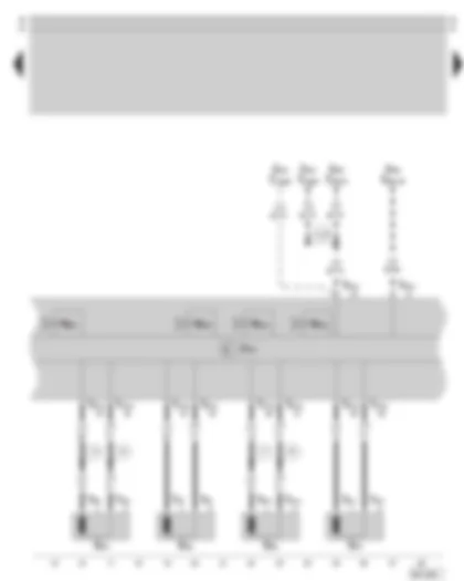
| F | Brake light switch |
| J104 | ABS control unit with EDL and TCS/ESP |
| J105 | ABS return flow pump relay |
| J106 | ABS solenoid valve relay |
| N133 | ABS inlet valve, rear right |
| N134 | ABS inlet valve, rear left |
| N135 | ABS outlet valve, rear right |
| N136 | ABS outlet valve, rear left |
| S162 | Fuse in fuse holder on the battery |
| S163 | Fuse in fuse holder on the battery |
| T3f | 3-pin connector, on the fuse holder on the battery |
| T4n | 4-pin connector, at brake pedal switch |
| T16a | 16-pin connector, in glove compartment on the driver's side (diagnostic connection) |
| T47a | 47-pin connector, at control unit for ESP |
| V64 | ABS hydraulic pump |
| 12 | Earth point, below the battery on the left |
| A18 | Connection (54), in wiring harness behind dash panel, left |
| A76 | Connection (diagnosis wire K), in wiring harness behind dash panel |
| P1 | Positive connection (30), in fuse holder on the battery |
| G44 | Rear right speed sensor |
| G45 | Front right speed sensor |
| G46 | Rear left speed sensor |
| G47 | Front left speed sensor |
| J104 | ABS control unit with EDL and TCS/ESP |
| J343 | Left gas discharge (xenon) lamp control unit |
| J503 | Navigation system control unit |
| N99 | ABS inlet valve, front right |
| N100 | ABS outlet valve, front right |
| N101 | ABS inlet valve, front left |
| N102 | ABS outlet valve, front left |
| T2k | 2-pin connector, at speed sensor, rear right |
| T2l | 2-pin connector, at speed sensor, front right |
| T2m | 2-pin connector, at speed sensor, rear left |
| T2n | 2-pin connector, at speed sensor, front left |
| T12g | 12-pin connector, at the gas discharge lamp, left |
| T26a | 26-pin connector, at navigation system control unit |
| T47a | 47-pin connector, at control unit for ESP |
| A133 | Connection (ABS, impulse left), in wiring harness behind dash panel |
| J3 | Connection, in wiring harness, rear right |
| J5 | Connection, in wiring harness, rear right |
| J7 | Connection, in wiring harness, rear left |
| J8 | Connection, in wiring harness, rear left |
| only for vehicles with navigation system and or with gas discharge lamps |
| only on vehicles with gas discharge lamps |
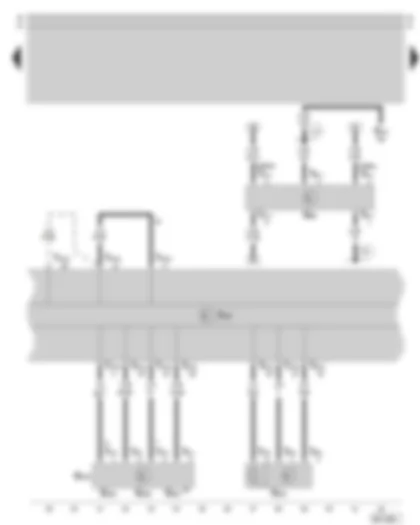
| G85 | Steering angle sender, on steering column |
| G200 | Lateral acceleration sender, next to steering column |
| G201 | Brake pressure sender -1-, at master brake cylinder |
| G202 | Yaw rate sender, next to steering column |
| G251 | Longitudinal acceleration sender, next to steering column |
| G419 | ESP sensor unit, next to steering column |
| J104 | ABS control unit with EDL and TCS/ESP |
| S15 | Fuse in fuse holder |
| T3o | 3-pin connector, at brake pressure sender -1-, at master brake cylinder |
| T4x | 4-pin connector, at the ESP sensor unit |
| T6w | 6-pin connector, at steering angle sender |
| T47a | 47-pin connector, at control unit for ESP |
| 81 | Earth connection, in wiring harness behind dash panel |
| U4 | Positive connection (30), in wiring harness behind dash panel |
| * | only for vehicles with four-wheel drive |
| not valid for vehicles with four-wheel drive |
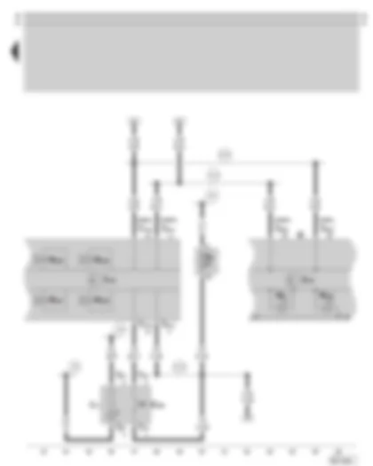
| E256 | TCS/ESP switch |
| J104 | ABS control unit with EDL and TCS/ESP |
| J218 | Combi-processor in dash panel insert |
| K | Dash panel insert |
| K47 | ABS warning lamp |
| K155 | ESP warning lamp |
| L71 | TCS/ESP switch illumination |
| N225 | Vehicle stabilising program switch valve -1- |
| N226 | Vehicle stabilising program switch valve -2- |
| N227 | Vehicle stabilising program high pressure valve -1- |
| N228 | Vehicle stabilising program high pressure valve -2- |
| T4f | 4-pin connector, at TCS/ESP button |
| T32b | 32-pin connector, at dash panel insert (green) |
| T47a | 47-pin connector, at control unit for ESP |
| 81 | Earth connection, in wiring harness behind dash panel |
| A2 | Positive connection (15), in wiring harness behind dash panel |
| A4 | Positive connection (58b), in wiring harness behind dash panel |
| A104 | Positive connection (15a), in wiring harness behind dash panel, left |
| A121 | Connection (H bus), in wiring harness behind dash panel, left |
| A122 | Connection (L bus), in wiring harness behind dash panel, left |


 Русский


