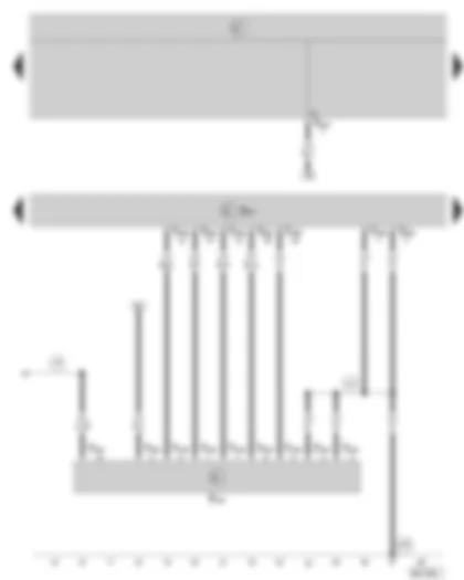
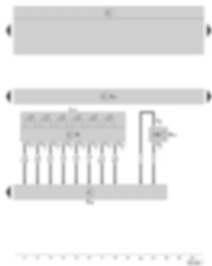
Wiring Diagram SKODA OCTAVIA II 2006 - Automatic gearbox control unit - fuse holder

| J217 | Automatic gearbox control unit, below the front left mud wing |
| SC6 | Fuse -6-, in fuse holder |
| SC14 | Fuse -14-, in fuse holder |
| SC39 | Fuse -39-, in fuse holder |
| T52b | 52-pin connector, at automatic gearbox control unit |
| A20 | Positive connection -1- (15a), in dash panel wiring harness |
| B278 | Positive connection -2- (15a), in interior wiring harness |
| B318 | Positive connection -4- (30a), in interior wiring harness |
| U8 | Positive connection (15a), in automatic gearbox wiring harness |
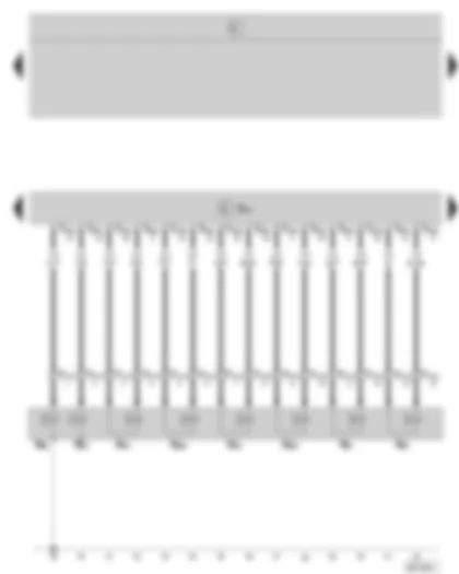
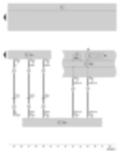
Wiring Diagram SKODA OCTAVIA II 2006 - Automatic gearbox control unit - Multi-function switch
| F125 | Multi-function switch |
| J217 | Automatic gearbox control unit, below the front left mud wing |
| T10s | 10-pin connector, at multi-function switch |
| T16a | 16-pin connector, on the onboard power supply control unit (black) |
| T52b | 52-pin connector, at automatic gearbox control unit |
| 114 | Earth connection, in automatic gearbox wiring harness |
| 672 | Earth point -2-, on left in engine compartment (at longitudinal member) |
| U8 | Positive connection (15a), in automatic gearbox wiring harness |
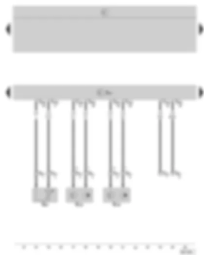
Wiring Diagram SKODA OCTAVIA II 2006 - Automatic gearbox control unit - Solenoid valves
| J217 | Automatic gearbox control unit, below the front left mud wing |
| N88 | Solenoid valve -1- |
| N89 | Solenoid valve -2- |
| N90 | Solenoid valve -3- |
| N91 | Solenoid valve -4- |
| N92 | Solenoid valve -5- |
| N93 | Solenoid valve -6- |
| N282 | Solenoid valve -9- |
| N283 | Solenoid valve -10- |
| T14c | 14-pin connector, on automatic Gearbox |
| T52b | 52-pin connector, at automatic gearbox control unit |
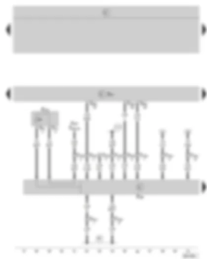
Wiring Diagram SKODA OCTAVIA II 2006 - Automatic gearbox control unit - Gearbox oil temperature sender - Gearbox input speed sender - Gearbox output speed sender
| G93 | Gearbox oil temperature sender |
| G182 | Gearbox input speed sender |
| G195 | Gearbox output speed sender |
| J217 | Automatic gearbox control unit, below the front left mud wing |
| T8u | 8-pin connector, on automatic Gearbox |
| T52b | 52-pin connector, at automatic gearbox control unit |
Wiring Diagram SKODA OCTAVIA II 2006 - Automatic gearbox control unit - tiptronic switch - selector lever switch locked in position P
| F189 | Tiptronic switch |
| F319 | Selector lever locked in position P switch |
| J217 | Automatic gearbox control unit, below the front left mud wing |
| J527 | Steering column electronics control unit |
| T4c | 4-pin connector, at selector lever |
| T10p | 10-pin connector, at Tiptronic switch |
| T20a | 20-pin connector, at steering column electronics control unit |
| T52b | 52-pin connector, at automatic gearbox control unit |
| 381 | Earth connection -16-, in interior wiring harness |
| A116 | Connection -2- (58d), in dash panel wiring harness |
Wiring Diagram SKODA OCTAVIA II 2006 - Automatic gearbox control unit - tiptronic switch - selector lever position magnet - selector lever position indicator
| F189 | Tiptronic switch |
| J217 | Automatic gearbox control unit, below the front left mud wing |
| L101 | Bulb for selector lever display illumination |
| N110 | Selector lever lock magnet |
| T4c | 4-pin connector, at selector lever |
| T10t | 10-pin connector, on the selector lever position indicator |
| Y6 | Selector lever position indicator |
Wiring Diagram SKODA OCTAVIA II 2006 - Automatic gearbox control unit - data bus diagnostic interface - dash panel insert
| J217 | Automatic gearbox control unit, below the front left mud wing |
| J285 | Control unit in dash panel insert |
| J533 | Data bus diagnostic interface, below dash panel, centre |
| K | Dash panel insert |
| K169 | Selector lever lock warning lamp |
| T16b | 16-pin connector, for diagnostic connection, below dash panel, left |
| T20c | 20-pin connector, at data bus diagnostic interface |
| T36a | 36-pin connector, at dash panel insert |
| T52b | 52-pin connector, at automatic gearbox control unit |
| Y6 | Selector lever position indicator |
| A76 | Connection (diagnosis wire K), in dash panel wiring harness |
| B383 | Connection -1- (CAN H, drive), in interior wiring harness |
| B390 | Connection -1- (CAN L, drive), in interior wiring harness |
Can't find your car? Check -> DiagnostData.com!

