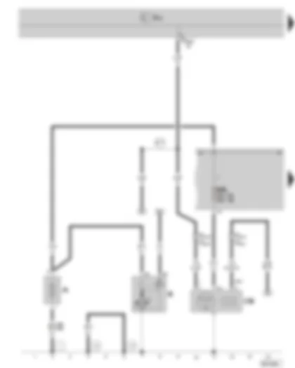
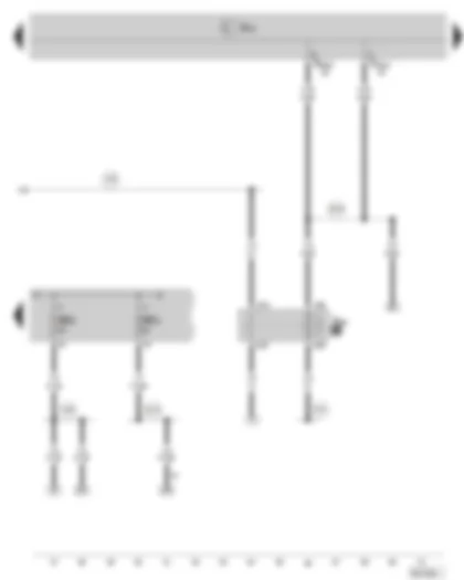
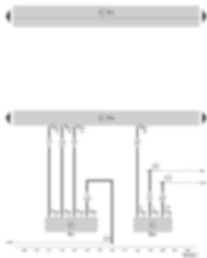
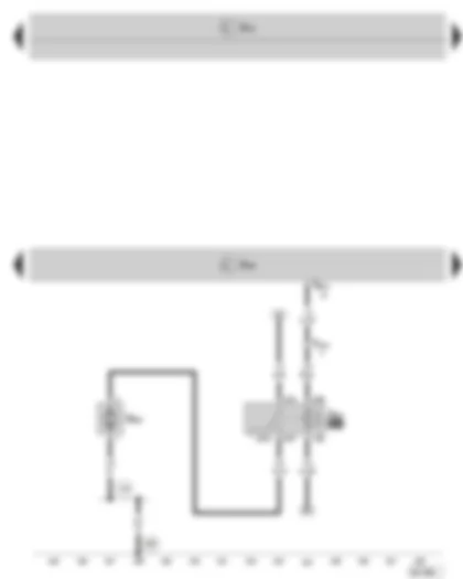
| A | Battery |
| B | Starter |
| CX1 | Alternator with voltage regulator |
| J519 | Onboard power supply control unit |
| SA1 | Fuse -1- (30), in the E box |
| T2t | 2-pin connector, in engine compartment, front left (on vehicles with heating) |
| T4n | 4-pin connector, in engine compartment, front left (on vehicles with Climatic / Climatronic) |
| T52ac | 52-pin connector, on the onboard power supply control unit (brown) |
| 1 | Earth strap, battery body |
| 12 | Earth point, on left in engine compartment (at longitudinal member) |
| 14 | Earth point, on gearbox |
| B177 | Connection (61), in interior wiring harness |
| *1 | on vehicles with alternator 90A / 110A |
| *2 | on vehicles with alternator 140A |
| *3 | not valid for vehicles with automatic gearbox |
| *4 | for vehicles with automatic gearbox |
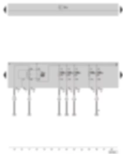
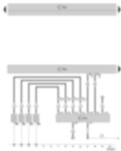
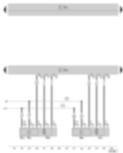
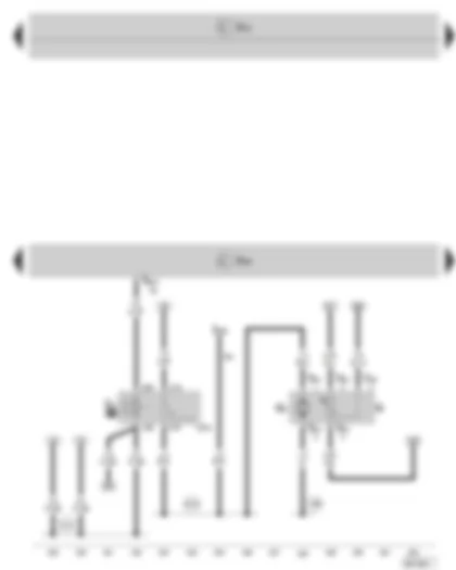
| J293 | Radiator fan control unit |
| J519 | Onboard power supply control unit |
| SB10 | Fuse -10-, in the E box |
| SB20 | Fuse -20-, in the E box |
| SB23 | Fuse -23-, in the E box |
| SB24 | Fuse -24-, in the E box |
| SB27 | Fuse -27-, in the E box |
| T4p | 4-pin connector, in the holder on the left radiator |
| T40a | 40-pin connector, at the E box |
| TV23 | Push-in bridge, in the E box |
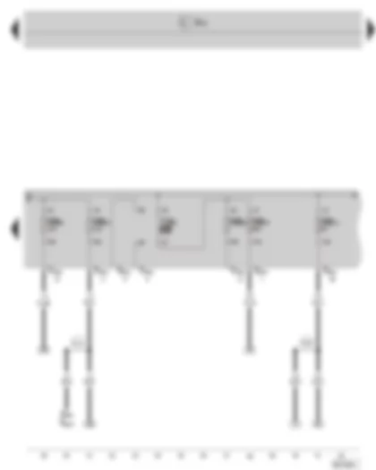
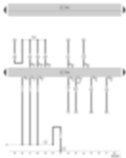
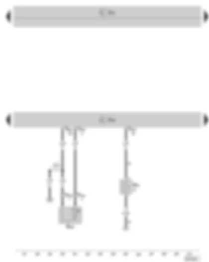
| D78 | Positive connection -1- (30a), in engine compartment wiring harness |
| D101 | Connection (87a), in engine compartment wiring harness |
| J519 | Onboard power supply control unit |
| J749 | Fuel pump relay for additional heater, at additional relay holder above the onboard power supply control unit |
| SC1 | Fuse -1-, in fuse holder |
| SC27 | Fuse -27-, in fuse holder |
| SC29 | Fuse -29-, in fuse holder |
| SC30 | Fuse -30-, in fuse holder |
| SC31 | Fuse -31-, in fuse holder |
| A20 | Positive connection -1- (15a), in dash panel wiring harness |
| B280 | Positive connection -4- (15a), in interior wiring harness |
| B315 | Positive connection -1- (30a), in interior wiring harness |
| B323 | Positive connection -9- (30a), in interior wiring harness |
| * | only on vehicles with optional equipment |
| ** | on vehicles with auxiliary heating |
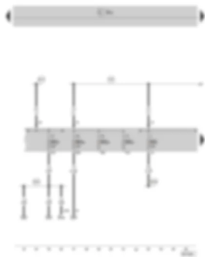
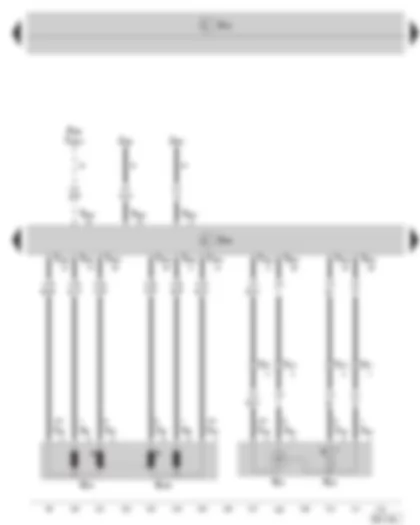
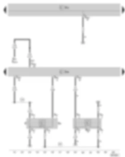
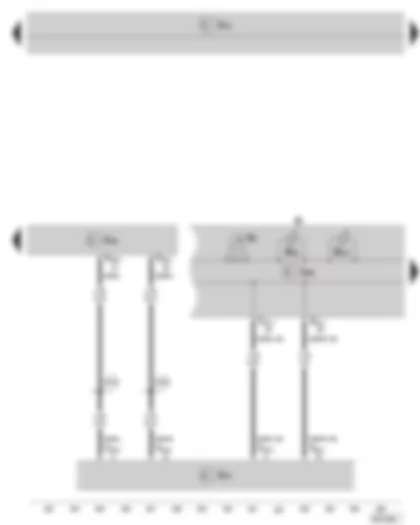
| J519 | Onboard power supply control unit |
| J682 | Terminal 50 voltage supply relay, at relay holder below the onboard power supply control unit |
| SC2 | Fuse -2-, in fuse holder |
| SC4 | Fuse -4-, in fuse holder |
| T52ab | 52-pin connector, on the onboard power supply control unit (white) |
| T52ac | 52-pin connector, on the onboard power supply control unit (brown) |
| 374 | Earth connection -9-, in interior wiring harness |
| A20 | Positive connection -1- (15a), in dash panel wiring harness |
| A38 | Positive connection -2- (15a), in dash panel wiring harness |
| B239 | Positive connection -1- (50), in interior wiring harness |
| B279 | Positive connection -3- (15a), in interior wiring harness |
| * | only on vehicles with extended servicing intervals (ESI) |
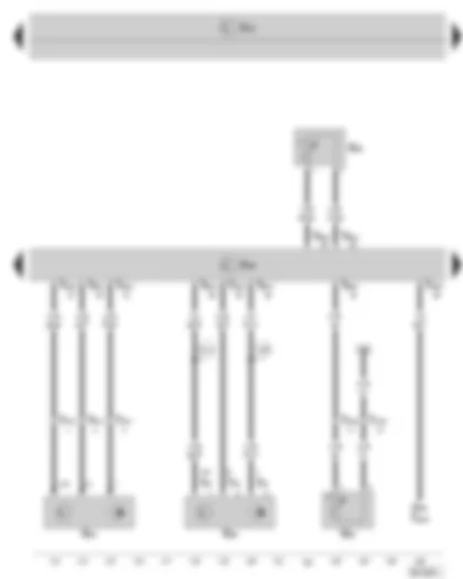
| F268 | Additional heating heater element contact switch (PTC) |
| G31 | Charge air pressure sender |
| G42 | Intake air temperature sender |
| G79 | Accelerator pedal position sender |
| G185 | Accelerator pedal position sender -2- |
| J248 | Diesel direct injection system control unit |
| J359 | Low heat output relay, at additional relay holder above the onboard power supply control unit |
| J360 | High heat output relay, at additional relay holder above the onboard power supply control unit |
| J519 | Onboard power supply control unit |
| T4f | 4-pin connector, in the holder on the gearbox (black) |
| T4o | 4-pin connector, at charge air pressure sender and intake air temperature sender |
| T6l | 6-pin connector, at accelerator pedal position sender |
| T20b | 20-pin connector, on the heating and fresh air control |
| T94a | 94-pin connector, at engine control unit |
| * | only on vehicles with additional heater (PTC) |
| only on vehicles with heating |
| G28 | Engine speed sender |
| G40 | Camshaft position sender |
| G62 | Coolant temperature sender |
| G83 | Coolant temperature sender at radiator outlet |
| J248 | Diesel direct injection system control unit |
| J293 | Radiator fan control unit |
| J519 | Onboard power supply control unit |
| T3l | 3-pin connector, at engine speed sender |
| T3m | 3-pin connector, at camshaft position sender |
| T4p | 4-pin connector, in the holder on the left radiator |
| T14a | 14-pin connector, on front left in engine compartment (black) |
| T60a | 60-pin connector, at engine control unit |
| T94a | 94-pin connector, at engine control unit |
| 220 | Earth connection (sender earth), in engine wiring harness |
| D141 | Connection (5V), in engine wiring harness |
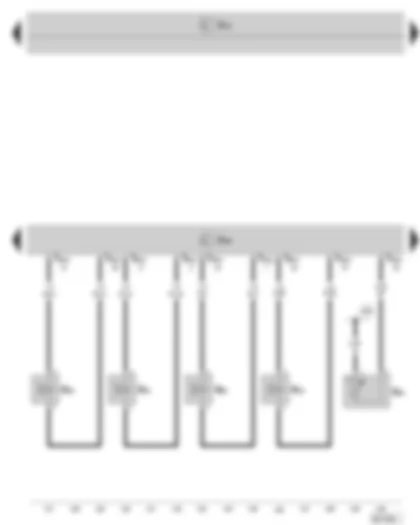
| G247 | Fuel pressure sender |
| J248 | Diesel direct injection system control unit |
| J519 | Onboard power supply control unit |
| N345 | Exhaust gas recirculation cooler change-over valve |
| T3z | 3-pin connector, at fuel pressure sender |
| T3aa | 3-pin connector, at the coolant circulation pump 2 |
| T14a | 14-pin connector, on front left in engine compartment (black) |
| T60a | 60-pin connector, at engine control unit |
| T94a | 94-pin connector, at engine control unit |
| V178 | Coolant circulation pump 2 |
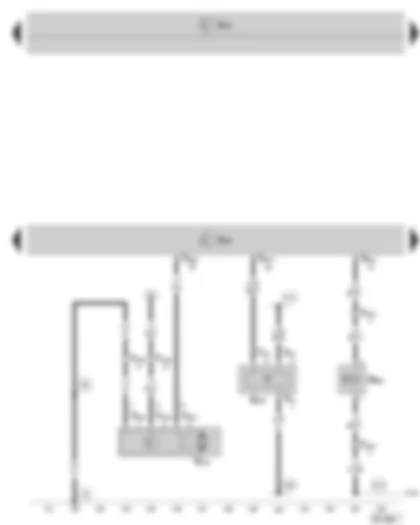
| 44 | Earth point -1-, on lower part of left A-pillar |
| 85 | Earth connection -1-, in engine compartment wiring harness |
| 220 | Earth connection (sender earth), in engine wiring harness |
| D102 | Connection (87a), in engine compartment wiring harness |
| D141 | Connection (5V), in engine wiring harness |
| J248 | Diesel direct injection system control unit |
| J519 | Onboard power supply control unit |
| N75 | Charge pressure control solenoid valve |
| N276 | Fuel pressure regulating valve |
| N290 | Fuel metering valve |
| T14a | 14-pin connector, on front left in engine compartment (black) |
| T60a | 60-pin connector, at engine control unit |
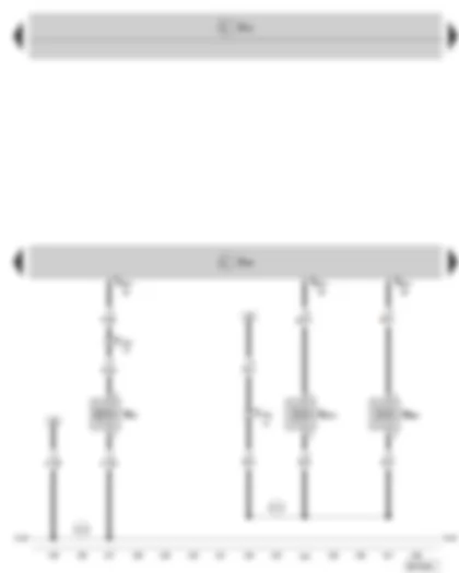
| D102 | Connection (87a), in engine compartment wiring harness |
| D173 | Connection (87a), in engine wiring harness |
| G70 | Air mass meter |
| G581 | Position sensor for charge air pressure actuator |
| J248 | Diesel direct injection system control unit |
| J519 | Onboard power supply control unit |
| T3g | 3-pin connector, at position sensor for charge air pressure actuator |
| T4ak | 4-pin connector, at air mass meter |
| T60a | 60-pin connector, at engine control unit |
| T94a | 94-pin connector, at engine control unit |
| 220 | Earth connection (sender earth), in engine wiring harness |
| D102 | Connection (87a), in engine compartment wiring harness |
| D141 | Connection (5V), in engine wiring harness |
| G69 | Throttle valve potentiometer |
| G212 | Exhaust gas recirculation potentiometer |
| J248 | Diesel direct injection system control unit |
| J338 | Throttle valve control unit |
| J519 | Onboard power supply control unit |
| N18 | Exhaust gas recirculation valve |
| T5r | 5-pin connector, on the throttle valve control unit |
| T6x | 6-pin connector, on exhaust gas recirculation control motor |
| T60a | 60-pin connector, at engine control unit |
| V338 | Exhaust gas recirculation control motor |
| 220 | Earth connection (sender earth), in engine wiring harness |
| D141 | Connection (5V), in engine wiring harness |
| G235 | Exhaust gas temperature sender -1- |
| J248 | Diesel direct injection system control unit |
| J519 | Onboard power supply control unit |
| N79 | Heating resistor for crankcase ventilation |
| T2aa | 2-pin connector, at exhaust gas temperature sender -1- (black), at the front wall, left |
| T94a | 94-pin connector, at engine control unit |
| 327 | Earth connection (sender earth), in engine compartment wiring harness |
| * | only on vehicles with optional equipment |
| F | Brake light switch, at master brake cylinder |
| F47 | Brake pedal switch, at master brake cylinder |
| G476 | Clutch position sender |
| J248 | Diesel direct injection system control unit |
| J519 | Onboard power supply control unit |
| J527 | Steering column electronics control unit |
| T4c | 4-pin connector, at brake pedal switch |
| T5j | 5-pin connector, at clutch position sender |
| T16n | 16-pin connector, at steering column electronics control unit |
| T52ac | 52-pin connector, on the onboard power supply control unit (brown) |
| T94a | 94-pin connector, at engine control unit |
| 374 | Earth connection -9-, in interior wiring harness |
| A18 | Connection (54), in dash panel wiring harness |
| * | not valid for vehicles with automatic gearbox |
| J248 | Diesel direct injection system control unit |
| J519 | Onboard power supply control unit |
| J832 | Additional fuel pump relay, at additional relay holder above the onboard power supply control unit |
| T14a | 14-pin connector, on front left in engine compartment (black) |
| T60a | 60-pin connector, at engine control unit |
| V393 | Additional fuel pump |
| 124 | Earth connection, in engine compartment right wiring harness |
| 685 | Earth point -1-, at front right longitudinal member |
| G | Fuel gauge sender |
| G6 | Fuel pump |
| J17 | Fuel pump relay, at relay holder below the onboard power supply control unit |
| J248 | Diesel direct injection system control unit |
| J519 | Onboard power supply control unit |
| J749 | Fuel pump relay for additional heater, at additional relay holder above the onboard power supply control unit |
| T5k | 5-pin connector, on the fuel pump |
| T94a | 94-pin connector, at engine control unit |
| 366 | Earth connection -1-, in interior wiring harness |
| B429 | Connection (EKPR), in interior wiring harness |
| D181 | Connection -2- (87a), in engine compartment wiring harness |
| *1 | on vehicles with auxiliary heating |
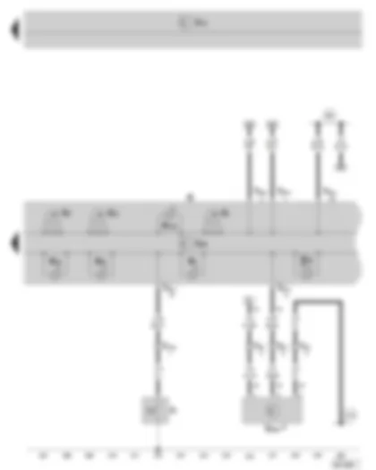
| G3 | Coolant temperature gauge |
| J248 | Diesel direct injection system control unit |
| J285 | Control unit in dash panel insert |
| J519 | Onboard power supply control unit |
| J533 | Data bus diagnostic interface, below dash panel |
| K | Dash panel insert |
| K28 | Coolant temperature and coolant shortage indicator warning lamp |
| K231 | Diesel particle filter warning light |
| T20c | 20-pin connector, at data bus diagnostic interface |
| T32c | 32-pin connector, at dash panel insert |
| T94a | 94-pin connector, at engine control unit |
| B383 | Connection -1- (CAN H, drive), in interior wiring harness |
| B390 | Connection -1- (CAN L, drive), in interior wiring harness |
| F1 | Oil pressure switch |
| G1 | Fuel gauge |
| G5 | Rev. Counter |
| G21 | Speedometer |
| G266 | Oil level/oil temperature sender |
| J285 | Control unit in dash panel insert |
| J519 | Onboard power supply control unit |
| K | Dash panel insert |
| K3 | Oil pressure warning lamp |
| K29 | Glow period warning lamp |
| K38 | Oil level warning lamp |
| K83 | Exhaust emissions warning lamp |
| K105 | Fuel reserve warning lamp |
| T6j | 6-pin connector, on front left in engine compartment (black) |
| T14a | 14-pin connector, on front left in engine compartment (black) |
| T32c | 32-pin connector, at dash panel insert |
| 269 | Earth connection (sender earth) -1-, in dash panel wiring harness |
| 374 | Earth connection -9-, in interior wiring harness |
| * | only on vehicles with extended servicing intervals (ESI) |
 Deutsch
 English
 English
 Español
 Français
 Nederlands
 Русский

