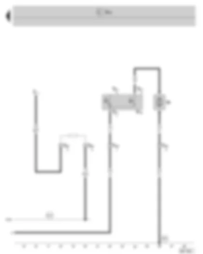
Wiring Diagram SKODA OCTAVIA II 2013 - E box
| A | Battery |
| J271 | Motronic current supply relay, in the E box |
| J322 | Diesel direct injection system relay, in the E box |
| J363 | Current supply relay for Simos, in the E box |
| J437 | Electric drive main relay, in the E box |
| J519 | Onboard power supply control unit |
| SA3 | Fuse -3- (30), in the E box |
| SB24 | Fuse -24-, in the E box |
| T40a | 40-pin connector, at the E box |
| D101 | Connection (87a), in engine compartment wiring harness |
| * | depending upon the engine identification characters |
Wiring Diagram SKODA OCTAVIA II 2013 - Radiator fan - radiator fan thermal switch
| F18 | Radiator fan thermal switch |
| J519 | Onboard power supply control unit |
| J... | Engine control units |
| T3y | 3-pin connector, on radiator fan thermal switch |
| T4p | 4-pin connector, in the holder on the left radiator |
| V7 | Radiator fan |
| 673 | Earth point -3-, on left in engine compartment (at longitudinal member) |
| D101 | Connection (87a), in engine compartment wiring harness |
 Deutsch
 English
 English
 Español
 Français
 Nederlands
 Русский


