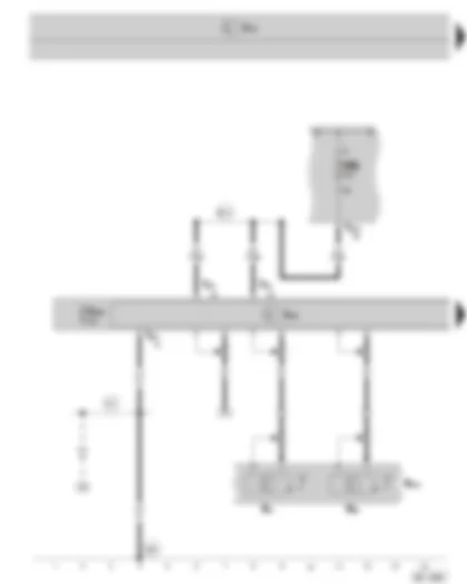
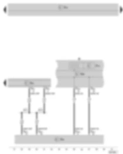
Wiring Diagram SKODA SUPERB II 2008 - Control unit with display for radio and navigation system - aerial - navigation system aerial - fuse holder B on the E box
| J503 | Control unit with display for radio and navigation system |
| J519 | Vehicle voltage control unit |
| R11 | Aerial |
| R50 | Navigation system aerial |
| R216 | Roof aerial |
| S258 | Navigation system fuse |
| SB8 | Fuse 8 on fuse holder B |
| T8o | 8-pin connector, on control unit with display for radio and navigation system (black) |
| T40a | 40-pin connector, at the E box |
| 477 | Earth connection (audio), in main wiring harness |
| 687 | Earth point 1 on the middle tunnel |
| B614 | Positive connection 23 (30a) in main wiring harness |
| for vehicles with CD changer |
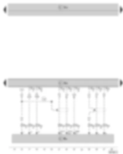
Wiring Diagram SKODA SUPERB II 2008 - Control unit with display for radio and navigation system - CD changer
| J503 | Control unit with display for radio and navigation system |
| J519 | Vehicle voltage control unit |
| R41 | CD changer |
| T12j | 12-pin connector, at CD changer |
| T12l | 12-pin connector, on control unit with display for radio and navigation system (blue) |
| V14 | Connection (screening), in CD changer wiring harness |
| for vehicles with CD changer |
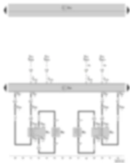
Wiring Diagram SKODA SUPERB II 2008 - Control unit with display for radio and navigation system - Front loudspeaker
| J412 | Mobile telephone operating electronics control unit |
| J503 | Control unit with display for radio and navigation system |
| J519 | Vehicle voltage control unit |
| R20 | Treble loudspeaker, front left |
| R21 | Bass loudspeaker, front left |
| R22 | Treble loudspeaker, front right |
| R23 | Bass loudspeaker, front right |
| T4ba | 4-pin connector, at bass loudspeaker, front left |
| T4bb | 4-pin connector, at bass loudspeaker, front right |
| T8p | 8-pin connector, on control unit with display for radio and navigation system (brown) |
| T12o | 12-pin connector, on control unit with display for radio and navigation system (green) |
| T28a | 28-pin connector, on the left A-pillar |
| T28b | 28-pin connector, on the right A-pillar |
| T54b | 54-pin connector, at mobile telephone operating electronics control unit |
| *1 | for vehicles with telephone bracket |
| for vehicles with telephone preinstallation 2 |
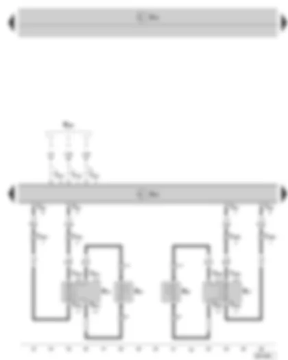
Wiring Diagram SKODA SUPERB II 2008 - Control unit with display for radio and navigation system - Rear loudspeaker
| J503 | Control unit with display for radio and navigation system |
| J519 | Vehicle voltage control unit |
| R14 | Treble loudspeaker, rear left |
| R15 | Bass loudspeaker, rear left |
| R16 | Treble loudspeaker, rear right |
| R17 | Bass loudspeaker, rear right |
| R199 | Connection for external audio sources |
| T4bc | 4-pin connector, at bass loudspeaker, rear left |
| T4bd | 4-pin connector, at bass loudspeaker, rear right |
| T8p | 8-pin connector, on control unit with display for radio and navigation system (brown) |
| T12l | 12-pin connector, on control unit with display for radio and navigation system (blue) |
| T28c | 28-pin connector, on the left B-pillar |
| T28d | 28-pin connector, on the right B-pillar |
| for vehicles with connection for external audio sources |
Wiring Diagram SKODA SUPERB II 2008 - Control unit with display for radio and navigation system - data bus diagnostic interface - dash panel insert
| J119 | Multi-function display |
| J285 | Control unit in dash panel insert |
| J503 | Control unit with display for radio and navigation system |
| J519 | Vehicle voltage control unit |
| J533 | Data bus diagnostic interface |
| K | Dash panel insert |
| T8o | 8-pin connector, on control unit with display for radio and navigation system (black) |
| T20c | 20-pin connector, at data bus diagnostic interface |
| T32a | 32-pin connector, at dash panel insert |
| B415 | Connection 1 (Infotainment CAN bus, High) in main wiring harness |
| B421 | Connection 1 (Infotainment CAN bus, Low) in main wiring harness |
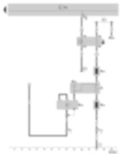
Wiring Diagram SKODA SUPERB II 2008 - Rear window aerial 1 - right aerial module - frequency filter for frequency modulation (FM) - heated rear window relay - heated rear window
| J9 | Heated rear window relay |
| J519 | Vehicle voltage control unit |
| R109 | Aerial module, right |
| R130 | Rear window aerial 1 |
| R178 | Frequency filter for frequency modulation (FM) in the negative line |
| R179 | Frequency filter for frequency modulation (FM) in the positive line |
| SC25 | Fuse 25 on fuse holder C |
| T2t | 2-pin connector in right luggage compartment (beige) |
| T11a | 11-pin connector, in luggage compartment, right |
| T52b | 52-pin connector, at onboard supply control unit (white) |
| Z1 | Heated rear window |
| 51 | Earth point in luggage compartment, right |
| B315 | Positive connection 1 (30a) in main wiring harness |
| B316 | Positive connection 2 (30a) in main wiring harness |
Didn't find a car made after 2014? Look here -> DiagnostData.com!

 Русский
