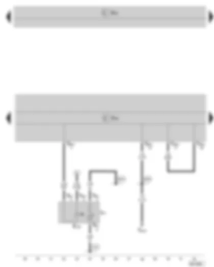
Wiring Diagram SKODA SUPERB II 2009 - ABS control unit - fuse holder B on the E box - fuse holder C in the dash panel


| E226 | Tyre pressure monitor button |
| J104 | ABS control unit |
| J519 | Vehicle voltage control unit |
| N99 | ABS inlet valve, front right |
| N100 | ABS outlet valve, front right |
| N101 | ABS inlet valve, front left |
| N102 | ABS outlet valve, front left |
| SB25 | Fuse 25 on fuse holder B |
| SC2 | Fuse 2 on fuse holder C |
| T26a | 26-pin connector, at ABS control unit |
| T40a | 40-pin connector, at the E box |
| V64 | ABS hydraulic pump |
| 43 | Earth point lower part of right A-pillar |
| B281 | Positive connection 5 (15a) in main wiring harness |
| B328 | Positive connection 14 (30a) in main wiring harness |
| *1 | for vehicles with tyre pressure monitor |
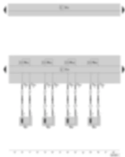
Wiring Diagram SKODA SUPERB II 2009 - ABS control unit - Speed sensor
| G44 | Rear right speed sensor |
| G45 | Front right speed sensor |
| G46 | Rear left speed sensor |
| G47 | Front left speed sensor |
| J104 | ABS control unit |
| J519 | Vehicle voltage control unit |
| N133 | ABS inlet valve, rear right |
| N134 | ABS inlet valve, rear left |
| N135 | ABS outlet valve, rear right |
| N136 | ABS outlet valve, rear left |
| T26a | 26-pin connector, at ABS control unit |
Wiring Diagram SKODA SUPERB II 2009 - ABS control unit - traction control system switch
| E132 | Traction control system switch |
| F | Brake light switch |
| J104 | ABS control unit |
| J519 | Vehicle voltage control unit |
| L71 | Bulb for lighting of traction control system switch |
| T4c | 4-pin connector, at brake pedal switch |
| T6u | 6-pin connector, at traction control system switch |
| T26a | 26-pin connector, at ABS control unit |
| 374 | Earth connection 9 in main wiring harness |
| B335 | Connection 1 (54) in main wiring harness |
| B340 | Connection 1 (58d) in main wiring harness |
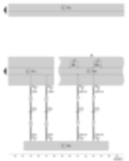
Wiring Diagram SKODA SUPERB II 2009 - ABS control unit - data bus diagnostic interface - dash panel insert
| J104 | ABS control unit |
| J285 | Control unit in dash panel insert |
| J519 | Vehicle voltage control unit |
| J533 | Data bus diagnostic interface |
| K | Dash panel insert |
| K47 | ABS warning light |
| K155 | ESP and TCS warning light |
| T20c | 20-pin connector, at data bus diagnostic interface |
| T26a | 26-pin connector, at ABS control unit |
| T32a | 32-pin connector, at dash panel insert |
| B383 | Connection 1 (drive train CAN bus High) in main wiring harness |
| B390 | Connection 1 (drive train CAN bus Low) in main wiring harness |
| B708 | Connection 1 (CAN bus dash panel insert High) in main wiring harness |
| B709 | Connection 1 (CAN bus dash panel insert Low) in main wiring harness |
Can't find your car? Check -> DiagnostData.com!


 Русский


