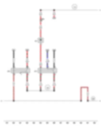
AUDI R8 2010 Fuses (SD) on main fuse box
In front right footwell -5- .
1 - Coupling station right behind centre console
2 - Centre loudspeaker -R148-
4 - onboard supply control unit -J519-
6 - Relay and fuse carrier in front right footwell
1 - Fuse 4 on fuse holder D -SD4-, 5 A, for onboard supply control unit -J519-
2 - Fuse 1 on fuse holder D -SD1-, 100 A, terminal 30 supply, fuse holder in relay and fuse carrier in front right footwell, up to May 2008
2 - Fuse 1 on fuse holder D -SD1-, 150 A, terminal 30 supply, fuse holder in relay and fuse carrier in front right footwell, from June 2008
3 - Fuse 2 on fuse holder D -SD2-, 100 A, terminal 30 supply, fuse holder in relay and fuse carrier in front right footwell
4 - Fuse 3 on fuse holder D -SD3-, 60 A, for ABS control unit -J104-
6 -
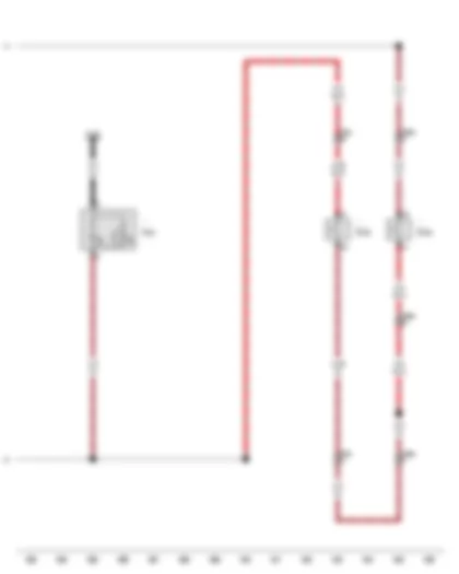
AUDI R8 2010 Fuses (S) on main distribution
In front right footwell -3- .
1 - Coupling station right behind centre console
2 - Centre loudspeaker -R148-
4 - onboard supply control unit -J519-
6 - Relay and fuse carrier in front right footwell
1 - Connection for wire from battery -A-
2 - Fuse 2 (30) -S205-, strip fuse 60 A, supply for fuse carrier ST3 on relay and fuse carrier in front right footwell
3 - Fuse 1 (30) -S204-, strip fuse 150 A, supply for fuse carrier ST3 on relay and fuse carrier in front right footwell
AUDI R8 2010 Position of fuses (SC) on fuse holder C
Behind rear panel, right -1- , Spyder.
1 - Fuse carrier ST1, black
2 - Fuse carrier ST2, red
3 - Fuse carrier ST3, black
q Position of fuses, V8 engine
q Position of fuses, V10 engine
No. Current Flow Diagram designation Nominal value Function/component Terminal 1 - Fuse 1 on fuse holder C -SC1- 10 A - Automatic gearbox control unit -J217- 15 2 - Fuse 2 on fuse holder C -SC2- 5 A - Engine control unit -J623- 15 3 - Fuse 3 on fuse holder C -SC3- 5 A - Oil level and oil temperature sender -G266- 15 4 - Fuse 4 on fuse holder C -SC4- 5 A - Electronically controlled damping control unit -J250- 15 5 - Vacant 6 - Vacant 7 - Fuse 7 on fuse holder C -SC7- 5 A - Engine control unit -J623- 30 8 - Fuse 8 on fuse holder C -SC8- 30 A - Gearbox hydraulic pump relay -J510- 30 9 - Fuse 9 on fuse holder C -SC9- 25 A - Automatic gearbox control unit -J217- 30 10 - Fuse 10 on fuse holder C -SC10- 30 A - Electronically controlled damping control unit -J250- 30 11 - Vacant 12 - Vacant
No. Current Flow Diagram designation Nominal value Function/component Terminal 1 - Fuse 1 on fuse holder C -SC1- 15 A - Lambda probe after catalytic converter -G130-1 1 87 2 - Fuse 2 on fuse holder C -SC2- 15 A - Lambda probe -G39-1 1 87 3 - Fuse 3 on fuse holder C -SC3- 15 A - Air mass meter -G70- 87 4 - Vacant 5 - Fuse 5 on fuse holder C -SC5- 15 A - Lambda probe after catalytic converter -G130-2 2 6 - Fuse 6 on fuse holder C -SC6- 15 A - Lambda probe -G39-2 2 7 - Fuse 7 on fuse holder C -SC7- 10 A - Camshaft control valve 1 -N205- 87 8 - Fuse 8 on fuse holder C -SC8- 30 A - Ignition coils -N....- 87 9 - Fuse 9 on fuse holder C -SC9- 15 A - Injectors -N....- 87 10 - Fuse 10 on fuse holder C -SC10- 5 A - Brake light switch -F- 87 11 - Fuse 11 on fuse holder C -SC11- 5 A - Radiator fan -V7- 87 12 - Vacant
No. Current Flow Diagram designation Nominal value Function/component Terminal 1 - Vacant 2 - Vacant 3 - Fuse 3 on fuse holder C -SC3- 15 A - Intake air temperature sender -G42- 87 4 - Vacant 5 - Fuse 5 on fuse holder C -SC5- 15 A - Lambda probe 1 heater after catalytic converter -Z29- 87 6 - Fuse 6 on fuse holder C -SC6- 15 A - Lambda probe heater -Z19- 87 7 - Fuse 7 on fuse holder C -SC7- 10 A - Camshaft control valve 1 -N205- 87 8 - Fuse 8 on fuse holder C -SC8- 30 A - Ignition coils -N....- 87 9 - Fuse 9 on fuse holder C -SC9- 15 A - Injectors -N....- 87 10 - Fuse 10 on fuse holder C -SC10- 5 A - Brake light switch -F- 87 11 - Fuse 11 on fuse holder C -SC11- 5 A - Radiator fan -V7- 87 12 - Vacant
1 - Fuse carrier ST1, black
2 - Fuse carrier ST2, black
3 - Fuse carrier ST3, black
q Position of fuses, V8 engine
q Position of fuses, V10 engine
No. Current Flow Diagram designation Nominal value Function/component Terminal 1 - Fuse 1 on fuse holder C -SC1- 10 A - Automatic gearbox control unit -J217- 15 2 - Fuse 2 on fuse holder C -SC2- 5 A - Engine control unit -J623- 15 3 - Fuse 3 on fuse holder C -SC3- 5 A - Oil level and oil temperature sender -G266- 15 4 - Fuse 4 on fuse holder C -SC4- 5 A - Electronically controlled damping control unit -J250- 15 5 - Vacant 6 - Vacant 7 - Fuse 7 on fuse holder C -SC7- 5 A - Engine control unit -J623- 30 8 - Fuse 8 on fuse holder C -SC8- 30 A - Gearbox hydraulic pump relay -J510- 30 9 - Fuse 9 on fuse holder C -SC9- 25 A - Automatic gearbox control unit -J217- 30 10 - Fuse 10 on fuse holder C -SC10- 30 A - Electronically controlled damping control unit -J250- 30 11 - Vacant 12 - Vacant
No. Current Flow Diagram designation Nominal value Function/component Terminal 1 - Fuse 1 on fuse holder C -SC1- 40 A - Convertible roof actuation hydraulic pump relay -J321- 30 2 - Fuse 2 on fuse holder C -SC2- 30 A - Convertible roof actuation control unit -J256- 30 3 - Fuse 3 on fuse holder C -SC3- 30 A - Rear window motor -V456- 30 4 - Vacant 5 - Vacant 6 - Fuse 6 on fuse holder C -SC6- 10 A - Convertible roof actuation control unit -J256- 30 7 - Vacant 8 - Vacant 9 - Vacant 10 - Vacant 11 - Vacant 12 - Vacant
No. Current Flow Diagram designation Nominal value Function/component Terminal 1 - Fuse 1 on fuse holder C -SC1- 15 A - Lambda probe after catalytic converter -G130-1 1 87 2 - Fuse 2 on fuse holder C -SC2- 15 A - Lambda probe -G39-1 1 87 3 - Fuse 3 on fuse holder C -SC3- 15 A - Air mass meter -G70- 87 4 - Vacant 5 - Fuse 5 on fuse holder C -SC5- 15 A - Lambda probe after catalytic converter -G130-2 2 87 6 - Fuse 6 on fuse holder C -SC6- 15 A - Lambda probe -G39-2 2 87 7 - Fuse 7 on fuse holder C -SC7- 10 A - Camshaft control valve 1 -N205- 87 8 - Fuse 8 on fuse holder C -SC8- 30 A - Ignition coils -N....- 87 9 - Fuse 9 on fuse holder C -SC9- 15 A - Injectors -N....- 87 10 - Fuse 10 on fuse holder C -SC10- 5 A - Brake light switch -F- 87 11 - Fuse 11 on fuse holder C -SC11- 5 A - Radiator fan -V7- 87 12 - Vacant
No. Current Flow Diagram designation Nominal value Function/component Terminal 1 - Vacant 2 - Vacant 3 - Fuse 3 on fuse holder C -SC3- 15 A - Intake air temperature sender -G42- 87 4 - Vacant 5 - Fuse 5 on fuse holder C -SC5- 15 A - Lambda probe 1 heater after catalytic converter -Z29- 87 6 - Fuse 6 on fuse holder C -SC6- 15 A - Lambda probe heater -Z19- 87 7 - Fuse 7 on fuse holder C -SC7- 10 A - Camshaft control valve 1 -N205- 87 8 - Fuse 8 on fuse holder C -SC8- 30 A - Ignition coils -N....- 87 9 - Fuse 9 on fuse holder C -SC9- 15 A - Injectors -N....- 87 10 - Fuse 10 on fuse holder C -SC10- 5 A - Brake light switch -F- 87 11 - Fuse 11 on fuse holder C -SC11- 5 A - Radiator fan -V7- 87 12 - Vacant
AUDI R8 2010 Fuses on 9 point relay and fuse carrier
Under right rear shelf -7- , Coupé.
Behind rear panel, right -2- , Spyder.
A - Secondary air pump fuse -S130-, 50 A
B - Fuel pump fuse -S81-, 40 A
D - Secondary air pump fuse 2 -S284-, 50 A
E - Convertible roof actuation fuse -S67-, 80 A, Spyder
AUDI R8 2010 Overview of earth points in rear part of vehicle
611 Earth connection, on fuel tank filler neck
q Earth cable gearbox-body
708 Earth point 2 on rear right longitudinal member -arrow-
On rear right longitudinal member.
611 Earth connection on filler neck, single pin connector -T1---Arrow--
On filler neck of fuel tank system.
714 Earth point on right of engine -arrow-
66 Earth point on rear right longitudinal member -arrow-
On rear right longitudinal member.
619 Earth point, on lower left of engine block -arrow-
710 Earth point 2 on rear left longitudinal member -arrow-
On rear left longitudinal member.
65 Earth point on rear left longitudinal member -arrow-
On rear left longitudinal member.
618 Earth point on left of engine -arrow-
711 Earth point 3 on rear left longitudinal member -arrow-
On rear left longitudinal member.
AUDI R8 2010 Overview of earth points in vehicle interior
637 Earth point, airbag control unit -arrow-
Near airbag control unit -J234-.
638 Earth point, right A-pillar -arrow-
on lower section of right A-pillar.
610 Earth point (audio) at front under centre console -arrow-
under front centre console.
689 Earth point at front centre of roof -arrow-
713 Earth point below and to back right of rear shelf -arrow-
Below and to back right of rear shelf.
718 Earth point (audio) below and to back of rear shelf -arrow-
Below and to back of rear shelf.
639 Earth point, left A-pillar -arrow-
on lower section of left A-pillar.
712 Earth point below and to back left of rear shelf -arrow-
Below and to back left of rear shelf.
42 Earth point next to steering column -arrow-
AUDI R8 2010 Overview of earth points in front part of vehicle
672 Earth point 2 at front of left longitudinal member -arrow-
at bottom on front of left longitudinal member
671 Earth point 1 at front of left longitudinal member -arrow-
on front of left longitudinal member.
715 Earth point on left of cross member -arrow-
717 Earth point on front right of cross member -arrow-
On front right of cross member.
716 Earth point on right of cross member -arrow-
On front right of cross member.
685 Earth point 1 on front of right longitudinal member -arrow-
At bottom on front of right longitudinal member.
AUDI R8 2010 Routing door
driver side interior locking button -E308-/front passenger side interior locking button -E309-
Front left mid-range loudspeaker -R103-/front right mid-range loudspeaker -R104- in the doors, centre
Side airbag crash sensor on driver side -G179-/side airbag crash sensor on front passenger side -G180-
Alarm system off switch -E217-/interior monitoring switch -E183-
Driver side central locking lock unit -F220-/Rear left central locking lock unit -F222-
8 - Driver door control unit -J386-/front passenger side door control unit -J387-
9 - Driver door control unit -J386-/front passenger side door control unit -J387-
Front left bass loudspeaker -R21-/front right bass loudspeaker -R23- in the doors, bottom
11 - Cable from door connection to door control units
AUDI R8 2010 Routing in the interior
19 - Door connection point
20 - Wiring harness to left A-pillar
21 - Data bus diagnostic interface -J533-
22 - Wiring harness to luggage compartment front left
23 - Steering column connections
24 - Wiring harness in direction of left dash panel
26 - Centre mid-range loudspeaker -R158-
27 - Navigation system with CD drive control unit -J401-
28 - Dash panel right wiring harness
AUDI R8 2010 Engine compartment routing
2 - Engine control unit -J623-
3 - Starter cable of vehicle floor
4 - Wiring harness engine compartment to engine prewiring
5 - Wiring harness engine compartment right to tail light
13 - Aerial amplifier -R24-
AUDI R8 2010 Roof/A-pillars routing
3 - Aerial amplifier 3 -R112-
6 - Aerial amplifier 2 -R111-
AUDI R8 2010 Routing luggage compartment
1 - Wire on front of right longitudinal member
2 - Connection on right headlight
4 - Cable from battery positive to main distribution in right front footwell
6 - Wire heated washer jets
7 - Windscreen wiper connection
8 - Cable from interior to front left longitudinal members
9 - Connector for ABS control unit -J104-
11 - Connection on left headlight
12 - Wire on front of left longitudinal member
13 - Wire on front cross member
14 - Garage door operation control unit -J530-
15 - Cable to condenser refrigerant circuit left
16 - Battery positive connection
17 - Air-conditioning connection
AUDI R8 2010 Dash panel routing
1 - Centre loudspeaker -R148-
2 - Wiring harness behind glove compartment
3 - Main distribution in right front footwell
4 - Right door connection
5 - Main fuse box, in front right footwell
6 - Wiring harness in right footwell
7 - Grommet, transition luggage compartment
8 - Relay and fuse carrier in front right footwell
9 - Radio -R-/navigation system with CD drive control unit -J401-
10 - Airbag control unit -J234-
11 - Grommet, transition luggage compartment
12 - Wiring harness in left footwell
14 - Data bus diagnostic interface -J533-
15 - Wiring harness along left module carrier
16 - Wiring harness to centre console
19 - Wiring harness along centre right module carrier
AUDI R8 2010 Overview of relay carriers
q Location and position of relays from June 2009
3 -
q Location and position of relays
AUDI R8 2010 Relay carrier, in front right footwell
2 - Relay for power sockets -J807-
3 - Brake servo relay -J569-
4 - Headlight washer system relay -J39-
4 - Glass partition heater relay -J884-
5 - Headlight washer system relay -J39-
6 - Continued coolant circulation relay -J151-
q only for super hot countries 8Z9
8 - Rear lid central locking relay -J380-
2 - Rear lid central locking relay -J380-
3 - Relay for power sockets -J807-
4 - Brake servo relay -J569-/additional coolant pump relay -J496-
5 - Terminal 15 voltage supply relay -J329-
7 - Headlight washer system relay -J39-
8 - Continued coolant circulation relay -J151-
10 - Heated rear window relay -J9-
1 - Terminal 15 voltage supply relay 2 -J681-
3 - Heated rear window relay -J9-
6 - Washer pump relay -J576-
9 - Terminal 30 voltage supply relay 2 -J689-
AUDI R8 2010 Relays on 9 point relay and fuse carrier
Under rear shelf on right -7- , Coupé
Behind rear panel on right -2- , Spyder
1 - Motronic current supply relay -J271-
2.1 - Terminal 15 relay -J940-
q only Audi R8 GT with Race Package
3 - Starter motor relay -J53-
4 - Starter motor relay 2 -J695-
5 - Secondary air pump relay -J299-
6 - Engine component current supply relay -J757-
7 - Gearbox hydraulic pump relay -J510-
8 - Secondary air pump 2 relay -J545-
9.1 - Relay for emergency off -J970-
q only Audi R8 GT with Race Package
9.2 - Motronic current supply relay 2 -J670-
q only Audi R8 GT with Race Package
AUDI R8 2010 Overview of coupling stations and connectors
q Connectors-T17-, -T17a-, -T17b-, -T17c-
q Connectors-T10f-, -T6e-, -T10d-, -T3e-
q Connectors-T17d-, -T17e-, -T17f-, -T17g-
q Connectors-T10e-, -T6d-, -T10c-, -T3d-
Left A-pillar coupling point
q Connectors-T17k-, -T17l-
AUDI R8 2010 Coupling station under right front seat
1 - 10-pin connector -T10f-, black
2 - 6-pin, connector -T6e-, green
3 - 10-pin connector -T10d-, red
4 - 3-pin connector -T3e-, yellow
AUDI R8 2010 Coupling stations under right rear shelf
Under right rear shelf -3- , Coupé.
Behind rear panel on right -3- , Spyder
1 - 17-pin connector -T17d-, brown
2 - 17-pin connector -T17e-, red
3 - 17-pin connector -T17f-, white
4 - 17-pin connector -T17g-, black
AUDI R8 2010 Coupling station under left front seat
1 - 10-pin connector -T10e-, black
2 - 6-pin, connector -T6d-, green
3 - 10-pin connector -T10c-, red
4 - 3-pin connector -T3d-, yellow
AUDI R8 2010 Coupling station right behind centre console
Behind glove compartment on left -arrow- .
3 - 17-pin connector -T17-, red
4 - 17-pin connector -T17a-, black
5 - 17-pin connector -T17b-, brown
6 - 17-pin connector -T17c-, blue
AUDI R8 2010 Diagnostic connection
Behind shelf on driver side.
A - 16-pin connector -T16-
AUDI R8 2010 Left A-pillar coupling point
Behind left A-pillar trim.
A - 17-pin connector -T17k-
B - 17-pin connector -T17l-
AUDI R8 2010 Coupling point, glove compartment
Behind glove compartment at right.
A - 6-pin, connector -T6c-, black
AUDI R8 2010 Rear bumper coupling point
Behind bumper trim on rear left.
A - 14-pin connector -T14d-, black
AUDI R8 2010 Front bumper coupling point
Behind bumper trim on front left.
A - 14-pin connector -T14e-, black
Can't find your car? Check -> DiagnostData.com !


/ engine control unit 2 J624 (left)")
/ engine control unit 2 J624 (left)")


 on fuse holder B")
 on fuse holder B")
 on fuse holder B")
 on main fuse box")
 on main distribution")
 on fuse holder C")
 on fuse holder C")


