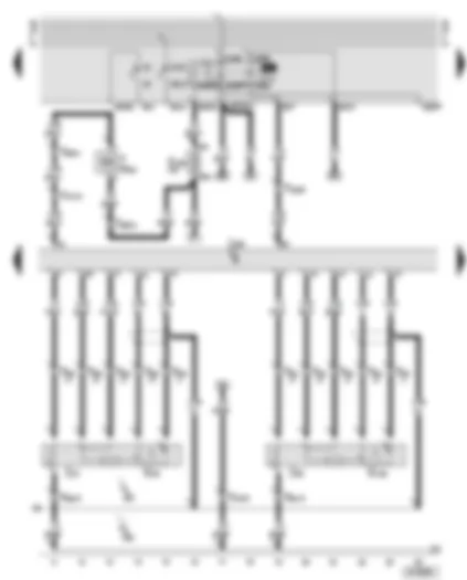
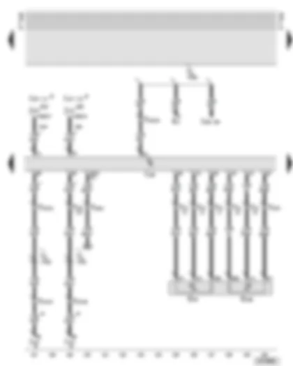
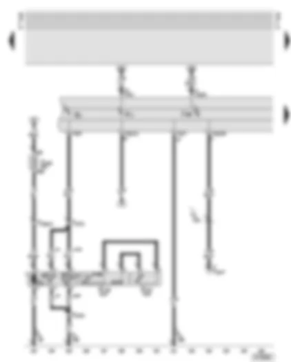
Wiring Diagram AUDI A6 2003 - Battery - starter - alternator - starter inhibitor relay

| A | Battery |
| B | Starter |
| C | Alternator |
| C1 | Voltage regulator |
| D | Ignition/starter switch |
| F125 | Multi-function switch |
| J207 | Starter inhibitor relay |
| S205 | Fuse -2- (30) |
| T1h | Single connector, black, in engine compartment, right |
| T2cl | 2-pin connector, black, on alternator |
| T9 | 9-pin connector, brown, at starter inhibitor relay |
| T10o | 10-pin connector, brown, connector point, electronics box, plenum chamber |
| T10p | 10-pin connector, black, connector point, electronics box, plenum chamber |
| T17m | 17-pin connector, blue, connector point, A pillar, right |
| 1 | Earth strap, battery - body |
| 44 | Earth point, lower part of left A pillar |
| 199 | Earth connection -3-, in dash panel wiring harness |
| A17 | Connection (61), in dash panel wiring harness |
| A41 | Positive (+) connection (50), in dash panel wiring harness |
| * | Models with manual gearbox |
| ** | Models with automatic gearbox 01V |
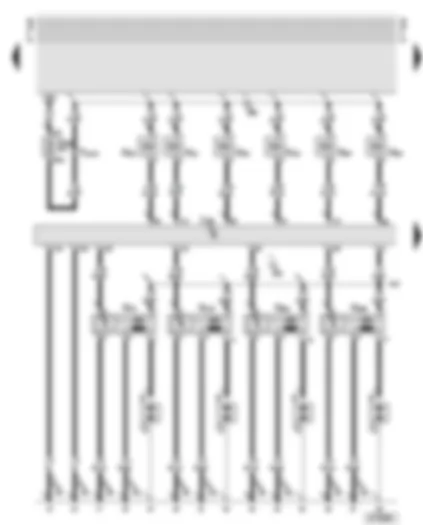
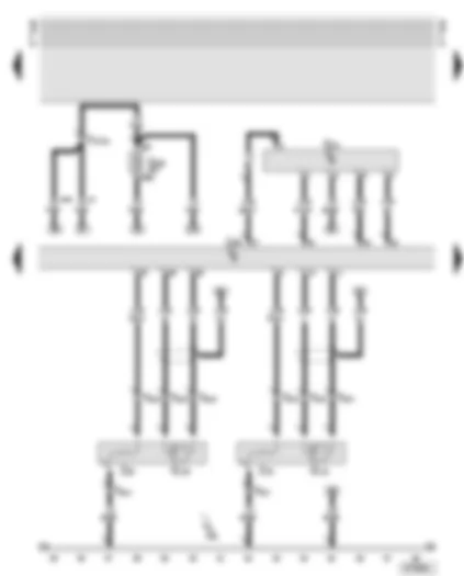
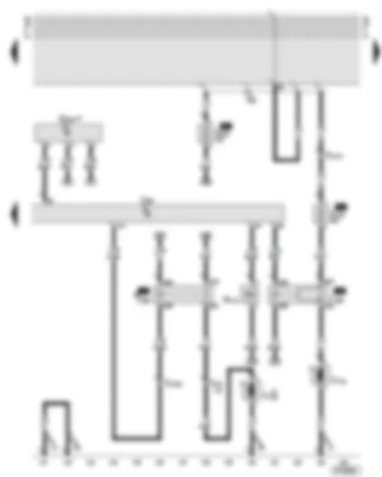
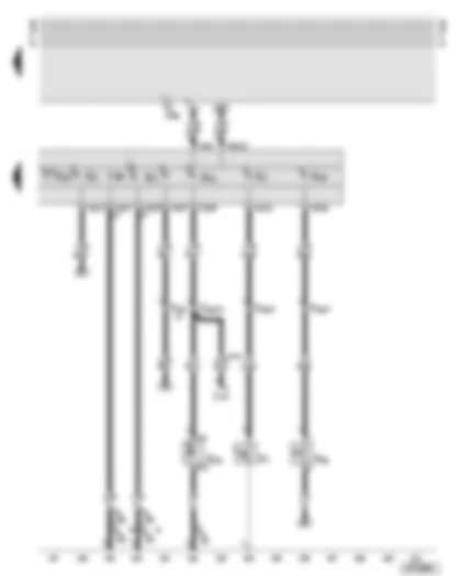
Wiring Diagram AUDI A6 2003 - Motronic control unit - injectors for cylinders 1 - 6 - ignition coils 1 - 4
| J220 | Motronic control unit |
| N30 | Injector, cylinder 1 |
| N31 | Injector, cylinder 2 |
| N32 | Injector, cylinder 3 |
| N33 | Injector, cylinder 4 |
| N70 | Ignition coil 1 with output stage |
| N83 | Injector, cylinder 5 |
| N84 | Injector, cylinder 6 |
| N127 | Ignition coil 2 with output stage |
| N291 | Ignition coil 3 with output stage |
| N292 | Ignition coil 4 with output stage |
| P | Spark plug connector |
| Q | Spark plugs |
| S232 | Fuse 32 in fuse box |
| T10n | 10-pin connector, orange, connector point, electronics box, plenum chamber |
| 85 | Earth connection -1-, in engine compartment wiring harness |
| 132 | Earth connection -3-, in engine compartment wiring harness |
| D23 | Connection (via fuse 229), in front right wiring harness |
| D95 | Connection (injectors), in engine compartment wiring harness |
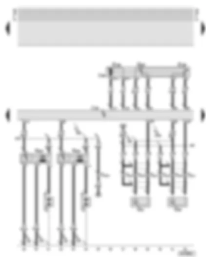
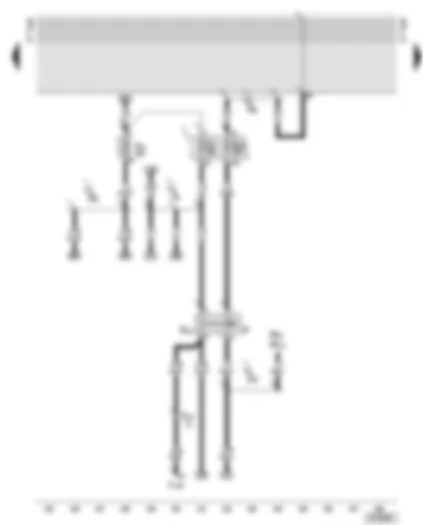
Wiring Diagram AUDI A6 2003 - Motronic control unit - knock sensors - throttle valve module - ignition coils 5 and 6
| G61 | Knock sensor 1 |
| G66 | Knock sensor 2 |
| G186 | Throttle valve drive (electric power control) |
| G187 | Throttle valve drive angle sender -1- (electric power control) |
| G188 | Throttle valve drive angle sender -2- (electric power control) |
| J220 | Motronic control unit |
| J338 | Throttle valve module |
| N323 | Ignition coil -5- with final output stage |
| N324 | Ignition coil -6- with final output stage |
| P | Spark plug connector |
| Q | Spark plugs |
| T3x | 3-pin connector, blue, at knock sensor 1 |
| T3y | 3-pin connector, blue, at knock sensor 2 |
| T10n | 10-pin connector, orange, connector point, electronics box, plenum chamber |
| 85 | Earth connection -1-, in engine compartment wiring harness |
| 132 | Earth connection -3-, in engine compartment wiring harness |
| 220 | Earth connection (sender earth), in engine wiring harness |
| D23 | Connection (via fuse 229), in front right wiring harness |
| D102 | Connection -2-, in engine compartment wiring harness |
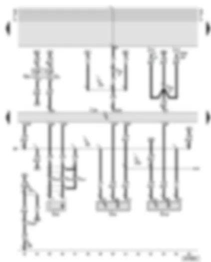
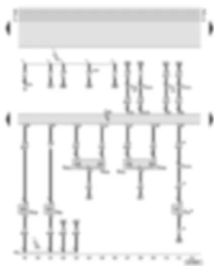
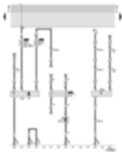
Wiring Diagram AUDI A6 2003 - Motronic control unit - engine speed sender - coolant temperature senders - Hall senders
| G2 | Coolant temperature sender |
| G28 | Engine speed sender |
| G40 | Hall sender |
| G62 | Coolant temperature sender |
| G163 | Hall sender 2 |
| J217 | Automatic gearbox control unit |
| J220 | Motronic control unit |
| T3w | 3-pin connector, grey, on engine speed sender |
| T10p | 10-pin connector, black, connector point, electronics box, plenum chamber |
| T20d | 20-pin connector, black, on automatic gearbox control unit |
| 220 | Earth connection (sender earth), in engine wiring harness |
| 269 | Earth connection (sender earth) -1-, in dash panel wiring harness |
| 316 | Earth connection (sender earth -2-), in engine wiring harness |
| D75 | Positive (+) connection -2- (30), in engine compartment wiring harness |
| D141 | Connection (5V), in engine compartment wiring harness |
| * | Models with automatic gearbox: multitronic® 01J, up to model year 2003 |
| ** | Models with automatic gearbox: multitronic® 01J, from model year 2004 onwards |
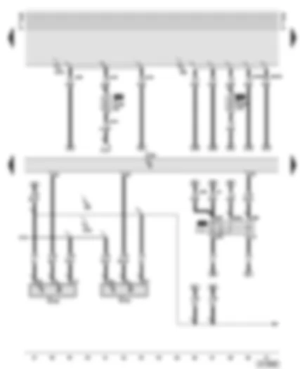
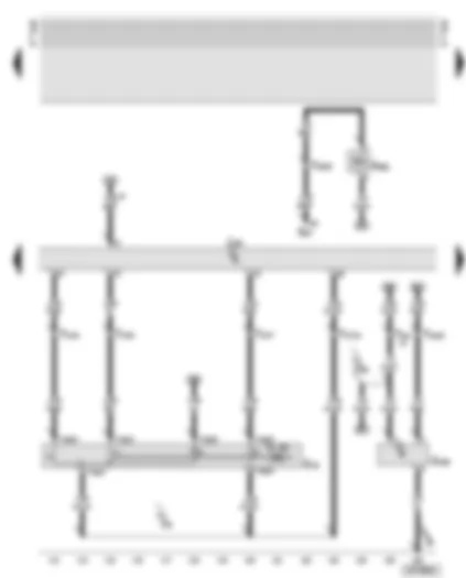
Wiring Diagram AUDI A6 2003 - Motronic control unit - Motronic current supply relay - Hall senders
| G300 | Hall sender 3 |
| G301 | Hall sender 4 |
| J217 | Automatic gearbox control unit |
| J220 | Motronic control unit |
| J271 | Motronic current supply relay |
| S199 | Fuse -1- (15) |
| S282 | Engine electronics fuse |
| 200 | Earth connection (screening), in engine compartment wiring harness |
| D52 | Positive (+) connection (15a), in engine compartment wiring harness |
| D141 | Connection (5V), in engine compartment wiring harness |
| D173 | Connection (87), in engine compartment wiring harness |
| * | Models without automatic gearbox: multitronic® 01J |
| ** | Models with automatic gearbox: multitronic® 01J |
| *** | Only applies to models for countries with hot climate |
Wiring Diagram AUDI A6 2003 - Motronic control unit - fuel pump relay - lambda probes
| G39 | Lambda probe |
| G108 | Lambda probe 2 |
| J17 | Fuel pump relay |
| J220 | Motronic control unit |
| N321 | Exhaust flap 1 valve |
| S234 | Fuse 34 in fuse box |
| T2dh | 2-pin connector, black, connector point, A pillar, right |
| T6as | 6-pin connector, black, for lambda probe |
| T6av | 6-pin connector, black, for lambda probe 2 |
| T10n | 10-pin connector, orange, connector point, electronics box, plenum chamber |
| T10p | 10-pin connector, black, connector point, electronics box, plenum chamber |
| T17i | 17-pin connector, white, connector point, electronics box, plenum chamber |
| Z19 | Lambda probe heater |
| Z28 | Lambda probe 2 heater |
| 200 | Earth connection (screening), in engine compartment wiring harness |
| D22 | Connection (via fuse 234), in front right wiring harness |
| * | Models with front-wheel drive |
Wiring Diagram AUDI A6 2003 - Motronic control unit - air mass meter - lambda probes downstream of catalytic converter
| G70 | Air mass meter |
| G130 | Lambda probe downstream of catalytic converter |
| G131 | Lambda probe 2 downstream of catalytic converter |
| J220 | Motronic control unit |
| S229 | Fuse 29 in fuse box |
| T4s | 4-pin connector, green, for lambda probe 1 downstream of catalytic converter |
| T4t | 4-pin connector, brown, for lambda probe 2 downstream of catalytic converter |
| T17i | 17-pin connector, white, connector point, electronics box, plenum chamber |
| Z29 | Lambda probe 1 heater, downstream of catalytic converter |
| Z30 | Lambda probe 2 heater, downstream of catalytic converter |
| D22 | Connection (via fuse 234), in front right wiring harness |
| * | Models without automatic gearbox: multitronic® 01J |
| ** | Models with automatic gearbox: multitronic® 01J |
Wiring Diagram AUDI A6 2003 - Motronic control unit - camshaft timing adjustment valves - intake manifold change-over valve - clutch pedal switch
| D | Ignition/starter switch |
| F36 | Clutch pedal switch |
| J220 | Motronic control unit |
| N80 | Activated charcoal filter system solenoid valve 1 (pulsed) |
| N156 | Intake manifold change-over valve |
| N205 | Inlet camshaft timing adjustment valve -1- |
| N208 | Inlet camshaft timing adjustment valve -2- |
| N318 | Exhaust camshaft timing adjustment valve -1- |
| N319 | Exhaust camshaft timing adjustment valve -2- |
| T10n | 10-pin connector, orange, connector point, electronics box, plenum chamber |
| T17i | 17-pin connector, white, connector point, electronics box, plenum chamber |
| T17k | 17-pin connector, red, connector point, electronics box, plenum chamber |
| A2 | Positive (+) connection (15), in dash panel wiring harness |
| D22 | Connection (via fuse 234), in front right wiring harness |
| * | Models with manual gearbox |
| ** | Models with automatic gearbox |
Wiring Diagram AUDI A6 2003 - Motronic control unit - cruise control system - compressor regulating valve - oil level thermo sender - service interval
| E45 | Cruise control system switch |
| E87 | Air conditioning system operating and display unit |
| G266 | Oil level thermo sender, service interval |
| J220 | Motronic control unit |
| N280 | Air conditioning system compressor regulating valve |
| T10o | 10-pin connector, brown, connector point, electronics box, plenum chamber |
| T10p | 10-pin connector, black, connector point, electronics box, plenum chamber |
| T10q | 10-pin connector, black, on cruise control system switch |
| T17i | 17-pin connector, white, connector point, electronics box, plenum chamber |
| 85 | Earth connection -1-, in engine compartment wiring harness |
| A16 | Connection (cruise control system), in dash panel wiring harness |
| D136 | Positive (+) connection -2- (15a), in engine compartment wiring harness |
| # | Only applies to models for countries with hot climate |
Wiring Diagram AUDI A6 2003 - Motronic control unit - accelerator pedal position senders
| E3 | Hazard warning light switch |
| G79 | Accelerator pedal position sender |
| G185 | Accelerator pedal position sender -2- |
| J217 | Automatic gearbox control unit |
| J220 | Motronic control unit |
| J234 | Airbag control unit |
| T10o | 10-pin connector, brown, connector point, electronics box, plenum chamber |
| T17i | 17-pin connector, white, connector point, electronics box, plenum chamber |
| T17k | 17-pin connector, red, connector point, electronics box, plenum chamber |
| T17m | 17-pin connector, blue, connector point, A pillar, right |
| T20d | 20-pin connector, black, on automatic gearbox control unit |
| A121 | Connection (high bus), in dash panel wiring harness |
| A122 | Connection (low bus), in dash panel wiring harness |
| A125 | Connection (crash signal), in dash panel wiring harness |
| • | CAN bus (data wire) |
| * | Models with automatic gearbox 01V |
| ** | Models with automatic gearbox: multitronic® 01J |
| # | Up to model year 2003 |
| ## | From model year 2004 onwards |
Wiring Diagram AUDI A6 2003 - Motronic control unit - secondary air pump - brake servo relay - vacuum pump for brakes
| G294 | Brake servo pressure sensor |
| J220 | Motronic control unit |
| J299 | Secondary air pump relay |
| J569 | Brake servo relay |
| N112 | Secondary air inlet valve |
| S130 | Secondary air pump fuse |
| S279 | Hydraulic pump relay fuse |
| T17i | 17-pin connector, white, connector point, electronics box, plenum chamber |
| T17k | 17-pin connector, red, connector point, electronics box, plenum chamber |
| V101 | Secondary air pump motor |
| V192 | Vacuum pump for brakes |
| 12 | Earth point, in engine compartment, left |
| 85 | Earth connection -1-, in engine compartment wiring harness |
| A32 | Positive (+) connection (30), in dash panel wiring harness |
| * | Only models with automatic gearbox |
Wiring Diagram AUDI A6 2003 - Brake light switch - cruise control system brake pedal switch
| F | Brake light switch |
| F47 | Cruise control system brake pedal switch |
| J104 | ABS with EDL control unit |
| M9 | Brake light bulb, left |
| M10 | Brake light bulb, right |
| S5 | Fuse in fuse box |
| S7 | Fuse in fuse box |
| S13 | Fuse in fuse box |
| T17f | 17-pin connector, black, in 8-point relay carrier, behind driver's storage compartment |
| A18 | Connection (54), in dash panel wiring harness |
| A20 | Connection (15a), in dash panel wiring harness |
| A52 | Positive (+) connection 2 (30), in dash panel wiring harness |
| J9 | Connection -1- (15a), in ABS wiring harness |
Wiring Diagram AUDI A6 2003 - Engine cooling
| E87 | Control and display unit for air conditioner |
| G65 | High pressure sender |
| J151 | Continued coolant circulation relay |
| J293 | Radiator fan control unit, in engine compartment, front left |
| S42 | Radiator fan single fuse |
| S142 | Radiator fan control unit fuse |
| T14a | 14-pin connector, black, in engine compartment, front left |
| T17h | 17-pin connector, brown, connector point, A pillar, left |
| V7 | Radiator fan |
| V51 | Continued coolant circulation pump |
| 44 | Earth point, lower part of left A pillar |
| 85 | Earth connection -1-, in engine compartment wiring harness |
| 193 | Earth connection -1-, in radiator fan wiring harness |
| * | Only applies to models for countries with hot climate |
| ** | Applies to 400 W radiator fan |
| *** | Applies to 600 W radiator fan |
Wiring Diagram AUDI A6 2003 - Dash panel insert - fuel pump
| G | Fuel gauge sender |
| G1 | Fuel gauge |
| G6 | Fuel pump (pre-supply pump) |
| G169 | Fuel gauge sender -2- |
| G237 | Fuel gauge sender -3- |
| J285 | Control unit with display in dash panel insert |
| K2 | Alternator warning lamp |
| S228 | Fuse 28 in fuse box |
| T10f | 10-pin connector, brown, connector point, A pillar, left |
| T10ba | 10-pin connector, blue, connector point, A pillar, left |
| T16a | 16-pin connector, diagnosis connection |
| T32 | 32-pin connector, blue, on dash panel insert |
| T32a | 32-pin connector, green, on dash panel insert |
| 86 | Earth connection -1-, in rear wiring harness |
| 269 | Earth connection (sender earth) -1-, in dash panel wiring harness |
| A76 | Connection (diagnosis wire K), in dash panel wiring harness |
| * | Models with front-wheel drive |
| ** | Models with four-wheel drive |
| *** | Wiring in fuel tank |
| # | Sender earth output |
Wiring Diagram AUDI A6 2003 - Dash panel insert - speedometer - oil pressure warning lamp - coolant temperature/coolant shortage warning lamp
| F1 | Oil pressure switch |
| F66 | Coolant shortage indicator switch |
| G3 | Coolant temperature gauge |
| G5 | Rev. counter |
| G21 | Speedometer |
| G22 | Speedometer sender (Hall sender, on gearbox) |
| J217 | Automatic gearbox control unit |
| J285 | Control unit with display in dash panel insert |
| K3 | Oil pressure warning lamp |
| K28 | Coolant temperature/coolant shortage warning lamp |
| K83 | Fault warning lamp for self-diagnosis/exhaust emissions |
| T10p | 10-pin connector, black, connector point, electronics box, plenum chamber |
| T32 | 32-pin connector, blue, on dash panel insert |
| T32a | 32-pin connector, green, on dash panel insert |
| 85 | Earth connection -1-, in engine compartment wiring harness |
| 135 | Earth connection -2-, in dash panel wiring harness |
| 199 | Earth connection -3-, in dash panel wiring harness |
| A108 | Connection (speed signal), in dash panel wiring harness |
| * | Both possible |
| ** | Models with automatic gearbox: multitronic® 01J |
Can't find your car? Check -> DiagnostData.com!

