Single connector, for telepass aerial, in driver's door
T2u
2-pin connector, for telepass supply, in driver's door
T20a
20-pin connector, black, A pillar, left
369
Earth connection -4-, in main wiring harness
B298
Positive (+) connection -2- (30), in main wiring harness
B302
Positive (+) connection -6- (30), in main wiring harness
B303
Positive (+) connection -7- (30), in main wiring harness
*
Only models for Italy
**
In exterior mirror, driver's side
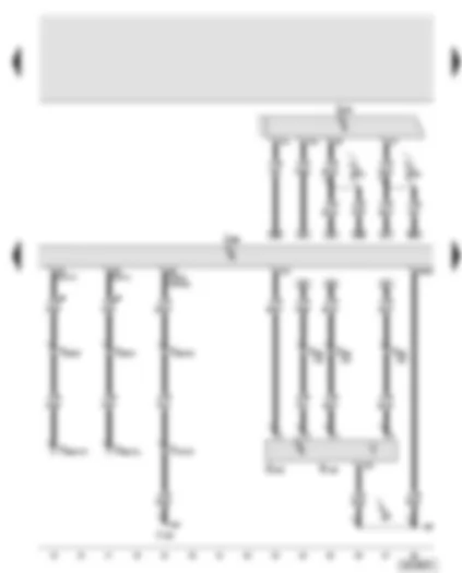
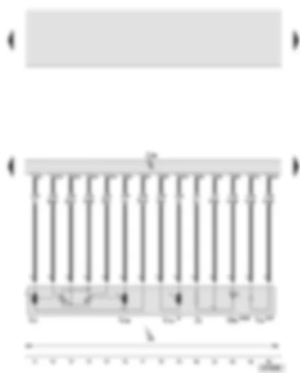
Wiring Diagram AUDI A8 2003 - Door control unit - driver's side - exterior door handle touch sensor - driver's side - driver's side aerial for entry and start authorisation - entry and start authorisation control unit
Driver's side aerial for entry and start authorisation
T17s
17-pin connector, brown, under driver's seat
T20a
20-pin connector, black, A pillar, left
T46a
46-pin connector, black, CAN separating connector, left
267
Earth connection -2-, in door wiring harness - driver's side
B371
Connection -1- (aerial), in main wiring harness
B372
Connection -2- (aerial), in main wiring harness
•
CAN bus (data wire)
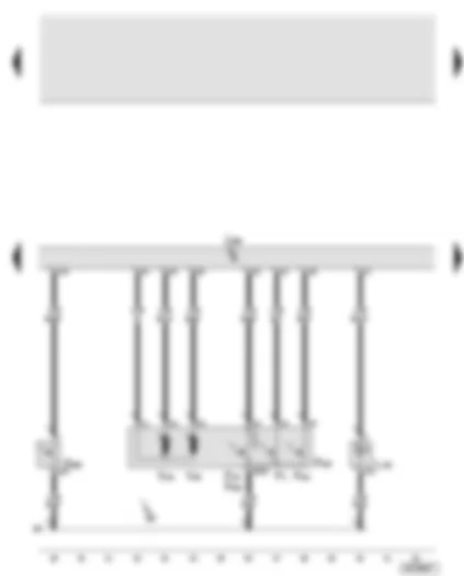
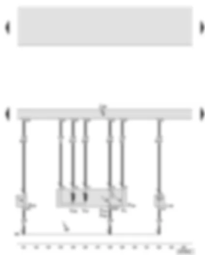
Wiring Diagram AUDI A8 2003 - Door control unit - driver's side - exterior door handle central locking button - driver's side - front left exterior door handle illumination - central locking lock unit - driver's side
Wiring Diagram AUDI A8 2003 - Door control unit - driver's side - mirror adjustment switch - mirror adjustment change-over switch - mirror with folding function - adjustment switch - interior monitor switch - alarm system off switch - interior monitor sender/receiver module 1
8-pin connector, black, near interior light, front
T17r
17-pin connector, in driver's door
T46b
46-pin connector, black, CAN separating connector, right
304
Earth connection -3-, in door wiring harness - driver's side
•
CAN bus (data wire)
Wiring Diagram AUDI A8 2003 - Door control unit - driver's side - mirror adjustment motors - heated exterior mirror - driver's side - automatic anti-dazzle exterior mirror - driver's side - entry light in exterior mirror
Automatic anti-dazzle exterior mirror, driver's side
W52
Entry light in exterior mirror, driver's side
Z4
Heated exterior mirror, driver's side
304
Earth connection -3-, in door wiring harness - driver's side
*
Mirror with retraction function
**
With automatic anti-dazzle exterior mirror
***
With entry light in exterior mirror
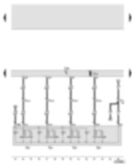
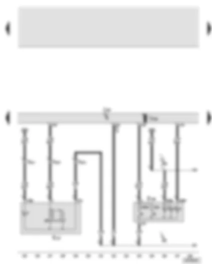
Wiring Diagram AUDI A8 2003 - Door control unit - driver's side - central locking warning lamp -SAFE- - interior locking switch - driver's side - door warning lamp - driver's side - front left entry light
Earth connection -3-, in door wiring harness - driver's side
R52
Connection (58s), in door wiring harness - driver's side
R66
Positive (+) connection (central locking), in door wiring harness - driver's side
*
Switch earth output
Wiring Diagram AUDI A8 2003 - Door control unit - driver's side - fuel tank flap release button - rear lid remote release button - illumination of driver's door storage compartment
Positive (+) connection (30), in main wiring harness
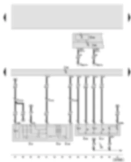
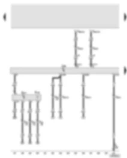
Wiring Diagram AUDI A8 2003 - Door control unit - front passenger's side - entry and start authorisation control unit - exterior door handle touch sensor - front passenger's side - front passenger's side aerial for entry and start authorisation
Seat adjustment with memory control unit, front passenger
R135
Front passenger's side aerial for entry and start authorisation
T17t
17-pin connector, brown, under front passenger's seat
T20b
20-pin connector, black, A pillar, right
T46b
46-pin connector, black, CAN separating connector, right
268
Earth connection -2-, in door wiring harness - front passenger's side
B373
Connection -3- (aerial), in main wiring harness
B374
Connection -4- (aerial), in main wiring harness
•
CAN bus (data wire)
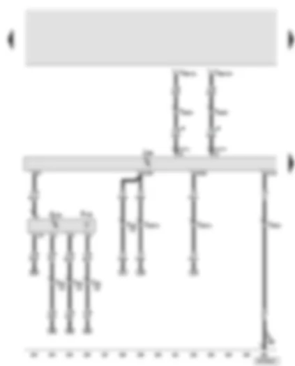
Wiring Diagram AUDI A8 2003 - Door control unit - front passenger's side - central locking button - front right exterior door handle illumination - central locking lock unit - front passenger's side
Central locking motor (Safe), front passenger's door
268
Earth connection -2-, in door wiring harness - front passenger's side
Wiring Diagram AUDI A8 2003 - Door control unit - front passenger's side - electric window switch in front passenger's door - interior locking switch - front passenger's side
Earth connection -3-, in door wiring harness - front passenger's side
R53
Connection (58s), in door wiring harness - front passenger's side
*
Switch earth output
Wiring Diagram AUDI A8 2003 - Door control unit - front passenger's side - central locking warning lamp -SAFE- (front passenger) - front right entry light - door warning lamp - front passenger's side - illumination of front passenger's door storage compartment
Central locking warning lamp -SAFE-, front passenger
L109
Door opening illumination, front passenger's side
L161
Illumination of front passenger's door storage compartment
L165
Ambient lighting for front passenger's door
T2k
2-pin connector, in front passenger's door
T2ae
2-pin connector, on ambient lighting voltage converter
T2af
2-pin connector, on ambient lighting voltage converter
T17q
17-pin connector, in front passenger's door
T20b
20-pin connector, black, A pillar, right
W32
Front right entry light
W36
Door warning lamp, front passenger's side
303
Earth connection -3-, in door wiring harness - front passenger's side
R53
Connection (58s), in door wiring harness - front passenger's side
Wiring Diagram AUDI A8 2003 - Door control unit - front passenger's side - mirror adjustment motors - heated exterior mirror - front passenger's side - entry light in exterior mirror - front passenger's side
Automatic anti-dazzle exterior mirror, front passenger's side
W53
Entry light in exterior mirror, front passenger's side
Z5
Heated exterior mirror, front passenger's side
*
Mirror with retraction function
**
With automatic anti-dazzle exterior mirror
***
With entry light in exterior mirror
Wiring Diagram AUDI A8 2003 - Rear left door control unit - rear left exterior door handle touch sensor - entry and start authorisation - driver's side rear aerial
Entry and start authorisation, driver's side rear aerial
T20c
20-pin connector, black, B pillar, left
T46a
46-pin connector, black, CAN separating connector, left
367
Earth connection -2-, in main wiring harness
•
CAN bus (data wire)
Wiring Diagram AUDI A8 2003 - Rear left door control unit - rear left exterior door handle illumination - rear left exterior door handle central locking button - rear left central locking lock unit
2-pin connector, on ambient lighting voltage converter
T2af
2-pin connector, on ambient lighting voltage converter
W33
Rear left entry light
W37
Door warning lamp, rear left
408
Earth connection -3-, in rear left door wiring harness
R54
Connection (58s), in rear left door wiring harness
*
Switch earth output
Wiring Diagram AUDI A8 2003 - Rear left door control unit - rear left electric window switch (in door) - rear left ashtray light bulb - rear left electric window motor - illumination of rear left door storage compartment
Illumination of rear left door storage compartment
T4f
4-pin connector, in rear left door
T4h
4-pin connector, in rear left door
V26
Electric window motor, rear left
408
Earth connection -3-, in rear left door wiring harness
R54
Connection (58s), in rear left door wiring harness
Wiring Diagram AUDI A8 2003 - Rear right door control unit - rear right exterior door handle touch sensor - entry and start authorisation - front passenger's side rear aerial
Entry and start authorisation, front passenger's side rear aerial
T20d
20-pin connector, black, B pillar, right
T46b
46-pin connector, black, CAN separating connector, right
368
Earth connection -3-, in main wiring harness
•
CAN bus (data wire)
Wiring Diagram AUDI A8 2003 - Rear right door control unit - rear right exterior door handle central locking button - rear right central locking lock unit
Earth connection -2-, in rear right door wiring harness
*
Switch earth output
**
Models without entry and start authorisation
***
Models with entry and start authorisation
Wiring Diagram AUDI A8 2003 - Rear right door control unit - rear right entry light - rear right door warning lamp - rear right interior locking switch - rear right door opening illumination - ambient lighting for rear right door
2-pin connector, on ambient lighting voltage converter
T2af
2-pin connector, on ambient lighting voltage converter
W34
Rear right entry light
W38
Door warning lamp, rear right
409
Earth connection -3-, in rear right door wiring harness
R55
Connection (58s), in rear right door wiring harness
*
Switch earth output
Wiring Diagram AUDI A8 2003 - Rear right door control unit - rear right electric window motor - rear right electric window switch (in door) - rear right ashtray light bulb - illumination of rear right door storage compartment
46-pin connector, black, CAN separating connector, right
378
Earth connection -13-, in main wiring harness
B165
Positive (+) connection -2- (15), in interior wiring harness
B273
Positive (+) connection (15), in main wiring harness
B299
Positive (+) connection -3- (30), in main wiring harness
B316
Positive (+) connection -2- (30a), in main wiring harness
•
CAN bus (data wire)
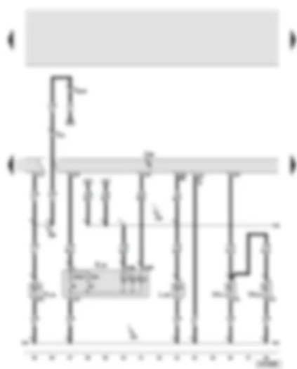
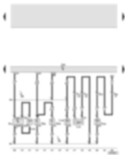
Wiring Diagram AUDI A8 2003 - Convenience system central control unit - rear lid - tank filler flap locking motor - switch in lock cylinder for rear lid anti-theft alarm system/central locking system - release button for rear lid lock cylinder - central locking motor - rear lid - alarm horn
Positive (+) connection (30), in main wiring harness
B300
Positive (+) connection -4- (30), in main wiring harness
B303
Positive (+) connection -7- (30), in main wiring harness
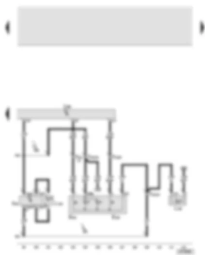
Wiring Diagram AUDI A8 2003 - Convenience system central control unit - rear lid electric release motor - rear lid control unit - power latching system limit switch - luggage compartment - anti-theft/tilt system control unit - power latching control unit
5-pin connector, in luggage compartment, for rear lid power latching system
V120
Rear lid lock motor
V254
Rear lid electric release motor
376
Earth connection -11-, in main wiring harness
378
Earth connection -13-, in main wiring harness
383
Earth connection -18-, in main wiring harness
B476
Connection -12-, in main wiring harness
B487
Connection -23-, in main wiring harness
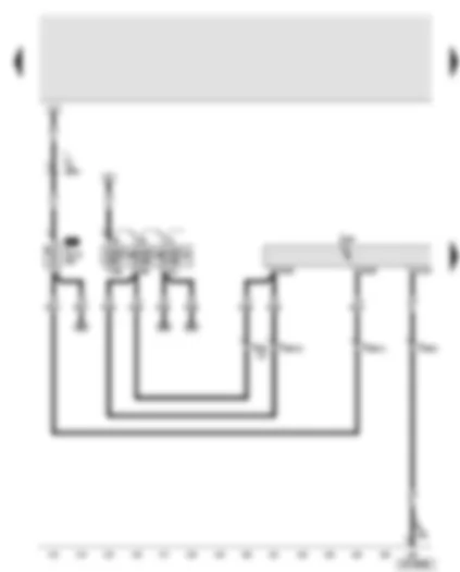
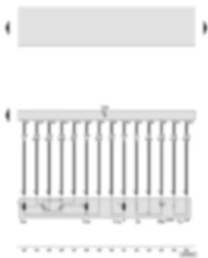
Wiring Diagram AUDI A8 2003 - Convenience system central control unit - luggage compartment light - boot lid light - rear left and rear right footwell illumination
17-pin connector, grey, under front passenger's seat
W18
Luggage compartment light, left
W35
Luggage compartment light, right
W51
Boot lid light
367
Earth connection -2-, in main wiring harness
368
Earth connection -3-, in main wiring harness
371
Earth connection -6-, in main wiring harness
377
Earth connection -12-, in main wiring harness
378
Earth connection -13-, in main wiring harness
B476
Connection -12-, in main wiring harness
M43
Connection -3-, in driver's seat wiring harness
M53
Connection -3-, in front passenger's seat wiring harness
Wiring Diagram AUDI A8 2003 - Onboard power supply control unit - bonnet contact switch - left footwell light - centre console illumination - right footwell light
J431 - Headlight range control regulator V48 - Left headlight range control motor V49 - Right headlight range control motor
15
5
-
SB5 - Fuse 5 on fuse holder B
10 A 5 A¹)
-
J285 - Control unit with display in dash panel insert J533-Data bus diagnostic interface²)
30
6
-
SB6 - Fuse 6 on fuse holder B
10 A
-
J527 - Steering column electronics control unit
30
7
-
SB7 - Fuse 7 on fuse holder B
5 A
-
T16 - 16-pin connector, diagnostic connector
30
8
-
SB8 - Fuse 8 on fuse holder B
5 A
-
G266 - Oil level and oil temperature sender¹) T16 - Connector, 16-pin diagnostic connector
15
9
-
SB9 - Fuse 9 on fuse holder B
10 A 5 A¹)
-
J104 - ABS control unit J527 - Steering column electronics control unit
15
10
-
SB10 - Fuse 10 on fuse holder B
5 A
-
G266 - oil level and oil temperature sender²) J533 - Data bus diagnostic interface¹)
15
11
-
SB11 - Fuse 11 on fuse holder B
10 A
J759 - Lane departure warning control unit³)
15
12
-
SB12 - Fuse 12 on fuse holder B
5 A
-
F - Brake light switch
30
¹) from model year 2004
²) up to model year 2003
³) from September 2007
Audi A8
Fitting Locations
No. 802 / 6
No.
Current Flow Diagram designation
Nominal value
Function/component
Terminal
25
-
SB25 - Fuse 25 on fuse holder B
40 A
-
J400 - Wiper motor control unit
30
26
-
SB26 - Fuse 26 on fuse holder B
15 A³) 30 A²)
-
J608 - Special vehicle control unit³) U18 - 12 V socket 2²) U19 - 12 V socket 3²)
30
27
-
SB27 - Fuse 27 on fuse holder B
25 A
-
J104 - ABS control unit
30
28
-
Vacant
29
-
SB29 - Fuse 29 on fuse holder B
1 A
-
- Switch illumination
58s
30
-
Vacant
31
-
SB31 - Fuse 31 on fuse holder B
30 A
-
J519 - Onboard power supply control unit
30
32
-
SB32 - Fuse 32 on fuse holder B
5 A⁵)
-
J685 - Display unit for front information display and operating unit control unit ⁵)
30
33
-
SB33 - Fuse 33 on fuse holder B
25 A
-
Z42-Rear left footwell heater element
75
34
-
Vacant
35
-
Vacant
36
-
SB36 - Fuse 36 on fuse holder B
5 A
J769 - Lane change assist control unit⁴)
15
37
-
SB37 - Fuse 37 on fuse holder B
15 A
-
J698 - Refrigerator box³)
15
38
-
SB38 - Fuse 38 on fuse holder B
30 A
-
J519 - Onboard power supply control unit
30
39
-
SB39 - Fuse 39 on fuse holder B
15 A 7.5 A¹)
-
J386 - Driver door control unit
30
¹) from model year 2004
²) up to model year 2004
³) from model year 2006
⁴) from September 2007
⁵) from September 2008
Audi A8
Fitting Locations
No. 802 / 8
Audi A8
Fitting Locations
No. 802 / 9
No.
Current Flow Diagram designation
Nominal value
Function/component
Terminal
8
-
SB8 - Fuse 8 on fuse holder B
10 A
-
J544 - Throttle valve module 2 J725 - Turbocharger 2 control unit N144 - Left electrohydraulic engine mounting solenoid valve N205 - Inlet camshaft control valve 1 N208 - Inlet camshaft control valve N213 - Exhaust gas recirculation valve 2 N321 - Exhaust flap 1 valve N382 - Torque rod valve V51 - Continued coolant circulation pump V275 - Intake manifold flap 2 motor
87
9
-
SB9 - Fuse 9 on fuse holder B
5 A
-
J104 - ABS control unit J527 - Steering column electronics control unit
15
10
-
SB10 - Fuse 10 on fuse holder B
10 A
-
J197 - Adaptive suspension control unit
15
11
-
SB11 - Fuse 11 on fuse holder B
10 A
-
J759 - Lane departure warning control unit
15
12
-
SB12 - Fuse 12 on fuse holder B
5 A
7.5 A¹)
-
J523 - Front information display and operating unit control unit J794 - Control unit for information electronics 1¹)
30
13
-
SB13 - Fuse 13 on fuse holder B
10 A
-
J412 - Telephone operating electronics control unit J526 - Mobile telephone operating electronics control unit R36 - Telephone transmitter and receiver unit R115 - Chip card reader for telephone - Preparation for mobile telephone
30
5 A¹)
-
R86 - Aerial amplifier for mobile telephone¹) R126 - Telephone bracket¹)
30
¹) from September 2008
Audi A8
Fitting Locations
No. 802 / 11
No.
Current Flow Diagram designation
Nominal value
Function/component
Terminal
28
-
SB28 - Fuse 28 on fuse holder B
5 A
-
J17 - Fuel pump relay J49 - Electric fuel pump 2 relay J248 - Diesel direct injection system control unit J569 - Brake servo relay J623 - Engine control unit
15
29
-
SB29 - Fuse 29 on fuse holder B
15 A
-
N30.. - Injector
87
30
-
SB30 - Fuse 30 on fuse holder B
30 A
-
N...- Ignition coils with output stage J623 - Engine control unit
87
31
-
SB31 - Fuse 31 on fuse holder B
20 A
40 A
-
G23 - Right fuel pump N115 - Active charcoal filter system solenoid valve 2 (USA) V144 - Fuel system diagnostic pump (USA) J538 - Fuel pump control unit
87
32
-
SB32 - Fuse 32 on fuse holder B
10 A 5 A
-
J217 - Automatic gearbox control unit 01J, 01T J217 - Automatic gearbox control unit 09E, 09L
F189 - Tiptronic switch F305 - Gear selector position P switch N110 - Selector lever lock solenoid
15
4
-
SC4 - Fuse 4 on fuse holder C
15 A
-
J217 - Automatic gearbox control unit 01J/01T
87
5
-
SC5-Fuse 5 on fuse holder C
15 A
-
G70 - Air mass meter J299 - Secondary air pump relay J338 - Throttle valve module J724 - Turbocharger 1 control unit N18 - Exhaust gas recirculation valve N112 - Secondary air inlet valve N145 - Right electrohydraulic engine mounting solenoid valve N382 - Torque rod valve V157 - Intake manifold flap motor
R41 - CD changer R92 - CD ROM drive R129 - Video recorder / DVD player
30
15
-
SC15 - Fuse 15 on fuse holder C
5 A
-
J644 - Energy management control unit
30
16
-
SC16 - Fuse 16 on fuse holder C
5 A 7.5 A³)
-
N79 - Heater element for crankcase breather
87
17
-
SC17 - Fuse 17 on fuse holder C
5 A¹)
-
- Vacant V7 - Radiator fan V177 - Radiator fan 2
87
18
-
SC18 - Fuse 18 on fuse holder C
5 A
-
- Vacant (from January 2003) J234 - Airbag control unit²) J706 - Seat occupied recognition control unit (only USA)²) L34 - Map reading light bulb (up to December 2002)
15
19
-
SC19 - Fuse 19 on fuse holder C
5 A
-
G70 - Air mass meter
15
20
-
SC20 - Fuse 20 on fuse holder C
5 A
-
J526 - Telephone and telematics control unit (USA) J672 - Driver seat ventilation control unit J673 - Front passenger seat ventilation control unit
75
21
-
SC21 - Fuse 21 on fuse holder C
15 A 5 A
-
J248 - Diesel direct injection system control unit J271 - Motronic current supply relay J623 - Engine control unit


 - rear left ashtray light bulb - rear left electric window motor - illumination of rear left door storage compartment")


 - rear right ashtray light bulb - illumination of rear right door storage compartment")


")


 on fuse holder, on right in luggage compartment, from model year 2004")
 on fuse holder, on left in luggage compartment, up to model year 2003")
 on fuse holder, on left in luggage compartment, from model year 2004")


