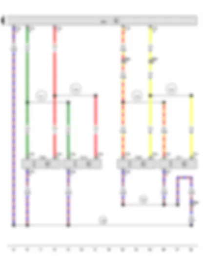
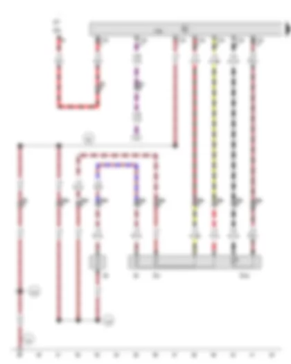
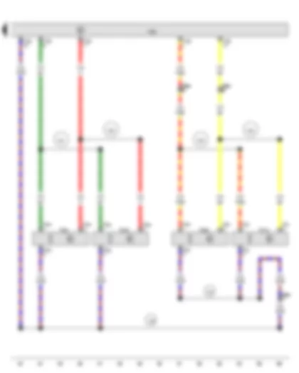
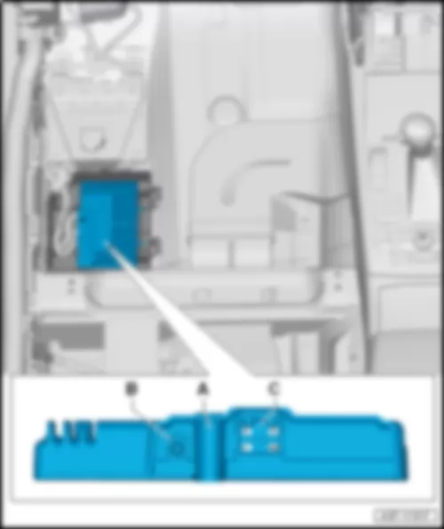
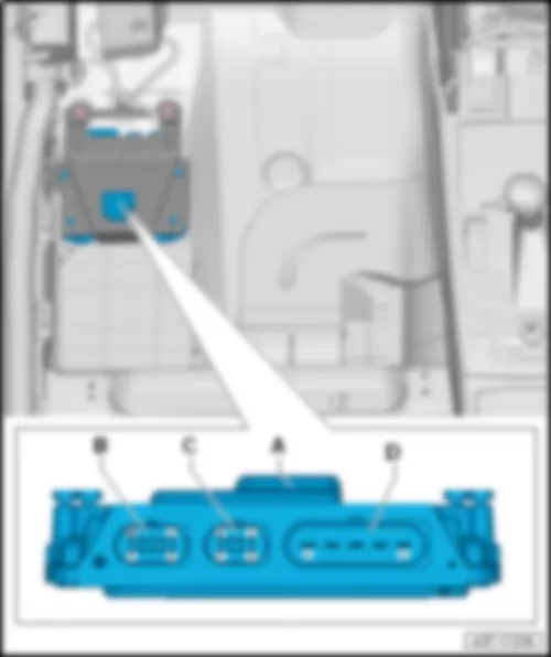
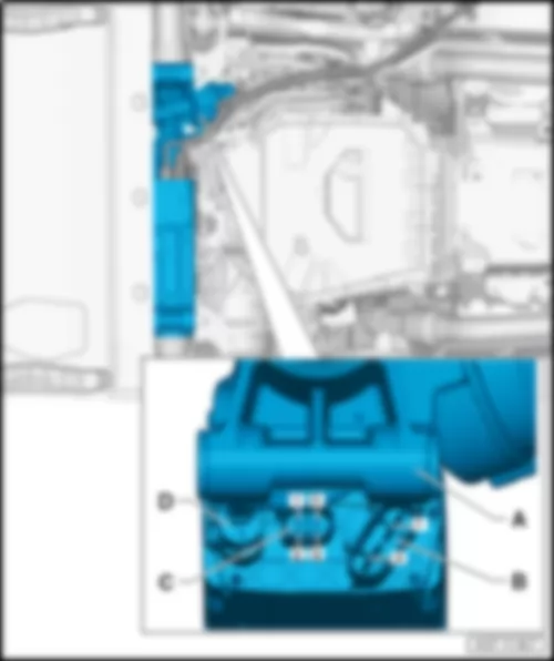
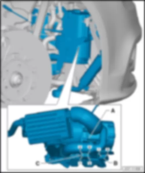
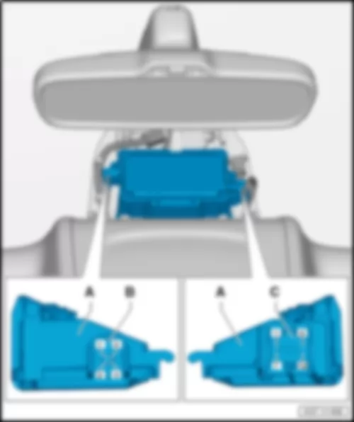
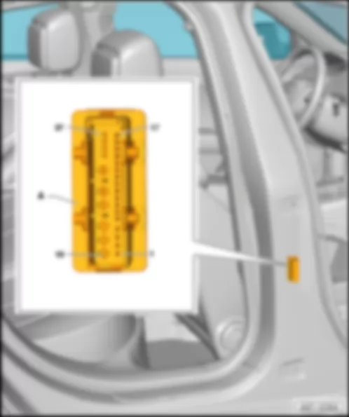
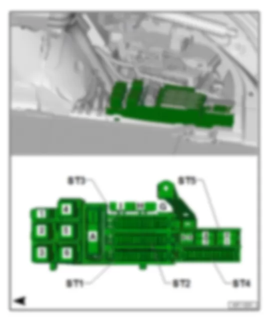
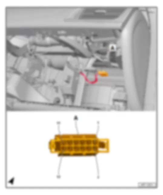
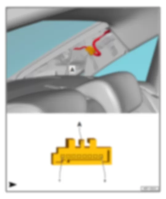
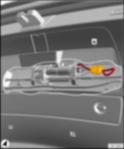
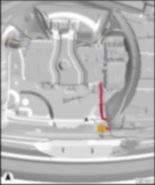
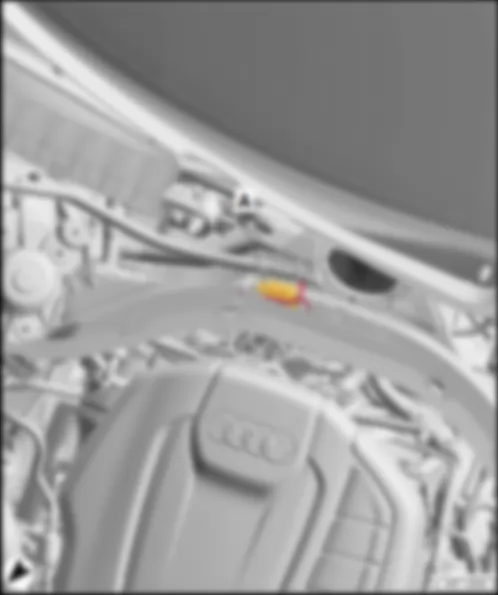
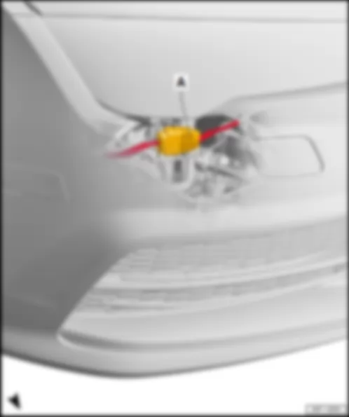
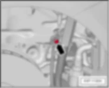
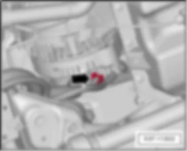
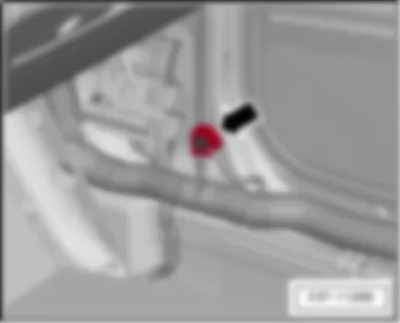
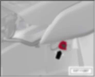
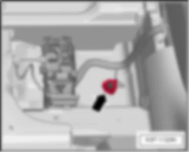
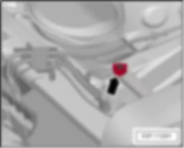
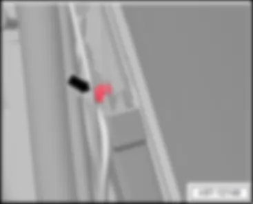
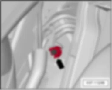
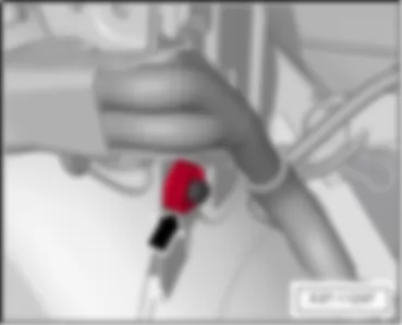
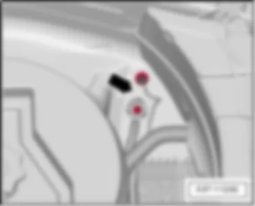
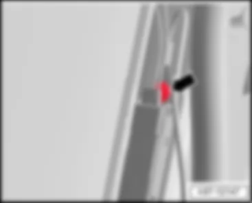
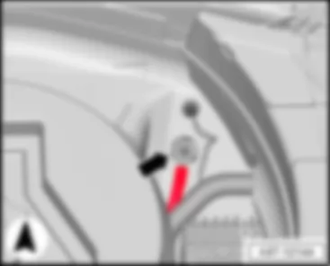
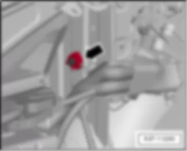
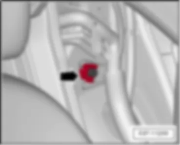
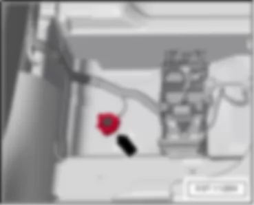
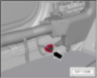
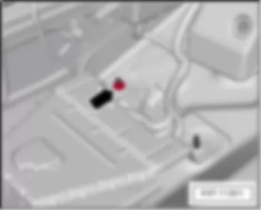
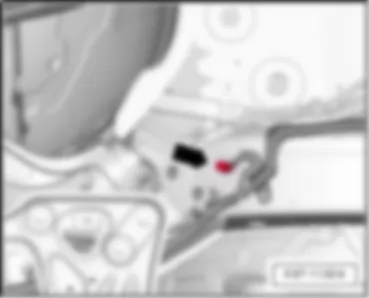
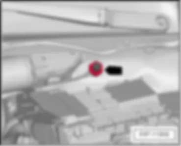
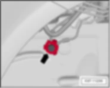
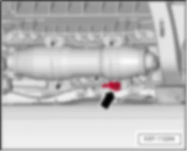
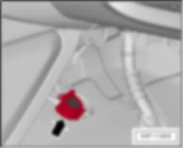
| A - | Image processing control unit -J851- | | C - | 5-pin connector -T5i- , black, camera control unit -J852- |
| A - | Image processing control unit -J851- | | B - | 12-pin connector -T12i- , black | | C - | 5-pin connector -T5i- , black, camera control unit -J852- |
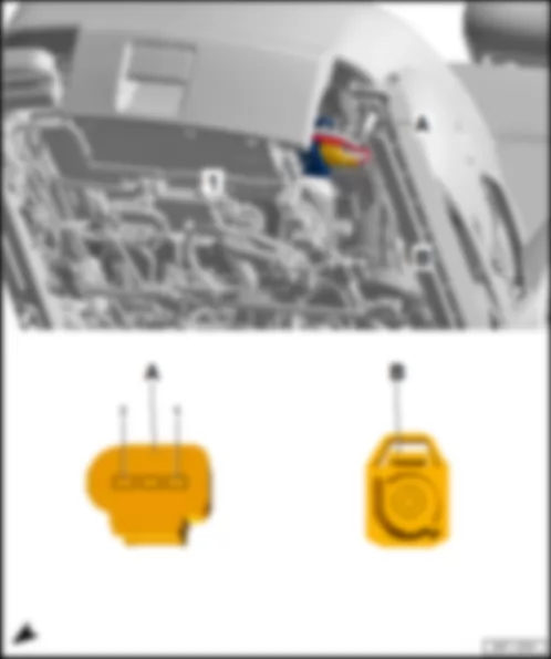
AUDI A7 2014 Fitting location, airbag control unit J234 | A - | Airbag control unit -J234- | | B - | 100-pin connector -T100- , yellow |
AUDI A7 2014 Fitting location, control unit for sensor electronics J849 | A - | Control unit for sensor electronics -J849- | | B - | 50-pin connector -T50- , ivory |
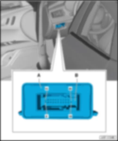
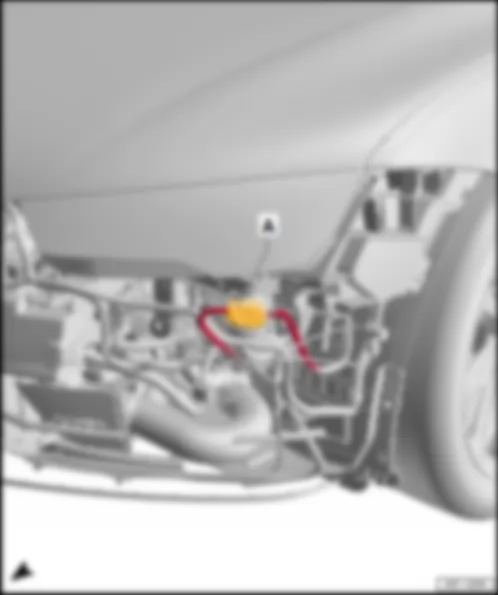
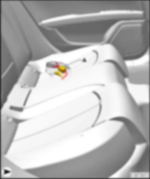
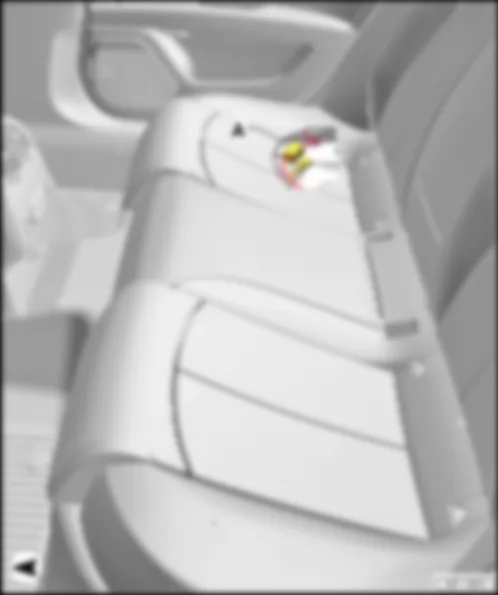
AUDI A7 2014 Fitting location, control unit for night vision system J853 Fitting location, control unit for night vision system -J853- |
| Under driver seat, left-hand drive. | | Under front passenger seat, right-hand drive. | | | | | A - | Control unit for night vision system -J853- | | C - | 12-pin connector -T12b- , black |
AUDI A7 2014 Fitting location, active steering control unit J792 Fitting location, active steering control unit -J792- |
| Fitting location, left-hand drive | | | | | A - | Active steering control unit -J792- | | C - | 8-pin connector -T8m- , black | | D - | 5-pin connector -T5k- , black, Active steering motor -V477- |
| A - | Active steering control unit -J792- | | B - | 10-pin connector -T10c- , black | | C - | 8-pin connector -T8m- , black | | D - | 5-pin connector -T5k- , black, Active steering motor -V477- |
AUDI A7 2014 Fitting location, 16-pin connector -T16- , diagnostic connector |
| A - | 16-pin connector -T16- , black |
| A - | 16-pin connector -T16- , black |
AUDI A7 2014 Fitting location, headlight range control unit J431 Fitting location, headlight range control unit -J431- |
| Control unit for cornering light and headlight range control -J745- , for models with cornering light | | Fitting location, left-hand drive | | Behind left stowage compartment on driver side. | | | | | A - | Headlight range control unit -J431- | | A - | Control unit for cornering light and headlight range control -J745- | | q | models with cornering light | | B - | 26-pin connector -T26a- , black |
| A - | Headlight range control unit -J431- | | A - | Control unit for cornering light and headlight range control -J745- | | q | models with cornering light | | B - | 26-pin connector -T26a- , black |
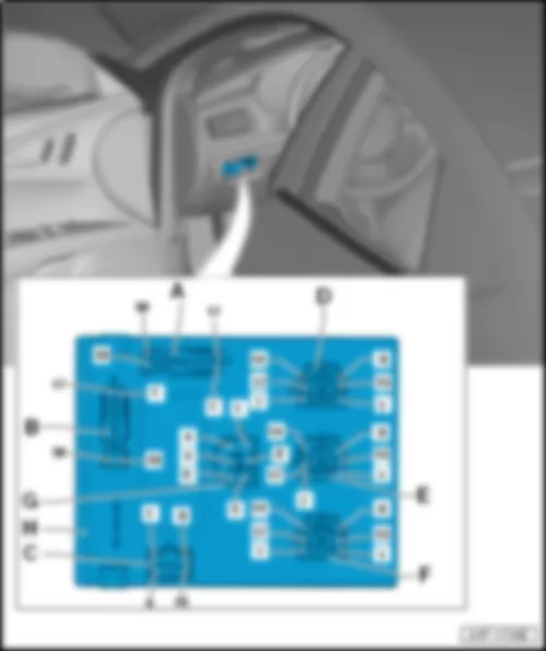
AUDI A7 2014 Fitting location, onboard supply control unit J519 Fitting location, onboard supply control unit -J519- |
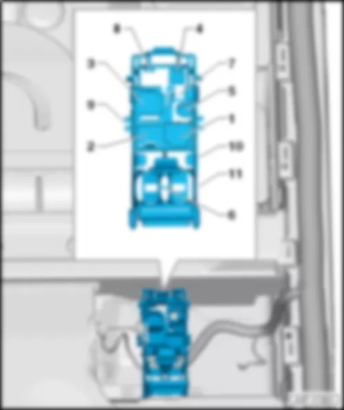
| Fitting location, left-hand drive | | Behind left stowage compartment on driver side. | | | | | B - | 32-pin connector -T32a- , black | | D - | 17-pin connector -T17d- , black | | F - | 17-pin connector -T17e- , red | | G - | 6-pin connector -T6d- , grey | | H - | Onboard supply control unit -J519- |
| A - | 32-pin connector -T32c- , grey | | B - | 32-pin connector -T32a- , black | | C - | 16-pin connector -T16c- , brown | | D - | 17-pin connector -T17d- , black | | E - | 17-pin connector -T17c- , brown | | F - | 17-pin connector -T17e- , red | | G - | 6-pin connector -T6d- , grey | | H - | Onboard supply control unit -J519- |
AUDI A7 2014 Fitting location, engine control unit J623 Fitting location, engine control unit -J623- |
| A - | Engine control unit -J623- | | C - | 94-pin connector -T94- , black |
| A - | Engine control unit -J623- | | B - | 60-pin connector -T60- , black | | C - | 94-pin connector -T94- , black |
| 1 - | Engine control unit -J623- | | B - | 91-pin connector -T91- , black |
| 1 - | Engine control unit -J623- | | C - | 56-pin connector -T56b- , black | | q | Contact carrier colour: white | | E - | 56-pin connector -T56d- , black | | q | Contact carrier colour: violet |
AUDI A7 2014 Fitting location, garage door operation control unit J530 | A - | Garage door operation control unit -J530- | | B - | 4-pin connector -T4r- , black |
AUDI A7 2014 Fitting location, control unit for heads-up display J898 | A - | Control unit for heads-up display -J898- | | B - | 10-pin connector -T10g- , black |
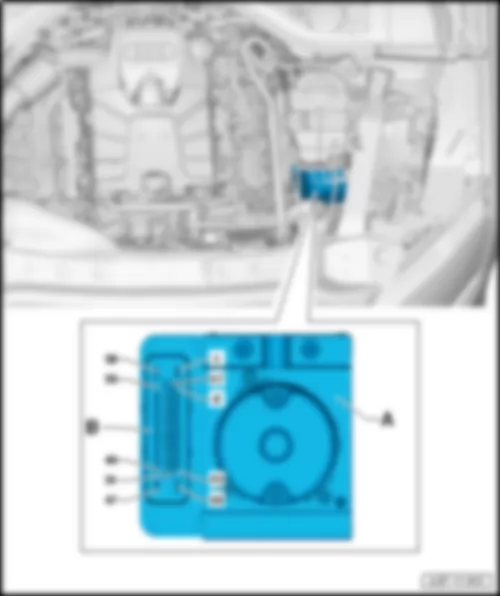
AUDI A7 2014 Fitting location, ABS control unit J104 Fitting location, ABS control unit -J104- |
| In left of engine compartment. | | ABS control unit -J104- , 47-pin | | | | | A - | ABS control unit -J104- | | 1 - | ABS control unit -J104- | | A - | 38-pin connector -T38a- , black |
AUDI A7 2014 Fitting location, adaptive cruise control unit J428 | A - | Adaptive cruise control unit -J428- | | B - | 8-pin connector -T8k- , black |
AUDI A7 2014 Fitting location, control unit 2 for adaptive cruise control J850 | A - | Control unit 2 for adaptive cruise control -J850- | | B - | 8-pin connector -T8l- , black |
AUDI A7 2014 Fitting location, sliding sunroof adjustment control unit J245 | A - | 10-pin connector -T10b- , black | | B - | Sliding sunroof adjustment control unit -J245- | | q | with sliding sunroof motor -V1- |
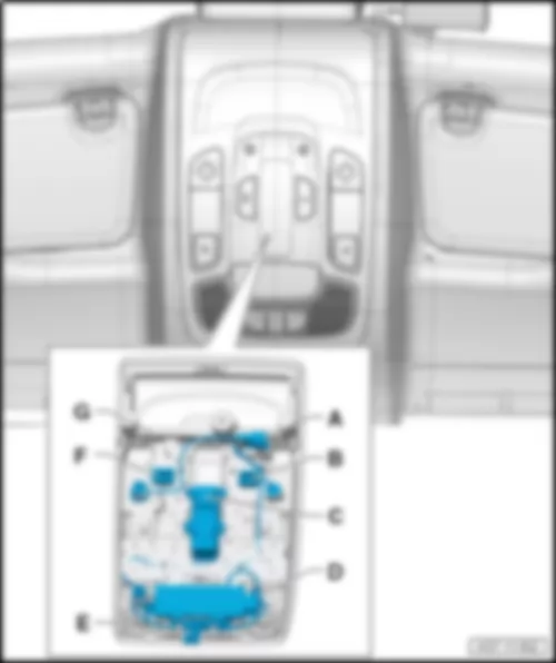
AUDI A7 2014 Fitting location, roof electronics control unit J528 Fitting location, roof electronics control unit -J528- |
| In front interior light -W1- | | | | | B - | 10-pin connector -T10ab- , red | | D - | 4-pin connector -T4v- , black, anti-theft alarm sensor -G578- | | F - | 10-pin connector -T10ac- , black, rear left reading light button -E454- , rear right reading light button -E455- | | G - | Roof electronics control unit -J528- | | q | with front interior light -W1- , front left reading light button -E633- , front right reading light button -E634- , front button for rear reading light -E635- , front left reading light -W65- , front right reading light -W66- , front interior light button -E326- |
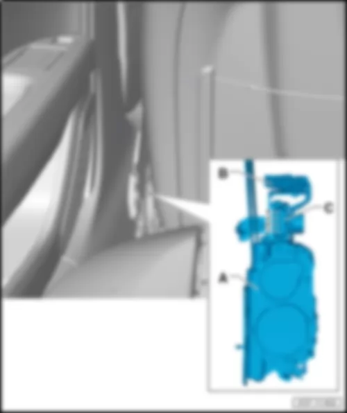
AUDI A7 2014 Fitting location, control unit for front left belt tensioner -J854- /control unit for front right belt tensioner -J855- |
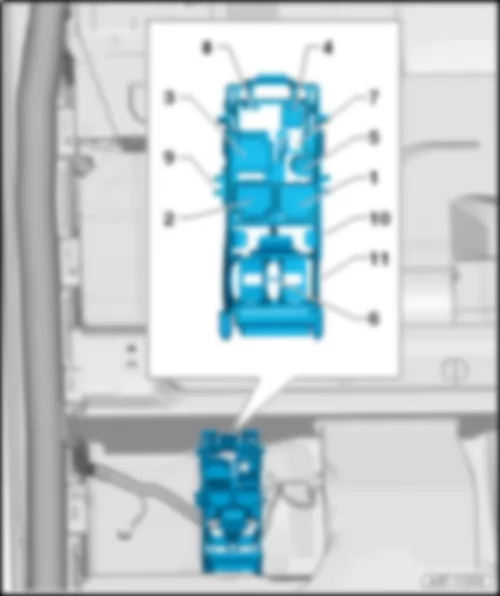
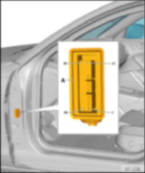
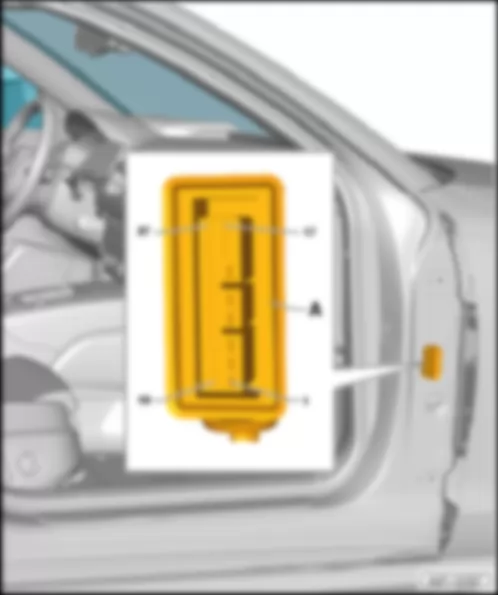
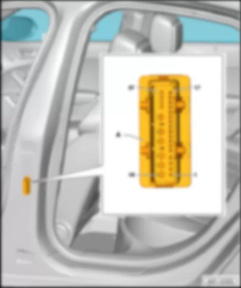
| In lower part of B-pillars. | | | | | A - | Control unit for front left belt tensioner -J854- /control unit for front right belt tensioner -J855- | | q | with driver seat belt tensioner igniter 1 -N153- , front passenger seat belt tensioner igniter 1 -N154- , driver side belt force limiter -G551- , front passenger side belt force limiter -G552- | | B - | 5-pin connector -T5h- , right, black, airbag control unit -J234- | | C - | 4-pin connector -T4ac- , right, black |
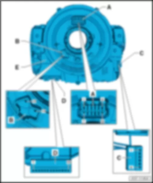
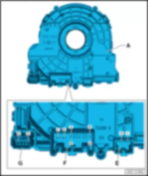
AUDI A7 2014 Fitting location, steering column electronics control unit J527 Fitting location, steering column electronics control unit -J527- |
| On steering column, at steering column switch. | | | | | B - | 2-pin connector -T2fk- , black, airbag coil connector and return ring with slip ring -F138- , heated steering wheel -Z36- | | D - | 13-pin connector -T13b- , black, turn signal switch -E2- , headlight flasher switch -E5- , cruise control system switch -E45- | | E - | Steering column electronics control unit -J527- | | q | with turn signal switch -E2- , headlight flasher switch -E5- , intermittent wiper switch -E22- , cruise control system switch -E45- , coil connector -F350- , steering angle sender -G85- , lane departure warning button -E517- , airbag coil connector and return ring with slip ring -F138- |
| A - | Steering column electronics control unit -J527- | | F - | 16-pin connector -T16e- , black |
AUDI A7 2014 Fitting location, power steering control unit J500 Fitting location, power steering control unit -J500- |
| | | | A - | Power steering control unit -J500- | | q | with electromechanical power steering motor -V187- , steering moment sender -G269- | | C - | 6-pin connector -T6ak- , black |
AUDI A7 2014 Fitting location, auxiliary heater control unit J364 Fitting location, auxiliary heater control unit -J364- |
| At front of right longitudinal member. | | | | | A - | Auxiliary heater control unit -J364- | | q | with temperature sensor 2 for supplementary and auxiliary heating -G587- , flame monitor -G64- , temperature sensor -G18- , glow plug for heater -Q9- , combustion air blower -V6- , fuel pre-heating heater element -Z66- | | C - | 6-pin connector -T6k- , black |
| Connector assignment, auxiliary heater control unit -J364- | | | | | -T6k- (C) | Designation | | 1 | Dash panel insert CAN bus high
B708 connection 1 (dash panel insert CAN bus high) in main wiring harness
Data bus diagnostic interface -J533- | | 2 | Dash panel insert CAN bus low
B709 connection 1 (dash panel insert CAN bus low) in main wiring harness
Data bus diagnostic interface -J533- | | 3 | Heater coolant shut-off valve -N279- | | 4 | Metering pump -V54- | | 5 | Terminal 31, to 380 earth connection 15 in main wiring harness
43 earth point at bottom of right A-pillar | | 6 | Remote control receiver for auxiliary heater -R64- |
| -T2az- (B) | Designation | | 1 | Terminal 30, from fuse holder F -SF- | | 2 | Terminal 31, to 379 earth connection 14 in main wiring harness
43 earth point at bottom of right A-pillar |
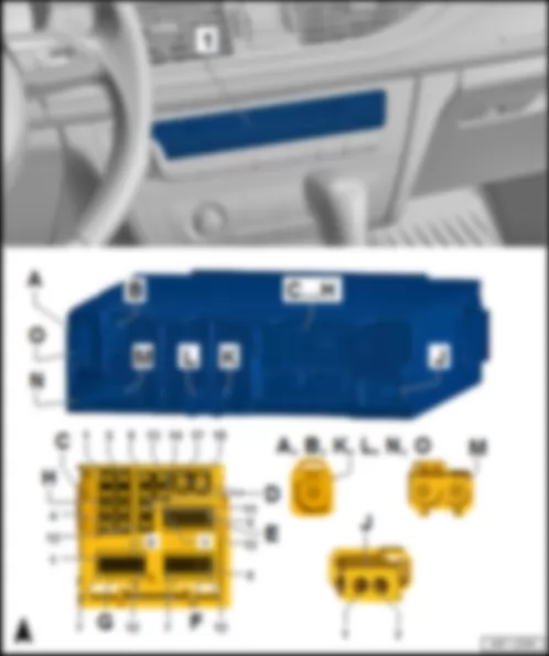
AUDI A7 2014 Fitting location, Climatronic control unit J255 | C - | 16-pin connector -T16f- , brown | | D - | 16-pin connector -T16p- , black |
AUDI A7 2014 Fitting location, control unit for electrically adjustable steering column J866 | A - | 18-pin connector -T18d- , black | | B - | Control unit for electrically adjustable steering column -J866- |
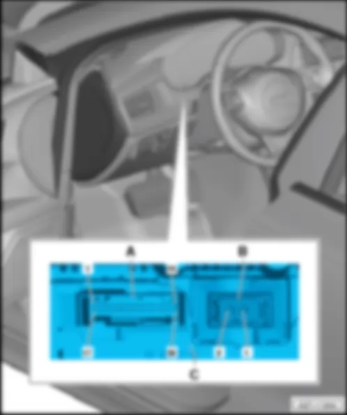
AUDI A7 2014 Fitting location, control unit in dash panel insert J285 Fitting location, control unit in dash panel insert -J285- |
| In driver side dash panel. | | | | | B - | 2-pin connector -T2bm- , MOST bus, black | | C - | Control unit in dash panel insert -J285- | | q | with fuel gauge -G1- , display in dash panel insert -Y24- , main beam warning lamp -K1- , ABS warning lamp -K47- , warning lamp for left turn signal -K261- , airbag warning lamp -K75- , diesel electronics warning lamp -K104- , engine electronics warning lamp -K149- , warning lamp for right turn signal -K262- |
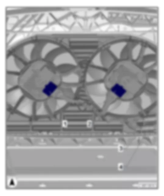
AUDI A7 2014 Fitting location, radiator fan control unit -J293- /radiator fan control unit 2 -J671- |
| | | | 1 - | Radiator fan control unit -J293- | | 2 - | Radiator fan control unit 2 -J671- | | 4 - | 4-pin connector -T4bf- , black |
AUDI A7 2014 Fitting location of control units on interior mirror | 1 - | Camera control unit -J852- | | q | Fitting location and connectors | | 2 - | Automatic anti-dazzle interior mirror -Y7- | | q | with light sensor -G399- , rain and light sensor -G397- | | 3 - | Humidity sender -G355- | | 4 - | Main beam assist control unit -J844- |
| Fitting location, camera control unit -J852- | | A - | Camera control unit -J852- | | C - | 12-pin connector -T12a- , black |
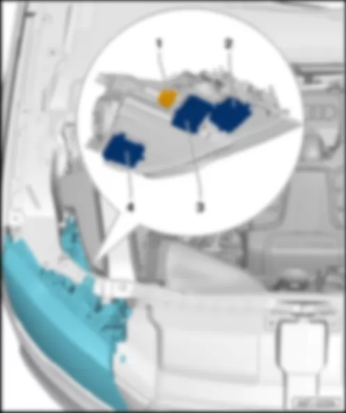
AUDI A7 2014 Fitting location, left gas discharge bulb control unit -J343- /right gas discharge bulb control unit -J344- |
Note: | Figure shows right headlight. | | | | | 14-pin connector -T14c- /14-pin connector -T14d- , black | | 2 - | Control unit for left daytime running light and side light -J860- /control unit for right daytime running light and side light -J861- | | 3 - | Output module for left headlight -J667- /output module for right headlight -J668- | | 4 - | Left gas discharge bulb control unit -J343- /right gas discharge bulb control unit -J344- |
| in headlight: -L176- , -M5- , -M51- , -V48- , -L13- , -G474- , -V318- , -G325- , -V294- , -L177- , -M7- , -M52- , -V49- , -L14- , -G475- , -V319- , -G327- , -V295- |
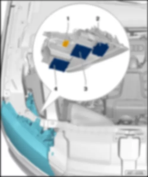
AUDI A7 2014 Fitting location, output module 1 for left LED headlight -A31- /output module 1 for right LED headlight -A27- |
Note: | Figure shows right headlight. | | | | | 1 - | 14-pin connector -T14c- /14-pin connector -T14d- , black | | 2 - | Output module 3 for left LED headlight -A33- /output module 3 for right LED headlight -A29- | | 3 - | Output module 2 for left LED headlight -A32- /output module 2 for right LED headlight -A28- | | 4 - | Output module 1 for left LED headlight -A31- /output module 1 for right LED headlight -A27- |
| in headlight: -V407- , -V48- , -V463- , -V294- , -G702- , -M29- , -L207- , -G703- , -M30- , -M51- , -M5- , -L176- , -V408- , -V464- , -V295- , -V49- , -G704- , -G705- , -L177- , -L208- , -M7- , -M31- , -M32- , -M52- |
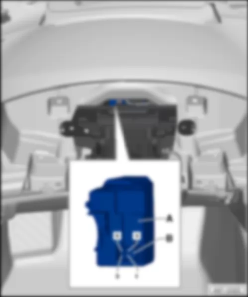
AUDI A7 2014 Fitting location, control unit for electronic steering column lock J764 Fitting location, control unit for electronic steering column lock -J764- |
| | | | A - | Control unit for electronic steering column lock -J764- | | B - | 6-pin connector -T6- , black |
AUDI A7 2014 Fitting location, fresh air blower control unit J126 | 1 - | Fresh air blower control unit -J126- | | q | with fresh air blower -V2- | | A - | 4-pin connector -T4cb- , black |
| Connector assignment, fresh air blower control unit -J126- | | | | | -T4cb- (A) | Designation | | 1 | Terminal 31, to 81 earth connection 1 in dash panel wiring harness
45 earth point behind centre of dash panel | | 2 | | | 3 | Terminal 30, from fuse holder C -SC- | | 4 | Climatronic control unit -J255- |
AUDI A7 2014 | 1 - | Active steering motor -V477- | | 2 - | Active steering safety lock actuator -F437- | | B - | 4-pin connector -T4ag- , black | | C - | 2-pin connector -T2bk- , black |
| Connector assignment Active steering motor -V477- /Active steering safety lock actuator -F437- | | | | | -T6m- (A) | Designation | | -T6m- (A) | Designation | | 1 | Active steering control unit -J792- | | 4 | Active steering control unit -J792- | | 2 | Active steering control unit -J792- | | 5 | Active steering control unit -J792- | | 3 | Active steering control unit -J792- | | 6 | Active steering control unit -J792- |
| -T4ag- (B) | Designation | | -T2bk- (C) | Designation | | 1 | Active steering control unit -J792- | | 1 | Active steering control unit -J792- | | 2 | Active steering control unit -J792- | | 2 | Active steering control unit -J792- | | 3 | Active steering control unit -J792- | | | | | 4 | Terminal 31, shield earth | | | |
AUDI A7 2014 Fitting location, control unit for wiper motor J400 | 1 - | Wiper motor control unit -J400- | | q | with windscreen wiper motor -V- | | A - | 4-pin connector -T4t- , black | | q | Left and right-hand models have different assignments |
| Connector assignment, wiper motor control unit -J400- , left-hand and right-hand drive | | | | | -T4t- (A) | Designation | | 1 (LHD) | Terminal 30, from fuse holder B -SB- | | 1 (RHD) | LIN bus
B698 connection 3 (LIN bus) in main wiring harness
Onboard supply control unit -J519- | | 2 (LHD) | Terminal 31, to 369 earth connection 4 in main wiring harness
44 earth point on lower left of A-pillar | | 2 (RHD) | | | 3 (LHD) | | | 3 (RHD) | Terminal 31, to 369 earth connection 4 in main wiring harness
44 earth point on lower left of A-pillar | | 4 (LHD) | LIN bus
B698 connection 3 (LIN bus) in main wiring harness
Onboard supply control unit -J519- | | 4 (RHD) | Terminal 30, from fuse holder B -SB- |
AUDI A7 2014 Fitting location, control unit for structure-borne sound J869 | 1 - | Control unit for structure-borne sound -J869- | | A - | 6-pin connector -T6bw- , black |
| Connector assignment, control unit for structure-borne sound -J869- | | | | | -T6bw- (A) | Designation | | 1 | Actuator for structure-borne sound -R214- | | 2 | Actuator for structure-borne sound -R214- | | 3 | Terminal 15, from B279 positive connection 3 (15a) in main wiring harness
Fuse holder B -SB- | | 4 | Terminal 31, to 366 earth connection 1 in main wiring harness
44 earth point on lower left of A-pillar | | 5 | Powertrain CAN bus, low
B390 connection 1 (powertrain CAN bus, low) in main wiring harness | | 6 | Powertrain CAN bus, high
B383 connection 1 (powertrain CAN bus, high) in main wiring harness |
AUDI A7 2014 Fitting location, power unit mounting control unit J931 | A - | Power unit mounting control unit -J931- | | B - | 28-pin connector -T28- , black |
| Connector assignment, power unit mounting control unit -J931- | | | | | -T28- (B) | Designation | | -T28- (B) | Designation | | -T28- (B) | Designation | | -T28- (B) | Designation | | 53 | Terminal 30, from B321 positive connection 7 (30a) in main wiring harness
Fuse holder F -SF- | | 60 | | | 67 | Terminal 30, from B321 positive connection 7 (30a) in main wiring harness
Fuse holder F -SF- | | 74 | Power unit mounting actuator 1 -N513- | | 54 | Terminal 15, from B281 positive connection 5 (15a) in main wiring harness
Fuse holder B -SB- | | 61 | | | 68 | Power unit mounting actuator 1 -N513- | | 75 | Power unit mounting actuator 2 -N514- | | 55 | | | 62 | | | 69 | Power unit mounting actuator 2 -N514- | | 76 | | | 56 | CAN bus extended low
B109 connection 1 (CAN bus extended low) in main wiring harness | | 63 | Earth
Power unit mounting sender 1 -G748- | | 70 | 5 V output, to D129 connection 27 in engine compartment wiring harness
Power unit mounting sender 2 -G749-
Power unit mounting sender 1 -G748- | | 77 | | | 57 | CAN bus extended high
B108 connection 1 (CAN bus extended high) in main wiring harness | | 64 | | | 71 | Earth
Power unit mounting sender 2 -G749- | | 78 | Signal
Power unit mounting sender 1 -G748- | | 58 | | | 65 | | | 72 | | | 79 | Signal
Power unit mounting sender 2 -G749- | | 59 | Speed signal from
D130 connection 28 in engine compartment wiring harness
Engine control unit -J623-
to digital sound package control unit -J525- | | 66 | Terminal 31, to 398 earth connection 33 in main wiring harness
379 earth connection 14 in main wiring harness
43 earth point at bottom of right A-pillar | | 73 | | | 80 | Terminal 31, to 398 earth connection 33 in main wiring harness
379 earth connection 14 in main wiring harness
43 earth point at bottom of right A-pillar |
AUDI A7 2014 Fitting location, catalytic converter heater control unit 1 J1021 | 1 - | Catalytic converter heater control unit 1 -J1021- | | B - | 4-pin connector -T4gk- , black | | C - | 2-pin connector -T2qb- , brown |
| Connector assignment, catalytic converter heater control unit 1 -J1021- | | | | | -T4gk- (B) | Designation | | -T4gk- (B) | Designation | | 1 | Powertrain CAN bus, high
E123 connection 1 (powertrain CAN bus, high) in engine wiring harness | | 3 | Powertrain CAN bus, low
E123 connection 1 (powertrain CAN bus, low) in engine wiring harness | | 2 | Terminal 31, to 714 earth point on right on engine | | 4 | Terminal 87, from D181 connection 2 (87a) in engine compartment wiring harness |
| -T2qc- (A) | Designation | | -T2qb- (C) | Designation | | 1 | Catalytic converter heater 1 -Z119- | | 1 | Terminal 30 wiring junction -TV2-
Catalytic converter heater fuse -S351- | | 2 | Catalytic converter heater 2 -Z120- | | 2 | Terminal 30 wiring junction -TV2-
Catalytic converter heater fuse 2 -S354- |
AUDI A7 2014 Fitting location, control unit 1 for information electronics -J794- , MMI Navigation plus, 7UG, from model year 2015 |
| At centre of dash panel -1- . | | | | | 1 - | Control unit 1 for information electronics -J794- | | B - | 2-pin connector -T2nf- , aerial connection, DAB, black, aerial amplifier 3 -R112- , digital radio aerial -R183- | | B - | 2-pin connector -T2nf- , aerial connection, SAT, brown,satellite aerial -R170- , USA only | | E - | 12-pin connector -T12d- , grey | | G - | 12-pin connector -T12g- , blue | | J - | 2-pin connector -T2aw- , MOST bus, black | | L - | 5-pin connector -T5bq- , brown, USB connection holder -R193- | | N - | 2-pin connector -T2au- , aerial connection, GPS, blue, roof aerial -R216- , GPS aerial -R50- | | O - | 2-pin connector -T2at- , aerial connection, LTE, Bordeaux, LTE aerial 2 -R306- |
| Connector assignment, control unit 1 for information electronics -J794- | | | | | -T8f- (D) | Designation | | -T8e- (H) | Designation | | 9 | Subwoofer -R211- | | 1 | Rear right treble loudspeaker -R16-
Rear right mid-range and bass loudspeaker -R160- | | 10 | Centre loudspeaker -R208- | | 2 | Front right treble loudspeaker -R22-
Front right mid-range and bass loudspeaker -R102- | | 11 | | | 3 | Front left treble loudspeaker -R20-
Front left mid-range and bass loudspeaker -R101- | | 12 | | | 4 | Rear left treble loudspeaker -R14-
Rear left mid-range and bass loudspeaker -R159- | | 13 | Subwoofer -R211- | | 5 | Rear right treble loudspeaker -R16-
Rear right mid-range and bass loudspeaker -R160- | | 14 | Centre loudspeaker -R208- | | 6 | Front right treble loudspeaker -R22-
Front right mid-range and bass loudspeaker -R102- | | 17 | Terminal 31, to 372 earth connection 7 in main wiring harness
687 earth point 1 on centre tunnel | | 7 | Front left treble loudspeaker -R20-
Front left mid-range and bass loudspeaker -R101- | | 18 | Terminal 30, from fuse holder F -SF- | | 8 | Rear left treble loudspeaker -R14-
Rear left mid-range and bass loudspeaker -R159- |
| -T12d- (E) | Designation | | -T12f- (F) | Designation | | 1 | Display unit for front information display and operating unit control unit -J685- | | 1 | Connection for external audio sources -R199- | | 2 | Multimedia system operating unit -E380- | | 2 | Connection for external audio sources -R199- | | 3 | Ring break diagnostic cable
B444 connection 1 (diagnosis) in main wiring harness | | 3 | Connection for external audio sources -R199- | | 4 | Multimedia system operating unit -E380- | | 4 | | | 5 | Telephone bracket -R126-
B478 connection 14 in main wiring harness | | 5 | | | 6 | Dash panel insert CAN bus high
B708 connection 1 (dash panel insert CAN bus high) in main wiring harness | | 6 | | | 7 | Display unit for front information display and operating unit control unit -J685- | | 7 | Connection for external audio sources -R199- | | 8 | Multimedia system operating unit -E380- | | 8 | Screen earth | | 9 | Multimedia system operating unit -E380- | | 9 | | | 10 | Multimedia system operating unit -E380- | | 10 | | | 11 | Telephone bracket -R126- | | 11 | | | 12 | Dash panel insert CAN bus low
B709 connection 1 (dash panel insert CAN bus low) in main wiring harness | | 12 | |
| -T12g- (G) | Designation | | -T12g- (G) | Designation | | 1 | Left front microphone -R140- | | 7 | Left front microphone -R140- | | 2 | Front right microphone -R141- | | 8 | Front right microphone -R141- | | 3 | | | 9 | | | 4 | | | 10 | | | 5 | | | 11 | | | 6 | Reversing camera system control unit -J772- | | 12 | Reversing camera system control unit -J772- |
AUDI A7 2014 Fitting location, seat and steering column adjustment control unit with memory J136 | 1 - | Seat and steering column adjustment control unit with memory -J136- | | B - | 32-pin connector -T32m- , grey | | C - | 16-pin connector -T16q- , black |
| Connector assignment, seat and steering column adjustment control unit with memory -J136- | | | | | -T12x- (A) | Designation | | -T12x- (A) | Designation | | 1 | Driver seat backrest adjustment motor -V45- | | 7 | Driver seat rake adjustment motor -V243- | | 2 | Driver seat depth adjustment motor -V256- | | 8 | Driver seat height adjustment motor -V245- | | 3 | Driver seat height adjustment motor -V245- | | 9 | Driver seat longitudinal adjustment motor -V28- | | 4 | Driver seat depth adjustment motor -V256- | | 10 | Driver seat rake adjustment motor -V243- | | 5 | Driver seat longitudinal adjustment motor -V28- | | 11 | Terminal 30, from driver seat adjustment thermal fuse 1 -S44- | | 6 | Driver seat backrest adjustment motor -V45- | | 12 | Terminal 31, to 95 earth connection 1 in wiring harness
371 earth connection 6 in main wiring harness
34 earth point under driver seat |
| -T32m- - (B) | Designation | | -T32m- (B) | Designation | | 1 | | | 17 | | | 2 | | | 18 | | | 3 | Driver door control unit -J386- | | 19 | | | 4 | | | 20 | | | 5 | Driver seat massage function button -E670- | | 21 | | | 6 | Seat longitudinal adjustment button -E418-
Switch module 2 for driver seat -E667- | | 22 | Driver seat backrest adjustment switch -E96-
Switch module for driver seat -E663- | | 7 | Seat height adjustment button -E424-
Switch module 2 for driver seat -E667- | | 23 | Driver seat height adjustment switch -E364-
Switch module for driver seat -E663- | | 8 | | | 24 | Driver seat rake adjustment switch -E222-
Switch module for driver seat -E663- | | 9 | | | 25 | Driver seat longitudinal adjustment switch -E363-
Switch module for driver seat -E663- | | 10 | 413 Earth connection 4 in seat adjustment wiring harness
Switch module 2 for driver seat -E667-
Driver seat massage function button -E670-
Switch module for driver seat -E663- | | 26 | | | 11 | | | 27 | | | 12 | | | 28 | Backrest adjustment button -E425-
Switch module 2 for driver seat -E667- | | 13 | | | 29 | | | 14 | | | 30 | | | 15 | Convenience CAN bus, low
M28 connection (convenience CAN bus, low) in driver seat adjustment wiring harness | | 31 | | | 16 | Convenience CAN bus, high
M27 connection (convenience CAN bus, high) in driver seat adjustment wiring harness | | 32 | |
| -T16q- (C) | Designation | | -T16q- (C) | Designation | | 1 | Driver seat cushion lateral support heater -Z31- | | 9 | M43 connection 3 in driver seat wiring harness
Driver seat backrest fan -V388-
Driver seat backrest fan 2 -V417- | | 2 | Heated driver seat -Z6- | | 10 | M44 connection 4 in driver seat wiring harness
Driver seat backrest fan -V388-
Driver seat backrest fan 2 -V417- | | 3 | M42 connection 2 in driver seat wiring harness
Driver seat cushion fan -V390-
Driver seat cushion fan 2 -V419- | | 11 | | | 4 | | | 12 | 136 earth connection 2 in seat heating wiring harness | | 5 | | | 13 | | | 6 | | | 14 | Front left seat temperature sender -G344- | | 7 | Front left seat temperature sender -G344- | | 15 | | | 8 | M41 connection 1 in driver seat wiring harness
Driver seat cushion fan -V390-
Driver seat cushion fan 2 -V419- | | 26 | |
AUDI A7 2014 Fitting location, seat occupied recognition control unit J706 Fitting location, seat occupied recognition control unit -J706- |
| | | | 1 - | Seat occupied recognition control unit -J706- | | A - | 3-pin connector -T3- , black | | B - | Connection, seat occupied recognition control unit -G452- |
| Connector assignment, seat occupied recognition control unit -J706- | | | | | -T3- (A) | Designation | | 1 | Terminal 30, from B282 positive connection 6 (15a) in main wiring harness
Fuse holder B | | 2 | Airbag control unit -J234- | | 3 | Terminal 31, to 312 earth connection 2 in airbag wiring harness
475 earth connection (airbag) in main wiring harness
Airbag control unit -J234- |
AUDI A7 2014 Fitting location, Tyre Pressure Monitoring System control unit J502 | 1 - | Tyre Pressure Monitoring System control unit -J502- | | A - | 12-pin connector -T12ao- , black |
| Connector assignment, Tyre Pressure Monitoring System control unit -J502- | | | | | -T12ao- (A) | Designation | | -T12ao- (A) | Designation | | 1 | | | 7 | Dash panel insert CAN bus, high
Wiring junction for dash panel insert CAN bus, high -TV36- | | 2 | | | 8 | Dash panel insert CAN bus, low
Wiring junction for dash panel insert CAN bus, low -TV40- | | 3 | B605 connection 1 in interior wiring harness to
Tyre Pressure Monitoring System aerials | | 9 | Front left Tyre Pressure Monitoring System aerial -R59- | | 4 | Front right Tyre Pressure Monitoring System aerial -R60- | | 10 | Rear left Tyre Pressure Monitoring System aerial -R61- | | 5 | Rear right Tyre Pressure Monitoring System aerial -R62- | | 11 | B606 connection 2 in interior wiring harness to
Tyre Pressure Monitoring System aerials | | 6 | Terminal 30, from fuse holder F -SF- | | 12 | Terminal 31, to 380 earth connection 15 in main wiring harness
43 earth point at bottom of right A-pillar |
|
| |
| |
| |
| |
| |
| |
| |
| |
| |
| |
| |
| |
| |
| | |
| |
| | | | | | | | | | | | | | | | | | | |
| |
| | | |

