AUTOMOTIVE ELECTRICIANS PORTAL

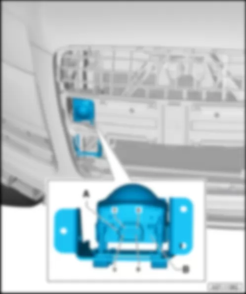
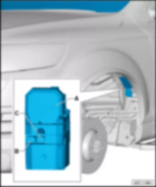
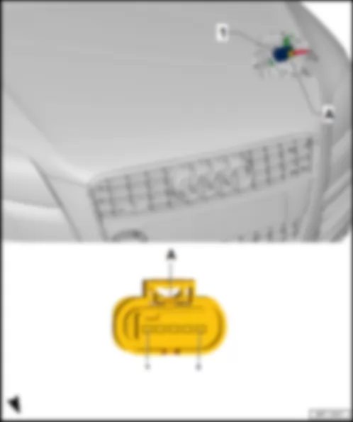
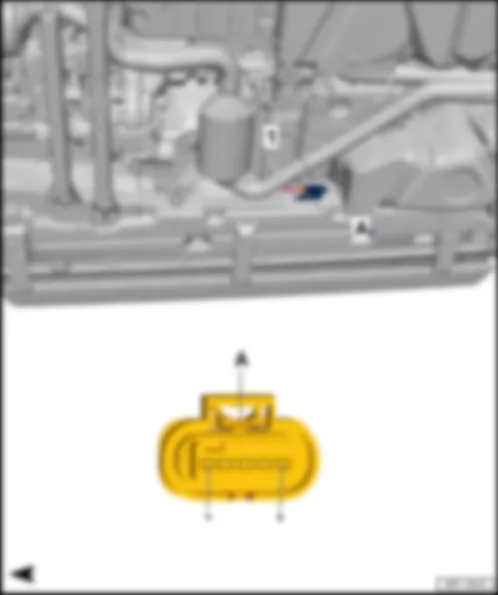
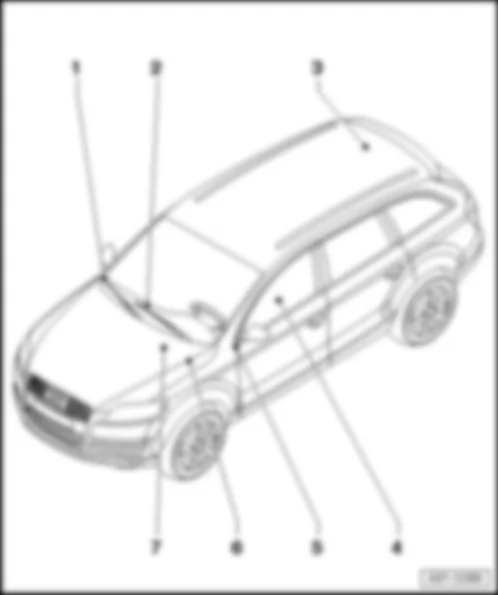
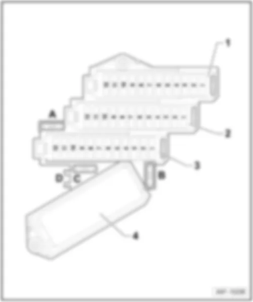
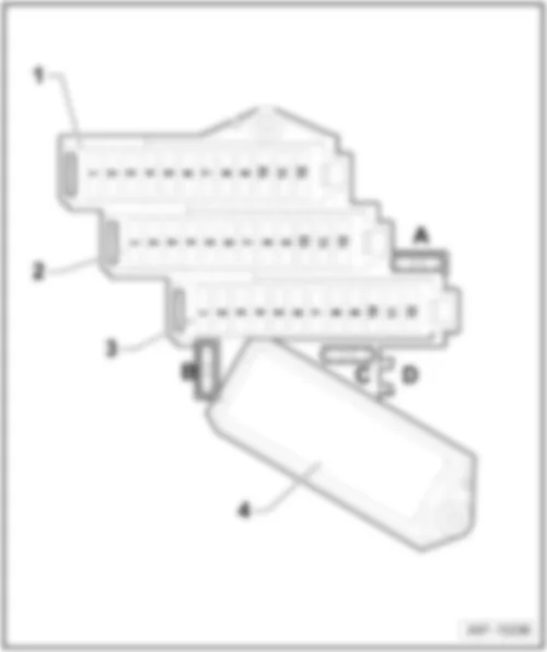
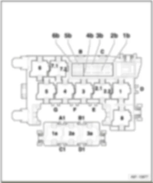
AUDI Q7 2011 — Reversing camera system . Wiring diagrams, Pin Connector, Location

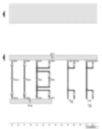
Wiring Diagram AUDI Q7 2011 - Reversing camera system control unit - fuses


Wiring Diagram  AUDI Q7 2011 - Reversing camera system control unit - fuses https://portal-diagnostov.com/license.html
https://portal-diagnostov.com/license.html Automotive Electricians Portal FZCO Automotive Electricians Portal FZCO
Download PDF file
J772Reversing camera system control unit
SC2Fuse 2 on fuse holder C
SC3Fuse 3 on fuse holder C
SD2Fuse 2 on fuse holder D
SD3Fuse 3 on fuse holder D
SD5Fuse 5 on fuse holder D
SF4Fuse 4 on fuse holder F
SF6Fuse 6 on fuse holder F
SF8Fuse 8 on fuse holder F
SF11Fuse 11 on fuse holder F
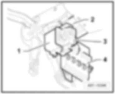
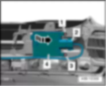
T46b46-pin connector, black, CAN disconnector right
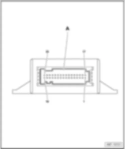
T5454-pin connector, black, on reversing camera system control unit
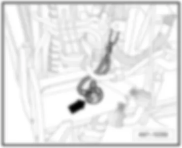
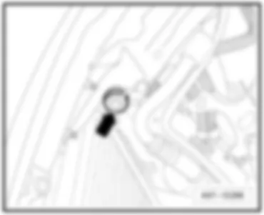
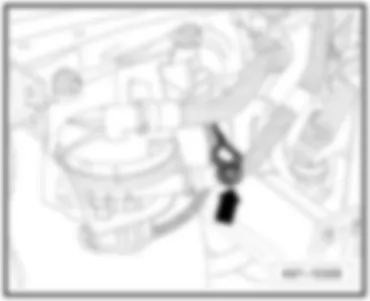
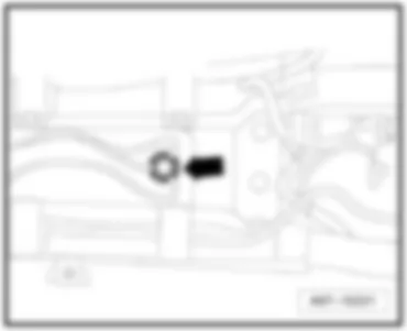
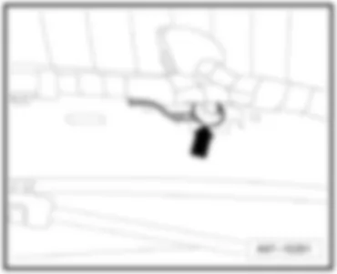
   51 Earth point, on right in luggage compartment
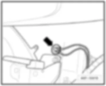
   389 Earth connection 24, in main wiring harness
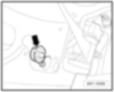
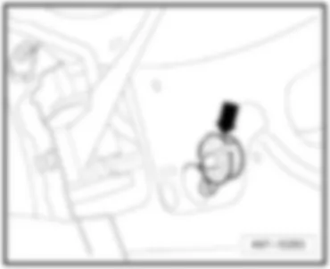
   390 Earth connection 25, in main wiring harness
   B397 Connection 1 (convenience CAN bus, high), in main wiring harness
   B406 Connection 1 (convenience CAN bus, low), in main wiring harness
CAN bus (data wire)
*Relay and fuse carrier under driver seat
#up to May 2009
##from June 2009
###from June 2010

Wiring Diagram AUDI Q7 2011 - Reversing camera system control unit - reversing camera


Wiring Diagram  AUDI Q7 2011 - Reversing camera system control unit - reversing camera https://portal-diagnostov.com/license.html
https://portal-diagnostov.com/license.html Automotive Electricians Portal FZCO Automotive Electricians Portal FZCO
Получить доступ ко всем электросхемам автомобиляDownload PDF file
J523Front information display and operating unit control unit
J772Reversing camera system control unit
J794Control unit for information electronics 1
R78TV tuner
R189Reversing camera
T2ah2-pin connector, grey, on reversing camera system control unit
T2ai2-pin connector, brown, on reversing camera system control unit
T2ak2-pin connector, green, on reversing camera system control unit
T2al2-pin connector, brown, coupling rear lid
T2am2-pin connector, black, on reversing camera
T2an2-pin connector, grey, on reversing camera
T10s10-pin connector, pink, coupling rear lid
T5454-pin connector, black, on reversing camera system control unit
*up to May 2009
**from June 2009


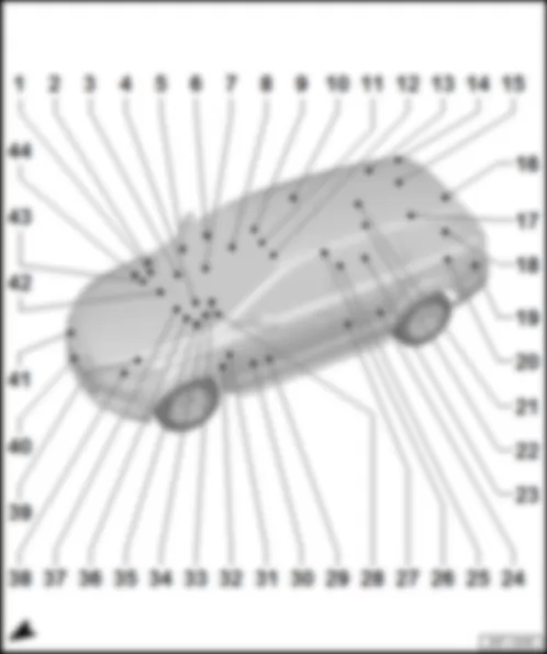
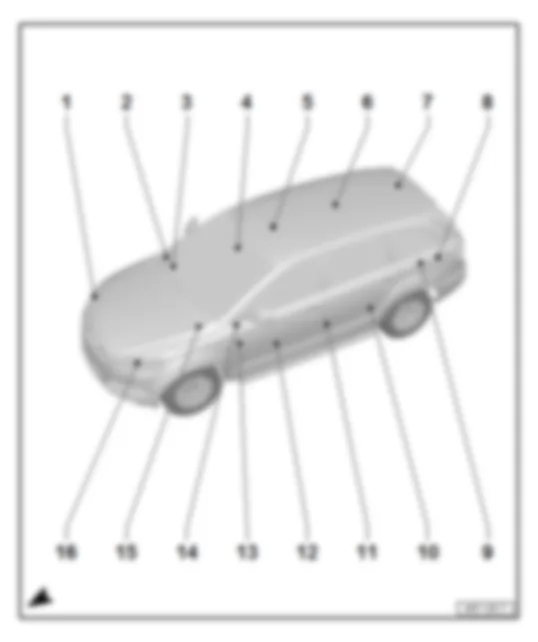
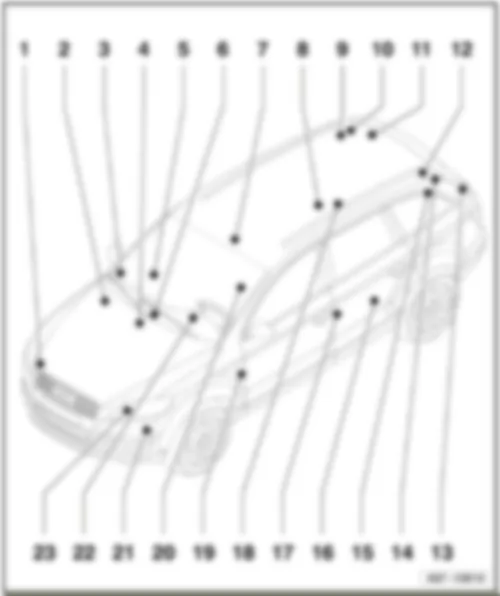
AUDI Q7 2011 Overview of control units

Overview of control units
AUDI Q7 2011 Overview of control units https://portal-diagnostov.com/license.html
https://portal-diagnostov.com/license.html Automotive Electricians Portal FZCO Automotive Electricians Portal FZCO
Получить доступ ко всем электросхемам автомобиляDownload PDF file
1 -  Control unit for structure-borne sound -J869-
q   Fitting location and connectors → chapter
2 -  ABS control unit -J104-
q   Fitting location and connectors → chapter
3 -  Voltage stabiliser -J532-
q   Fitting location and connectors → chapter
3 -  Fresh air blower control unit -J126-
q   Fitting location and connector → chapter
4 -  Entry and start authorisation control unit -J518-
q   Fitting location and connectors → chapter
5 -  Front passenger door control unit -J387-
q   Fitting location and connectors → chapter
6 -  Onboard supply control unit 2 -J520-
q   Fitting location and connectors → chapter
6 -  Automatic gearbox control unit -J217-, gearbox 0AT
q   for models with 0AT automatic gearbox only
q   Fitting location and connectors → chapter
6 -  Telephone transmitter and receiver unit -R36-, up to May 2009
q   Fitting location and connectors → chapter
7 -  Front passenger seat adjustment with memory control unit -J521-
q   Fitting location and connectors → chapter
8 -  Lane departure warning control unit -J759-
q   Fitting location and connectors → chapter
9 -  Sliding sunroof adjustment control unit -J245-
q   Component: -V1-
q   Fitting location and connectors → chapter
10 -  Rear right door control unit -J389-
q   Fitting location and connectors → chapter
11 -  Front interior light
q   Components: -W16-, -W17-, -W19-, -E326-, -E457-, -W13-, -E458-, -E139-, -R164-
q   Fitting location and connectors → chapter
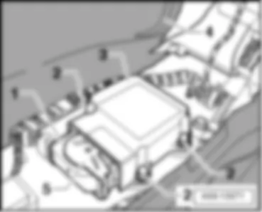
12 -  Airbag control unit -J234-
q   Fitting location and connectors → chapter
13 -  Rear sliding sunroof control unit -J392-
q   Component: -V146-
q   Fitting location and connectors → chapter
14 -  Rear lid control unit -J605-
q   Component: -V375-
q   Fitting location and connectors → chapter
15 -  Sunroof roller blind control unit -J394-
q   Component: -V260-
q   Fitting location and connectors → chapter
16 -  Rear lid control unit 2 -J756-
q   Component: -V376-
q   Fitting location and connectors → chapter
17 -  Lane change assist control unit -J769-
q   Fitting location and connectors → chapter
18 -  Power latching control unit -J657-
q   Components: -V120-, -F332-, -F333-
q   Fitting location and connectors → chapter
19 -  Lane change assist control unit 2 -J770-
q   Fitting location and connectors → chapter
20 -  Rear fresh air blower control unit -J391-
q   Fitting location and connectors → chapter
21 -  Radio -R-, MMI
q   Fitting location and connectors → chapter
21 -  Control unit for parking aid -J446-
q   Fitting location and connectors → chapter
21 -  Aerial reader unit for keyless entry system -J723-
q   Fitting location and connectors → chapter
21 -  Remote control receiver for auxiliary heater -R64-
q   Fitting location and connectors → chapter
21 -  TV tuner -R78-
q   Fitting location and connectors → chapter
21 -  Aerial amplifier for mobile telephone -R86-, not USA
q   Fitting location and connectors → chapter
21 -  Satellite radio -R146-, only USA, up to May 2009
q   Fitting location and connectors → chapter
21 -  Digital radio -R147-, up to May 2009
q   Fitting location and connectors → chapter
22 -  Reversing camera system control unit -J772-
q   Fitting location and connectors → chapter
22 -  Comfort system central control unit 2 -J773-
q   Fitting location and connectors → chapter
22 -  Comfort system central control unit -J393-
q   Fitting location and connectors → chapter
22 -  Adaptive suspension control unit -J197-
q   Fitting location and connectors → chapter
22 -  Navigation system with CD drive control unit -J401-, up to May 2009
q   Fitting location and connectors → chapter
22 -  Control unit for information electronics 1 -J794-, from June 2009
q   Fitting location and connectors → chapter
22 -  Trailer detector control unit -J345-
q   Fitting location and connectors → chapter
23 -  Control unit for reducing agent metering system -J880-
q   Fitting location and connectors → chapter
24 -  Fuel pump control unit -J538-
q   Fitting location and connectors → chapter
25 -  Control unit for NOx sensor 2 -J881-
q   Fitting location and connectors → chapter
26 -  Rear Climatronic operating and display unit -E265-
q   Components: -E128-, -E129-
q   Fitting location and connectors → chapter
27 -  Rear left door control unit -J388-
q   Fitting location and connectors → chapter
28 -  onboard supply control unit -J519-
q   Fitting location and connectors → chapter
29 -  Energy management control unit -J644-, up to May 2008
q   Fitting location and connectors → chapter
29 -  Battery monitor control unit -J367-, from June 2008
q   Fitting location → chapter
29 -  Control unit for seat adjustment and steering column adjustment with memory function -J136-
q   Fitting location and connectors → chapter
30 -  Driver door control unit -J386-
q   Fitting location and connectors → chapter
31 -  Control unit for headlight range control -J431-
q   Fitting location and connectors → chapter
31 -  Data bus diagnostic interface -J533-
q   Fitting location and connectors → chapter
31 -  Tyre pressure monitor control unit -J502-
q   Fitting location and connectors → chapter
32 -  Auxiliary heater control unit -J364-
q   Components: -S24-, -G18-, -Q8-, -V6-
q   Fitting location and connectors → chapter
33 -  16-pin connector -T16-, diagnosis connection
q   Fitting location and connectors → chapter
33 -  Steering column electronics control unit -J527-
q   Components: -E2-, -E5-, -F350-, -H-, -E22-, -G85-, -E45-, -E167-, -E517-, -J453-, -F138-, -Z36-, -N95-, -N250-
q   Fitting location and connectors → chapter
34 -  Control unit in dash panel insert -J285-
q   Components: -Y24-, -K32-, -K118-, -K3-, -G106-, -K28--Y8-, -K139-, -G1-
q   Fitting location and connectors → chapter
35 -  Entry​and​start​authorisation​switch -E415-
q   Fitting location and connectors → chapter
36 -  Wiper motor control unit -J400-
q   Component: -V-
q   Fitting location and connectors → chapter
37 -  Climatronic control unit -J255-
q   Components: -V42-, -G56-, -E94-, -E95-
q   Fitting location and connectors, comfort level air conditioning system → chapter
q   Fitting location and connectors, basic level air conditioning system → chapter
38 -  Left headlight starter for gas discharge light -J426-/right headlight starter for gas discharge light -J427-
q   Components: -J667-, -J668-, -J892-, -J893-, -J860-, -J861-, -L176-, -L177-, -L148-, -L149-, -V48-, -V49-, -V448-, -V449-, -G474-, -G475-, -L13-, -L14-
q   Fitting location and connectors → chapter
39 -  NOx sensor control unit -J583-
q   Fitting location and connectors → chapter
40 -  Radiator fan control unit -J293-/radiator fan control unit 2 -J671-
q   Components: -V7-, -V177-
q   Fitting location and connectors → chapter
41 -  Control unit for adaptive cruise control -J428-
q   Fitting location and connectors → chapter
42 -  Actuator for structure-borne sound -R214-
q   Fitting location and connectors → chapter
43 -  Engine control unit 2 -J624-
q   Fitting location and connectors → chapter
44 -  Engine control unit -J623-
q   Fitting location and connectors → chapter


AUDI Q7 2011 Onboard supply control unit 2 J520

Onboard supply control unit 2 -J520-
Fitting location
   
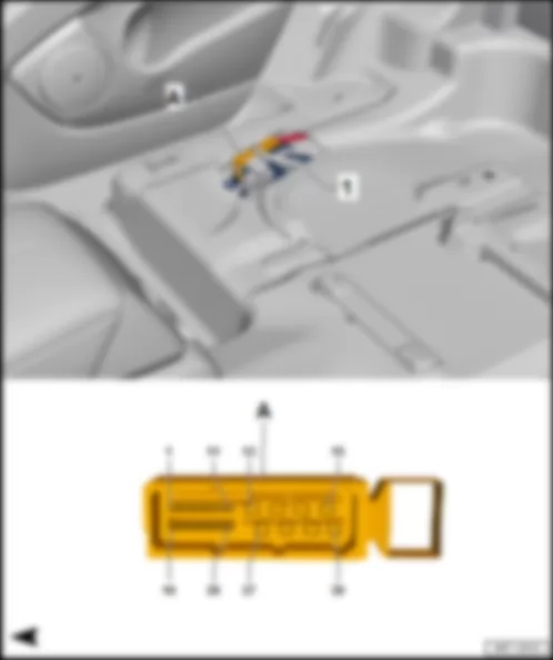
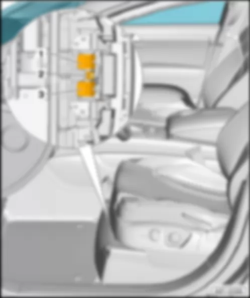
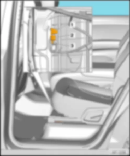
Under front passenger seat -1-.
 
AUDI Q7 2011 Onboard supply control unit 2 J520 https://portal-diagnostov.com/license.html
https://portal-diagnostov.com/license.html Automotive Electricians Portal FZCO Automotive Electricians Portal FZCO
Получить доступ ко всем электросхемам автомобиляDownload PDF file
Connector
AUDI Q7 2011 Onboard supply control unit 2 J520 https://portal-diagnostov.com/license.html
https://portal-diagnostov.com/license.html Automotive Electricians Portal FZCO Automotive Electricians Portal FZCO
Получить доступ ко всем электросхемам автомобиляDownload PDF file
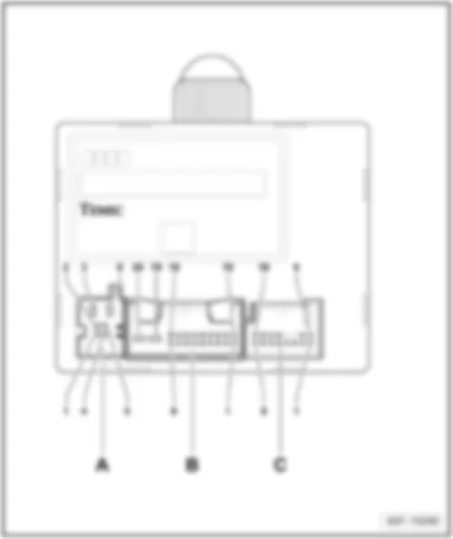
A -  Onboard supply control unit 2 -J520-
B -  40-pin connector -T40a-, black, on wiring harness

Back to overview → chapter.


AUDI Q7 2011 Automatic gearbox control unit J217

Automatic gearbox control unit -J217-
Fitting location
  Note
for models with automatic gearbox 0AT only
   
Under front passenger seat -2-.
 
AUDI Q7 2011 Automatic gearbox control unit J217 https://portal-diagnostov.com/license.html
https://portal-diagnostov.com/license.html Automotive Electricians Portal FZCO Automotive Electricians Portal FZCO
Получить доступ ко всем электросхемам автомобиляDownload PDF file
Connector
AUDI Q7 2011 Automatic gearbox control unit J217 https://portal-diagnostov.com/license.html
https://portal-diagnostov.com/license.html Automotive Electricians Portal FZCO Automotive Electricians Portal FZCO
Получить доступ ко всем электросхемам автомобиляDownload PDF file
A -  52-pin connector -T52-

Back to overview → chapter.


AUDI Q7 2011 Telephone transmitter and receiver unit R36 , up to May 2009

Telephone transmitter and receiver unit -R36-, up to May 2009
Fitting location
   
Under front passenger seat -3-.
 
AUDI Q7 2011 Telephone transmitter and receiver unit R36 , up to May 2009 https://portal-diagnostov.com/license.html
https://portal-diagnostov.com/license.html Automotive Electricians Portal FZCO Automotive Electricians Portal FZCO
Получить доступ ко всем электросхемам автомобиляDownload PDF file
Connectors:
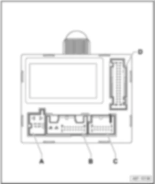
A -  Connection aerial for Bluetooth -R152-
B -  MOST bus
C -  54-pin connector -T54a-, black
Back to overview → chapter.


AUDI Q7 2011 Assignment diagnosis connection

Assignment diagnosis connection
Fitting location
 
AUDI Q7 2011 Assignment diagnosis connection https://portal-diagnostov.com/license.html
https://portal-diagnostov.com/license.html Automotive Electricians Portal FZCO Automotive Electricians Portal FZCO
Получить доступ ко всем электросхемам автомобиляDownload PDF file
In cover of lower dash panel, driver's side -1-.
 
AUDI Q7 2011 Assignment diagnosis connection https://portal-diagnostov.com/license.html
https://portal-diagnostov.com/license.html Automotive Electricians Portal FZCO Automotive Electricians Portal FZCO
Получить доступ ко всем электросхемам автомобиляDownload PDF file
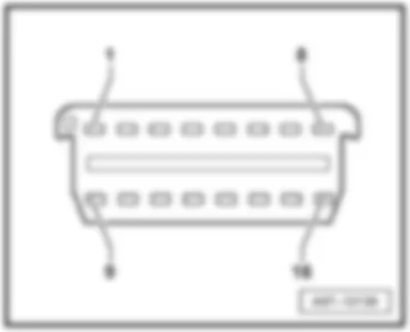
16-pin connector -T16-, black
Connector assignment
 
AUDI Q7 2011 Assignment diagnosis connection https://portal-diagnostov.com/license.html
https://portal-diagnostov.com/license.html Automotive Electricians Portal FZCO Automotive Electricians Portal FZCO
Получить доступ ко всем электросхемам автомобиляDownload PDF file
T16 Designation
1 Terminal 15
2 Vacant
3 Vacant
4 Terminal 31
5 Terminal 31
6 CAN bus, high, data wire to data bus diagnostic interface -J533-
7 K-wire
8 Vacant
9 Vacant
10 Vacant
11 Vacant
12 Vacant
13 Vacant
14 CAN bus, low, data wire to data bus diagnostic interface -J533-
15 Vacant
16 Terminal 30

Back to overview → chapter.


AUDI Q7 2011 Lane departure warning control unit J759

Lane departure warning control unit -J759-
Fitting location
   
Behind interior mirror -1-.
Connector
 
AUDI Q7 2011 Lane departure warning control unit J759 https://portal-diagnostov.com/license.html
https://portal-diagnostov.com/license.html Automotive Electricians Portal FZCO Automotive Electricians Portal FZCO
Получить доступ ко всем электросхемам автомобиляDownload PDF file
AUDI Q7 2011 Lane departure warning control unit J759 https://portal-diagnostov.com/license.html
https://portal-diagnostov.com/license.html Automotive Electricians Portal FZCO Automotive Electricians Portal FZCO
Получить доступ ко всем электросхемам автомобиляDownload PDF file
A -  10-pin connector -T10v-, black

Back to overview → chapter.


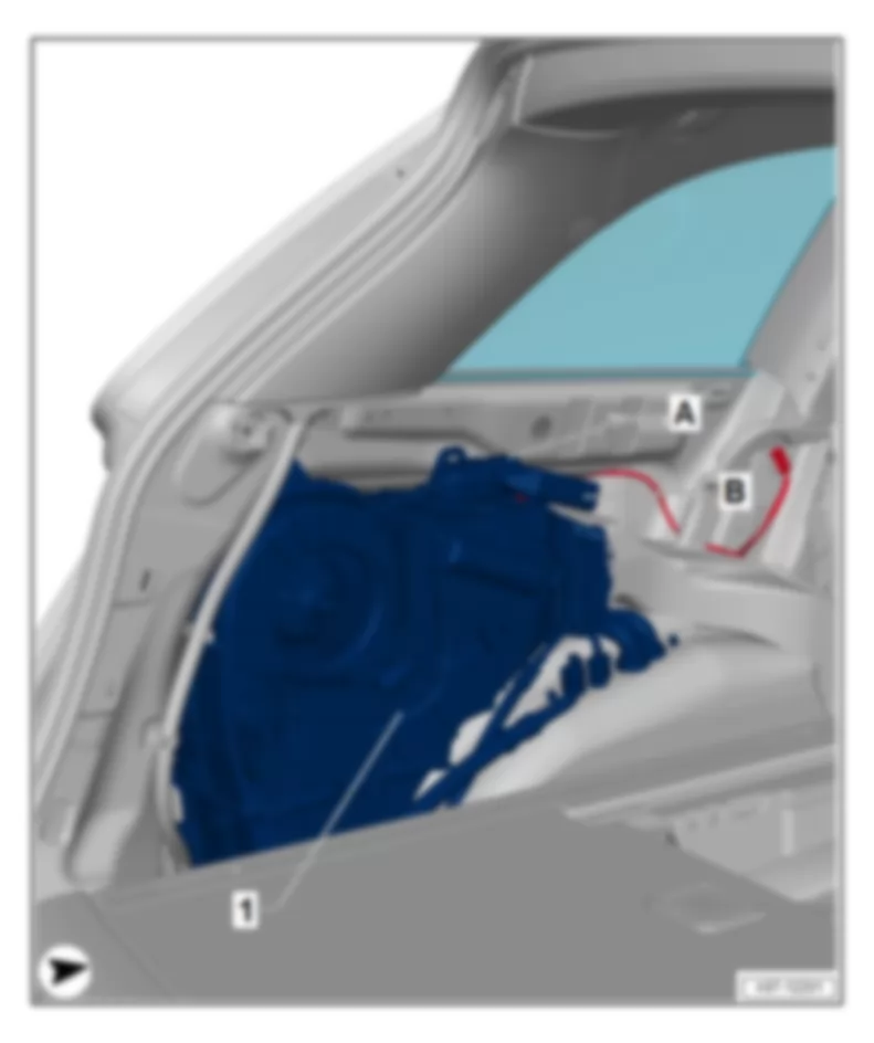
AUDI Q7 2011 Aerial reader unit for keyless entry system J723

Aerial reader unit for keyless entry system -J723-
Fitting location
   
Behind luggage compartment side trim on right -4-.
 
AUDI Q7 2011 Aerial reader unit for keyless entry system J723 https://portal-diagnostov.com/license.html
https://portal-diagnostov.com/license.html Automotive Electricians Portal FZCO Automotive Electricians Portal FZCO
Получить доступ ко всем электросхемам автомобиляDownload PDF file
Connector
AUDI Q7 2011 Aerial reader unit for keyless entry system J723 https://portal-diagnostov.com/license.html
https://portal-diagnostov.com/license.html Automotive Electricians Portal FZCO Automotive Electricians Portal FZCO
Получить доступ ко всем электросхемам автомобиляDownload PDF file
A -  20-pin connector -T20g-, red

Back to overview → chapter.


AUDI Q7 2011 TV tuner R78

TV tuner -R78-
Fitting location
   
Behind luggage compartment side trim on right -6-.
 
AUDI Q7 2011 TV tuner R78 https://portal-diagnostov.com/license.html
https://portal-diagnostov.com/license.html Automotive Electricians Portal FZCO Automotive Electricians Portal FZCO
Получить доступ ко всем электросхемам автомобиляDownload PDF file
Connectors:
A -  Connection TV1/TV2
B -  Connection TV3/TV4
C -  20-pin connector -T20p-, blue
D -  MOST bus
E -  FBAS-output
Back to overview → chapter.


AUDI Q7 2011 Aerial amplifier for mobile telephone R86

Aerial amplifier for mobile telephone -R86-
Fitting location
 
AUDI Q7 2011 Aerial amplifier for mobile telephone R86 https://portal-diagnostov.com/license.html
https://portal-diagnostov.com/license.html Automotive Electricians Portal FZCO Automotive Electricians Portal FZCO
Получить доступ ко всем электросхемам автомобиляDownload PDF file
Behind luggage compartment side trim on right -7-.
 
AUDI Q7 2011 Aerial amplifier for mobile telephone R86 https://portal-diagnostov.com/license.html
https://portal-diagnostov.com/license.html Automotive Electricians Portal FZCO Automotive Electricians Portal FZCO
Получить доступ ко всем электросхемам автомобиляDownload PDF file
Connectors up to May 2008
A -  GSM connection
B -  3-pin connector -T3r-, black
C -  Aerial connection
 
AUDI Q7 2011 Aerial amplifier for mobile telephone R86 https://portal-diagnostov.com/license.html
https://portal-diagnostov.com/license.html Automotive Electricians Portal FZCO Automotive Electricians Portal FZCO
Получить доступ ко всем электросхемам автомобиляDownload PDF file
Connectors from May 2009
A -  GSM connection
B -  Aerial connection
C -  4-pin connector -T4-, black
Back to overview → chapter.


AUDI Q7 2011 Satellite radio R146 , up to May 2009

Satellite radio -R146-, up to May 2009
Fitting location
 
AUDI Q7 2011 Satellite radio R146 , up to May 2009 https://portal-diagnostov.com/license.html
https://portal-diagnostov.com/license.html Automotive Electricians Portal FZCO Automotive Electricians Portal FZCO
Получить доступ ко всем электросхемам автомобиляDownload PDF file
Behind luggage compartment side trim on right -9-.
 
AUDI Q7 2011 Satellite radio R146 , up to May 2009 https://portal-diagnostov.com/license.html
https://portal-diagnostov.com/license.html Automotive Electricians Portal FZCO Automotive Electricians Portal FZCO
Получить доступ ко всем электросхемам автомобиляDownload PDF file
Connectors:
A -  MOST-BUS
B -  8-pin connector -T8l-, black
C -  TER connection
D -  SAT connection
Back to overview → chapter.


AUDI Q7 2011 Digital radio R147 , up to May 2009

Digital radio -R147-, up to May 2009
Fitting location
 
AUDI Q7 2011 Digital radio R147 , up to May 2009 https://portal-diagnostov.com/license.html
https://portal-diagnostov.com/license.html Automotive Electricians Portal FZCO Automotive Electricians Portal FZCO
Получить доступ ко всем электросхемам автомобиляDownload PDF file
Behind luggage compartment side trim on right -9-.
 
AUDI Q7 2011 Digital radio R147 , up to May 2009 https://portal-diagnostov.com/license.html
https://portal-diagnostov.com/license.html Automotive Electricians Portal FZCO Automotive Electricians Portal FZCO
Получить доступ ко всем электросхемам автомобиляDownload PDF file
Connectors:
A -  Connection DAB
B -  8-pin connector -T8m-, black
C -  MOST bus
Back to overview → chapter.


AUDI Q7 2011 Radio R , MMI

Radio -R-, MMI
Location, from June 2009
 
AUDI Q7 2011 Radio R , MMI https://portal-diagnostov.com/license.html
https://portal-diagnostov.com/license.html Automotive Electricians Portal FZCO Automotive Electricians Portal FZCO
Получить доступ ко всем электросхемам автомобиляDownload PDF file
Behind luggage compartment side trim on right -3-.
 
AUDI Q7 2011 Radio R , MMI https://portal-diagnostov.com/license.html
https://portal-diagnostov.com/license.html Automotive Electricians Portal FZCO Automotive Electricians Portal FZCO
Получить доступ ко всем электросхемам автомобиляDownload PDF file
Connectors up to May 2009
1 -  Connection HF
2 -  Connection ZF
3 -  MOST bus
4 -  8-pin connector -T8k-, black
 
AUDI Q7 2011 Radio R , MMI https://portal-diagnostov.com/license.html
https://portal-diagnostov.com/license.html Automotive Electricians Portal FZCO Automotive Electricians Portal FZCO
Получить доступ ко всем электросхемам автомобиляDownload PDF file
Connectors from June 2009
1 -  Connection AM/FM1/FM2
2 -  Connection DAB (Europe only)
 -  Connection SAT (USA only)
3 -  Connection block with four multi-pin connections
 -  8-pin connector -T8ag-
 -  10-pin connector -T10aa-
 -  12-pin connector -T12ad-
4 -  MOST bus
Back to overview → chapter.


AUDI Q7 2011 Control unit for parking aid J446

Control unit for parking aid -J446-
Fitting location
 
AUDI Q7 2011 Control unit for parking aid J446 https://portal-diagnostov.com/license.html
https://portal-diagnostov.com/license.html Automotive Electricians Portal FZCO Automotive Electricians Portal FZCO
Получить доступ ко всем электросхемам автомобиляDownload PDF file
Behind luggage compartment side trim on right -3-.
 
AUDI Q7 2011 Control unit for parking aid J446 https://portal-diagnostov.com/license.html
https://portal-diagnostov.com/license.html Automotive Electricians Portal FZCO Automotive Electricians Portal FZCO
Получить доступ ко всем электросхемам автомобиляDownload PDF file
Connectors:
AUDI Q7 2011 Control unit for parking aid J446 https://portal-diagnostov.com/license.html
https://portal-diagnostov.com/license.html Automotive Electricians Portal FZCO Automotive Electricians Portal FZCO
Получить доступ ко всем электросхемам автомобиляDownload PDF file
A -  16-pin connector -T16b-, brown
B -  12-pin connector -T12e-, brown
C -  12-pin connector -T12f-, black

Back to overview → chapter.


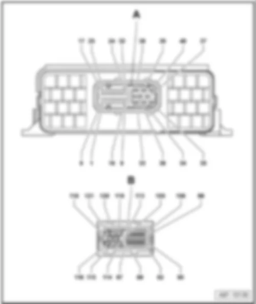
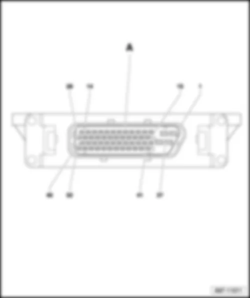
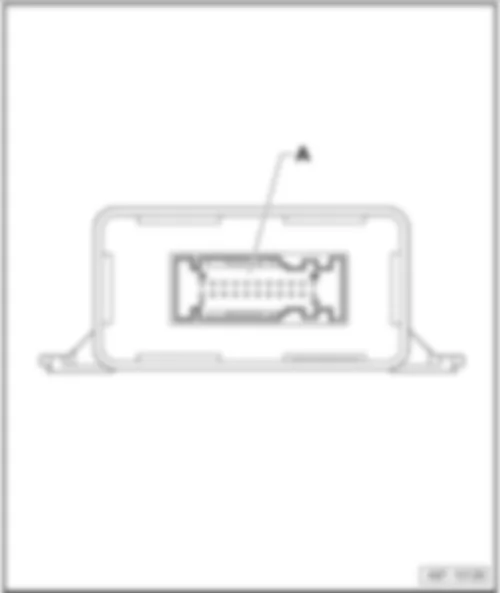
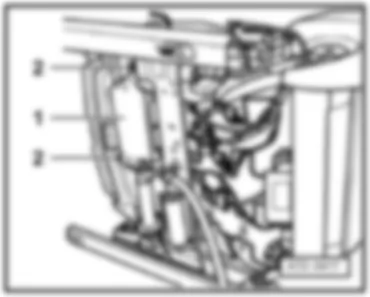
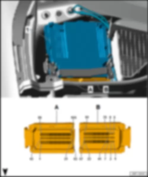
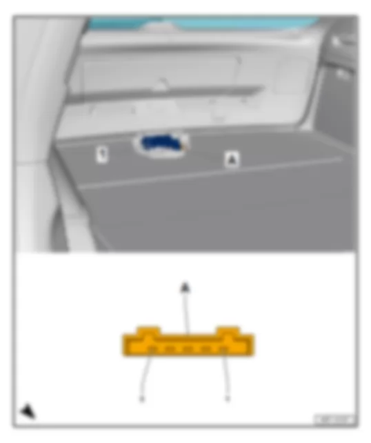
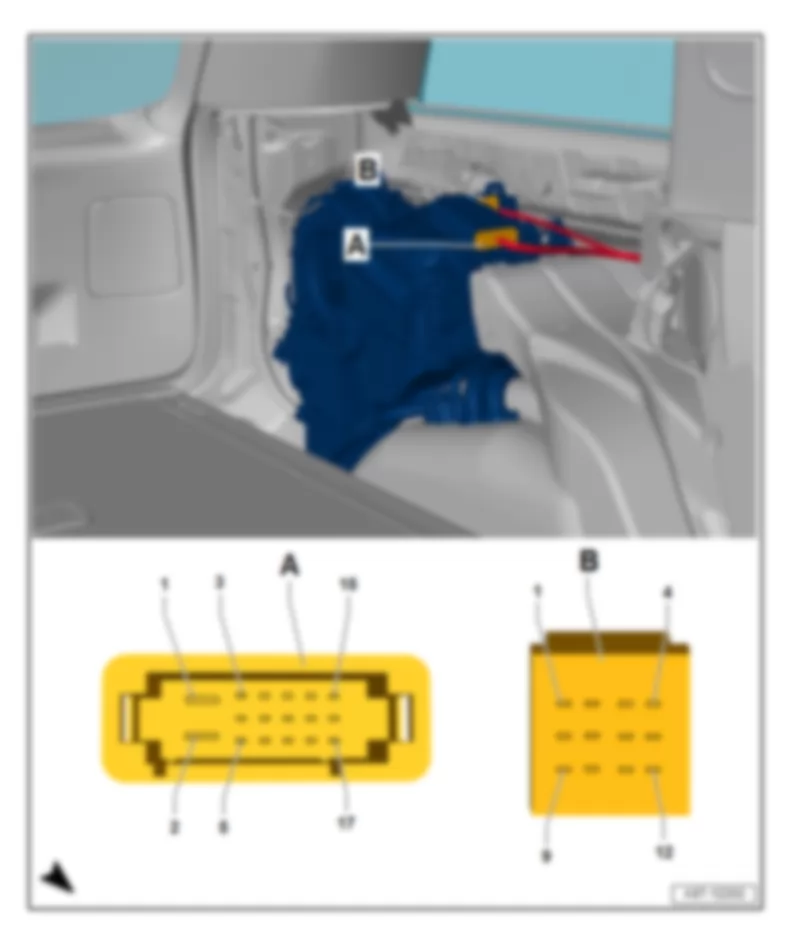
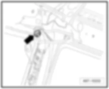
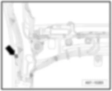
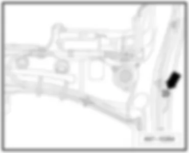
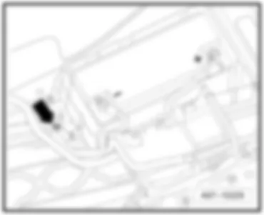
AUDI Q7 2011 Reversing camera system control unit J772

Reversing camera system control unit -J772-
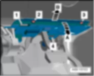
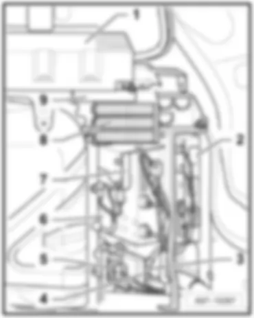
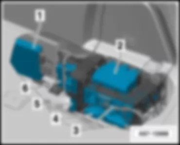
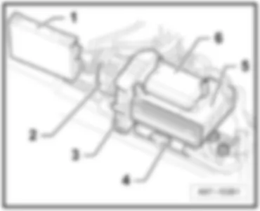
Fitting location, up to May 2009
   
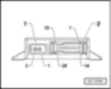
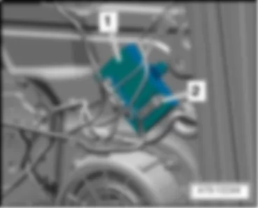
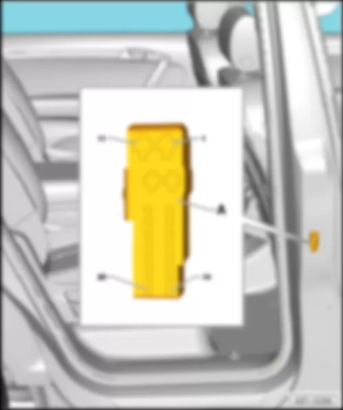
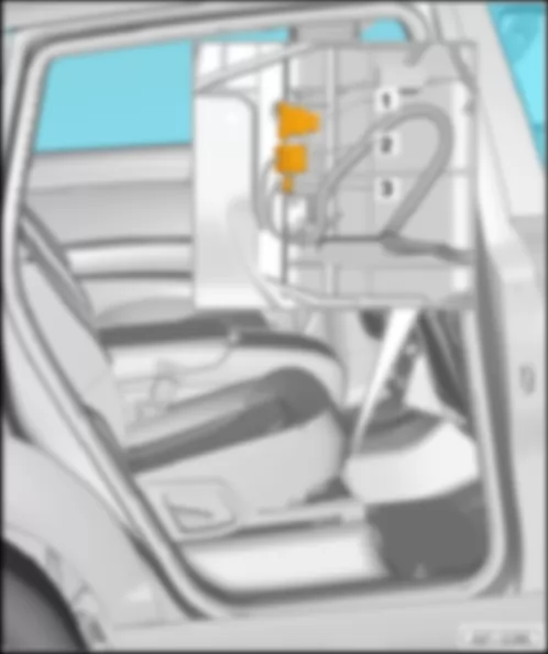
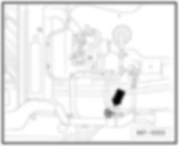
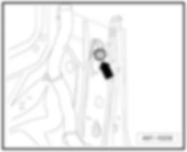
Behind luggage compartment side trim on right -1-.
Location, from June 2009
 
AUDI Q7 2011 Reversing camera system control unit J772 https://portal-diagnostov.com/license.html
https://portal-diagnostov.com/license.html Automotive Electricians Portal FZCO Automotive Electricians Portal FZCO
Получить доступ ко всем электросхемам автомобиляDownload PDF file
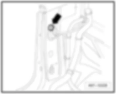
Behind luggage compartment side trim on right -1-.
 
AUDI Q7 2011 Reversing camera system control unit J772 https://portal-diagnostov.com/license.html
https://portal-diagnostov.com/license.html Automotive Electricians Portal FZCO Automotive Electricians Portal FZCO
Получить доступ ко всем электросхемам автомобиляDownload PDF file
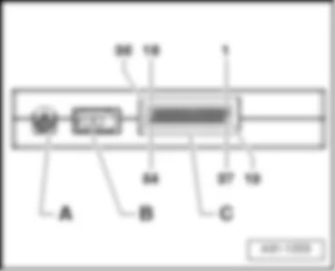
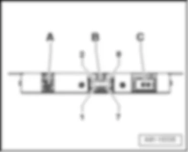
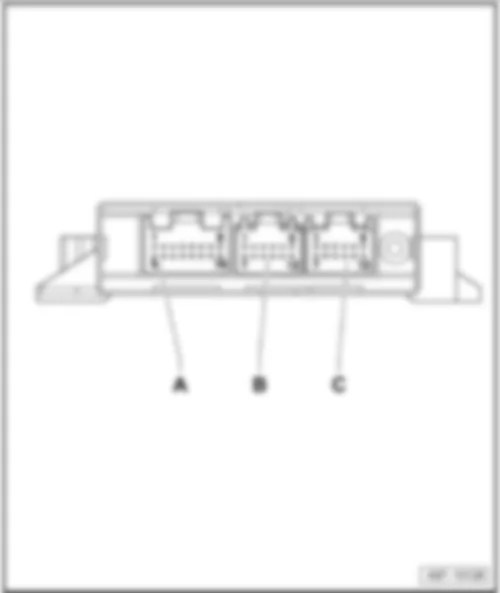
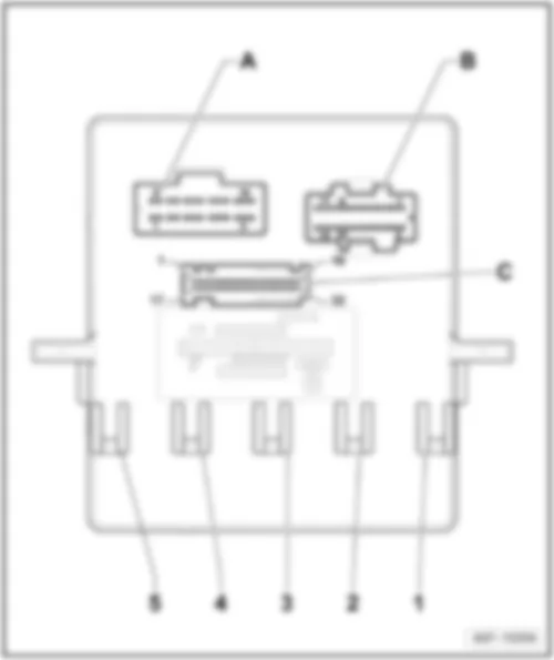
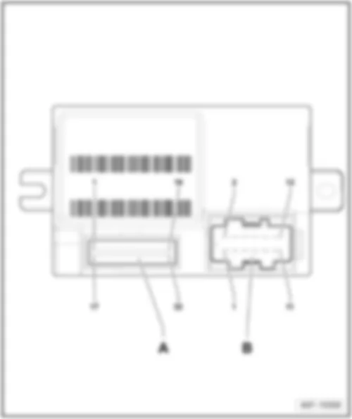
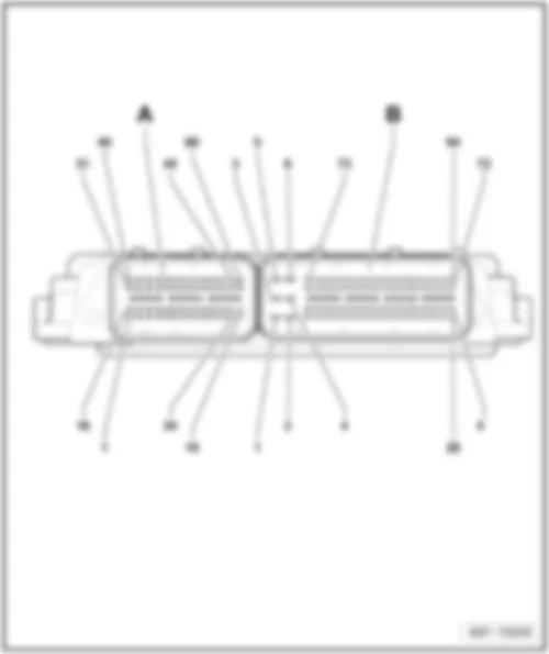
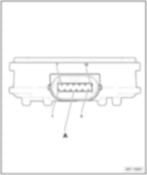
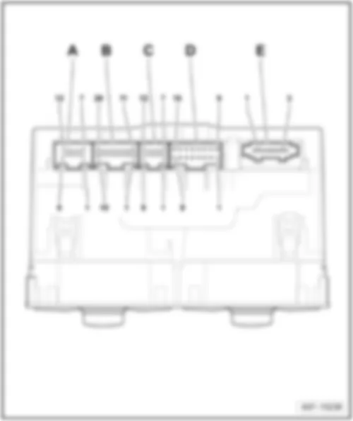
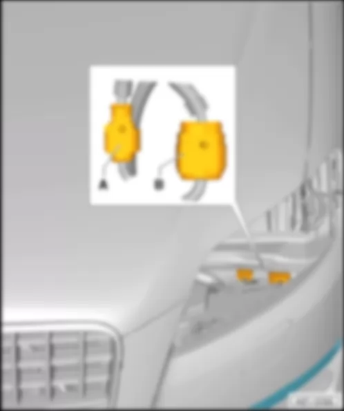
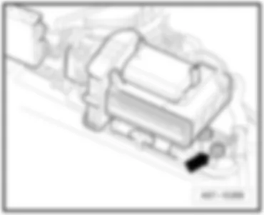
Connectors:
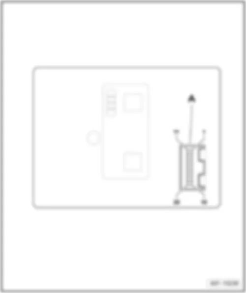
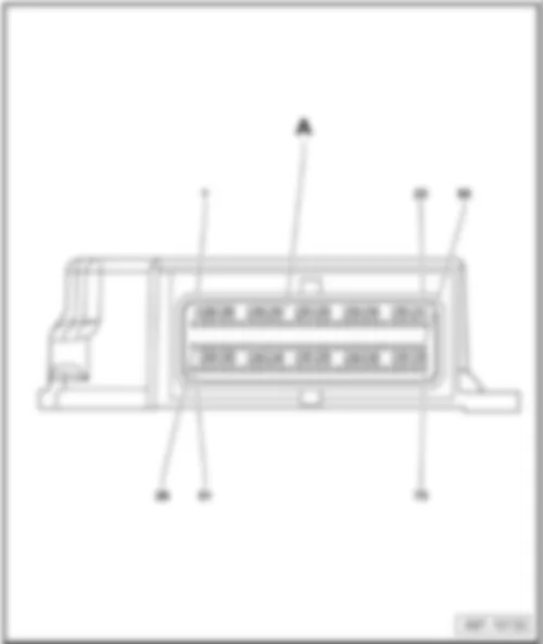
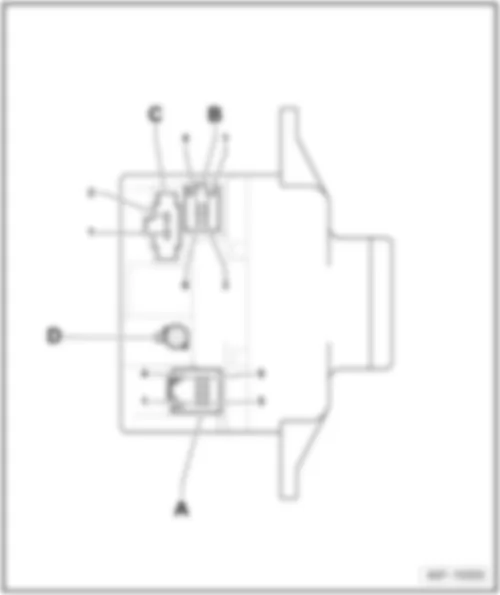
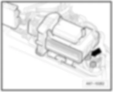
A -  54-pin connector -T54-, black
B -  FBAS-input, brown
 -  vacant from June 2009
C -  FBAS-output, green
D -  FBAS-input, grey
Back to overview → chapter.


AUDI Q7 2011 Comfort system central control unit 2 J773

Comfort system central control unit 2 -J773-
Fitting location, up to May 2009
 
AUDI Q7 2011 Comfort system central control unit 2 J773 https://portal-diagnostov.com/license.html
https://portal-diagnostov.com/license.html Automotive Electricians Portal FZCO Automotive Electricians Portal FZCO
Получить доступ ко всем электросхемам автомобиляDownload PDF file
Behind luggage compartment side trim on right -2-.
Location, from June 2009
 
AUDI Q7 2011 Comfort system central control unit 2 J773 https://portal-diagnostov.com/license.html
https://portal-diagnostov.com/license.html Automotive Electricians Portal FZCO Automotive Electricians Portal FZCO
Получить доступ ко всем электросхемам автомобиляDownload PDF file
Behind luggage compartment side trim on right -6-.
 
AUDI Q7 2011 Comfort system central control unit 2 J773 https://portal-diagnostov.com/license.html
https://portal-diagnostov.com/license.html Automotive Electricians Portal FZCO Automotive Electricians Portal FZCO
Получить доступ ко всем электросхемам автомобиляDownload PDF file
Connectors:
AUDI Q7 2011 Comfort system central control unit 2 J773 https://portal-diagnostov.com/license.html
https://portal-diagnostov.com/license.html Automotive Electricians Portal FZCO Automotive Electricians Portal FZCO
Получить доступ ко всем электросхемам автомобиляDownload PDF file
A -  6-pin, connector -T6-
B -  20-pin connector -T20f-, black
C -  16-pin connector -T16-

Back to overview → chapter.


AUDI Q7 2011 Adaptive suspension control unit J197

Adaptive suspension control unit -J197-
Fitting location, up to May 2009
   
Behind luggage compartment side trim on right -4-.
Location, from June 2009
 
AUDI Q7 2011 Adaptive suspension control unit J197 https://portal-diagnostov.com/license.html
https://portal-diagnostov.com/license.html Automotive Electricians Portal FZCO Automotive Electricians Portal FZCO
Получить доступ ко всем электросхемам автомобиляDownload PDF file
Behind luggage compartment side trim on right -4-.
 
AUDI Q7 2011 Adaptive suspension control unit J197 https://portal-diagnostov.com/license.html
https://portal-diagnostov.com/license.html Automotive Electricians Portal FZCO Automotive Electricians Portal FZCO
Получить доступ ко всем электросхемам автомобиляDownload PDF file
Connectors:
AUDI Q7 2011 Adaptive suspension control unit J197 https://portal-diagnostov.com/license.html
https://portal-diagnostov.com/license.html Automotive Electricians Portal FZCO Automotive Electricians Portal FZCO
Получить доступ ко всем электросхемам автомобиляDownload PDF file
A -  81-pin connector -T81a-, black
B -  40-pin connector -T40b-, black

Back to overview → chapter.


AUDI Q7 2011 Navigation system with CD drive control unit J401 , up to May 2009

Navigation system with CD drive control unit -J401-, up to May 2009
Fitting location, up to May 2009
   
Behind luggage compartment side trim on right -5-.
 
AUDI Q7 2011 Navigation system with CD drive control unit J401 , up to May 2009 https://portal-diagnostov.com/license.html
https://portal-diagnostov.com/license.html Automotive Electricians Portal FZCO Automotive Electricians Portal FZCO
Получить доступ ко всем электросхемам автомобиляDownload PDF file
Connectors:
A -  GPS connection, blue
B -  8-pin connector -T8n-, black
C -  MOST bus
Back to overview → chapter.


AUDI Q7 2011 Control unit for information electronics 1 J794 , from June 2009

Control unit for information electronics 1 -J794-, from June 2009
Fitting location:
 
AUDI Q7 2011 Control unit for information electronics 1 J794 , from June 2009 https://portal-diagnostov.com/license.html
https://portal-diagnostov.com/license.html Automotive Electricians Portal FZCO Automotive Electricians Portal FZCO
Получить доступ ко всем электросхемам автомобиляDownload PDF file
in the dash panel.
 
AUDI Q7 2011 Control unit for information electronics 1 J794 , from June 2009 https://portal-diagnostov.com/license.html
https://portal-diagnostov.com/license.html Automotive Electricians Portal FZCO Automotive Electricians Portal FZCO
Получить доступ ко всем электросхемам автомобиляDownload PDF file
Connectors:
1 -  Connection block with four multi-pin connections
 -  8-pin connector -T8ae-
 -  8-pin connector -T8af-
 -  12-pin connector -T12ab-
2 -  MOST-BUS
3 -  FBAS-input
4 -  4-pin connector -T4av-
5 -  4-pin connector -T4au-
6 -  Vacant
7 -  GPS connection
8 -  GSM connection
Back to overview → chapter.


AUDI Q7 2011 Trailer detector control unit J345

Trailer detector control unit -J345-
Fitting location, up to May 2009
 
AUDI Q7 2011 Trailer detector control unit J345 https://portal-diagnostov.com/license.html
https://portal-diagnostov.com/license.html Automotive Electricians Portal FZCO Automotive Electricians Portal FZCO
Получить доступ ко всем электросхемам автомобиляDownload PDF file
Behind luggage compartment side trim on right -6-.
Location, from June 2009
 
AUDI Q7 2011 Trailer detector control unit J345 https://portal-diagnostov.com/license.html
https://portal-diagnostov.com/license.html Automotive Electricians Portal FZCO Automotive Electricians Portal FZCO
Получить доступ ко всем электросхемам автомобиляDownload PDF file
Behind luggage compartment side trim on right -2-.
 
AUDI Q7 2011 Trailer detector control unit J345 https://portal-diagnostov.com/license.html
https://portal-diagnostov.com/license.html Automotive Electricians Portal FZCO Automotive Electricians Portal FZCO
Получить доступ ко всем электросхемам автомобиляDownload PDF file
Connectors:
AUDI Q7 2011 Trailer detector control unit J345 https://portal-diagnostov.com/license.html
https://portal-diagnostov.com/license.html Automotive Electricians Portal FZCO Automotive Electricians Portal FZCO
Получить доступ ко всем электросхемам автомобиляDownload PDF file
A -  16-pin connector -T16e-, black
B -  12-pin connector -T12d-, red
C -  12-pin connector -T12c-, blue

Back to overview → chapter.


AUDI Q7 2011 Control unit for headlight range control J431

Control unit for headlight range control -J431-
Fitting location
   
Behind shelf on front passenger side -1-.
 
AUDI Q7 2011 Control unit for headlight range control J431 https://portal-diagnostov.com/license.html
https://portal-diagnostov.com/license.html Automotive Electricians Portal FZCO Automotive Electricians Portal FZCO
Получить доступ ко всем электросхемам автомобиляDownload PDF file
Connector
AUDI Q7 2011 Control unit for headlight range control J431 https://portal-diagnostov.com/license.html
https://portal-diagnostov.com/license.html Automotive Electricians Portal FZCO Automotive Electricians Portal FZCO
Получить доступ ко всем электросхемам автомобиляDownload PDF file
A -  26-pin connector -T26a-, black

Back to overview → chapter.


AUDI Q7 2011 Comfort system central control unit J393

Comfort system central control unit -J393-
Fitting location, up to May 2009
   
Behind luggage compartment side trim on right -3-.
Location, from June 2009
 
AUDI Q7 2011 Comfort system central control unit J393 https://portal-diagnostov.com/license.html
https://portal-diagnostov.com/license.html Automotive Electricians Portal FZCO Automotive Electricians Portal FZCO
Получить доступ ко всем электросхемам автомобиляDownload PDF file
Behind luggage compartment side trim on right -5-.
 
AUDI Q7 2011 Comfort system central control unit J393 https://portal-diagnostov.com/license.html
https://portal-diagnostov.com/license.html Automotive Electricians Portal FZCO Automotive Electricians Portal FZCO
Получить доступ ко всем электросхемам автомобиляDownload PDF file
Connectors:
AUDI Q7 2011 Comfort system central control unit J393 https://portal-diagnostov.com/license.html
https://portal-diagnostov.com/license.html Automotive Electricians Portal FZCO Automotive Electricians Portal FZCO
Получить доступ ко всем электросхемам автомобиляDownload PDF file
A -  15-pin connector -T15a-, brown
B -  10-pin connector -T10g-, black
C -  32-pin connector -T32d-, blue

Back to overview → chapter.


AUDI Q7 2011 Data bus diagnostic interface J533

Data bus diagnostic interface -J533-
Fitting location
   
Behind shelf on front passenger side -2-.
 
AUDI Q7 2011 Data bus diagnostic interface J533 https://portal-diagnostov.com/license.html
https://portal-diagnostov.com/license.html Automotive Electricians Portal FZCO Automotive Electricians Portal FZCO
Получить доступ ко всем электросхемам автомобиляDownload PDF file
Connectors up to May 2008
1 -  MOST bus
2 -  26-pin connector -T26b-, black
 
AUDI Q7 2011 Data bus diagnostic interface J533 https://portal-diagnostov.com/license.html
https://portal-diagnostov.com/license.html Automotive Electricians Portal FZCO Automotive Electricians Portal FZCO
Получить доступ ко всем электросхемам автомобиляDownload PDF file
Connectors from June 2008
1 -  MOST bus
2 -  20-pin connector -T20-, black
Back to overview → chapter.


AUDI Q7 2011 onboard supply control unit J519

onboard supply control unit -J519-
Fitting location
 
AUDI Q7 2011 onboard supply control unit J519 https://portal-diagnostov.com/license.html
https://portal-diagnostov.com/license.html Automotive Electricians Portal FZCO Automotive Electricians Portal FZCO
Получить доступ ко всем электросхемам автомобиляDownload PDF file
Behind shelf on front passenger side -4-.
 
AUDI Q7 2011 onboard supply control unit J519 https://portal-diagnostov.com/license.html
https://portal-diagnostov.com/license.html Automotive Electricians Portal FZCO Automotive Electricians Portal FZCO
Получить доступ ко всем электросхемам автомобиляDownload PDF file
Connectors:
AUDI Q7 2011 onboard supply control unit J519 https://portal-diagnostov.com/license.html
https://portal-diagnostov.com/license.html Automotive Electricians Portal FZCO Automotive Electricians Portal FZCO
Получить доступ ко всем электросхемам автомобиляDownload PDF file
A -  10-pin connector -T10a-, black
B -  12-pin connector -T12b-, black
C -  32-pin connector -T32b-, grey

Back to overview → chapter.


AUDI Q7 2011 Tyre pressure monitor control unit J502

Tyre pressure monitor control unit -J502-
Fitting location
   
Behind shelf on front passenger side -3-.
 
AUDI Q7 2011 Tyre pressure monitor control unit J502 https://portal-diagnostov.com/license.html
https://portal-diagnostov.com/license.html Automotive Electricians Portal FZCO Automotive Electricians Portal FZCO
Получить доступ ко всем электросхемам автомобиляDownload PDF file
Connector
AUDI Q7 2011 Tyre pressure monitor control unit J502 https://portal-diagnostov.com/license.html
https://portal-diagnostov.com/license.html Automotive Electricians Portal FZCO Automotive Electricians Portal FZCO
Получить доступ ко всем электросхемам автомобиляDownload PDF file
A -  32-pin connector -T32e-, white

Back to overview → chapter.


AUDI Q7 2011 Energy management control unit J644 , up to May 2008

Energy management control unit -J644-, up to May 2008
Fitting location
   
Next to battery -A- Under driver seat -5-.
Connector
 
AUDI Q7 2011 Energy management control unit J644 , up to May 2008 https://portal-diagnostov.com/license.html
https://portal-diagnostov.com/license.html Automotive Electricians Portal FZCO Automotive Electricians Portal FZCO
Получить доступ ко всем электросхемам автомобиляDownload PDF file
AUDI Q7 2011 Energy management control unit J644 , up to May 2008 https://portal-diagnostov.com/license.html
https://portal-diagnostov.com/license.html Automotive Electricians Portal FZCO Automotive Electricians Portal FZCO
Получить доступ ко всем электросхемам автомобиляDownload PDF file
A -  14-pin connector -T14-

Back to overview → chapter.


AUDI Q7 2011 Battery monitor control unit J367 , from June 2008

Battery monitor control unit -J367-, from June 2008
Fitting location
   
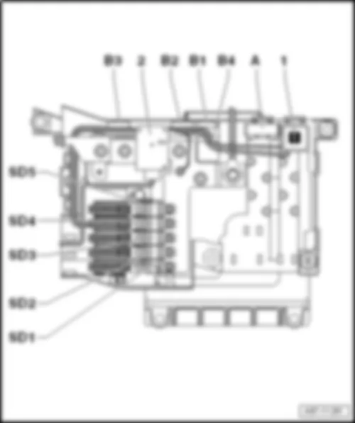
On negative terminal ofbattery -A--1-.
1 -  Battery monitor control unit -J367-
2 -  2-pin connector -T2az-, black
3 -  Battery negative terminal
Back to overview → chapter.


AUDI Q7 2011 Remote control receiver for auxiliary heater R64

Remote control receiver for auxiliary heater -R64-
Fitting location
 
AUDI Q7 2011 Remote control receiver for auxiliary heater R64 https://portal-diagnostov.com/license.html
https://portal-diagnostov.com/license.html Automotive Electricians Portal FZCO Automotive Electricians Portal FZCO
Получить доступ ко всем электросхемам автомобиляDownload PDF file
Behind luggage compartment side trim on right -5-.
 
AUDI Q7 2011 Remote control receiver for auxiliary heater R64 https://portal-diagnostov.com/license.html
https://portal-diagnostov.com/license.html Automotive Electricians Portal FZCO Automotive Electricians Portal FZCO
Получить доступ ко всем электросхемам автомобиляDownload PDF file
Connectors:
A -  6-pin, connector -T6u-, blue
B -  Aerial connection
Back to overview → chapter.


AUDI Q7 2011 Control unit for seat adjustment and steering column adjustment with memory function J136 / control unit for front passenger seat adjustment with memory function J521

Control unit for seat adjustment and steering column adjustment with memory function -J136-/control unit for front passenger seat adjustment with memory function -J521-
Fitting location
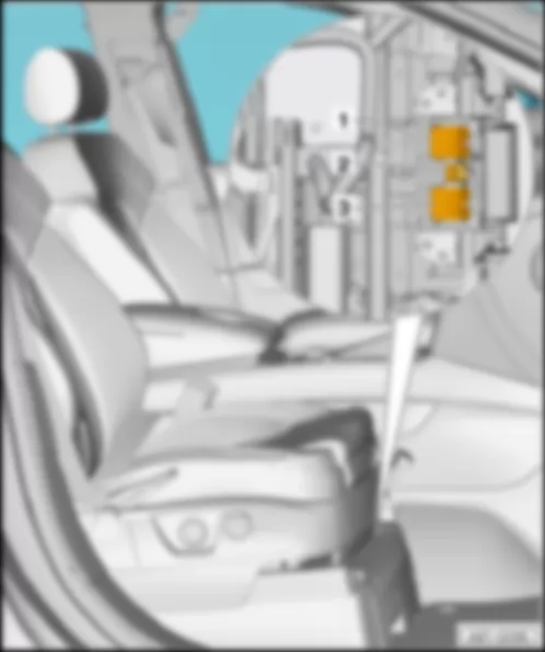
Control unit for seat adjustment and steering column adjustment with memory function -J136- Under driver seat -1-
 
AUDI Q7 2011 Control unit for seat adjustment and steering column adjustment with memory function J136 / control unit for front passenger seat adjustment with memory function J521 https://portal-diagnostov.com/license.html
https://portal-diagnostov.com/license.html Automotive Electricians Portal FZCO Automotive Electricians Portal FZCO
Получить доступ ко всем электросхемам автомобиляDownload PDF file
Front passenger seat adjustment with memory control unit -J521- Under front passenger seat -1-
Connectors:
 
AUDI Q7 2011 Control unit for seat adjustment and steering column adjustment with memory function J136 / control unit for front passenger seat adjustment with memory function J521 https://portal-diagnostov.com/license.html
https://portal-diagnostov.com/license.html Automotive Electricians Portal FZCO Automotive Electricians Portal FZCO
Получить доступ ко всем электросхемам автомобиляDownload PDF file
A -  32-pin connector -T32h-/32-pin connector -T32i-, blue
B -  12-pin connector -T12s-/12-pin connector -T12t-, black

Back to overview → chapter.


AUDI Q7 2011 Engine control unit J623

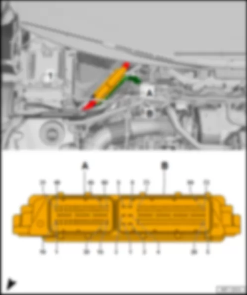
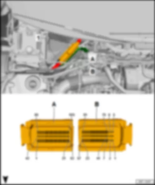
Engine control unit -J623-
Engine control unit -J623-, with 154-pin connector → anchor
Engine control unit -J623-, with 196-pin connector → anchor
Engine control unit -J623-, with 154-pin connector
   
Fitting location
On right in plenum chamber -1-.
 
AUDI Q7 2011 Engine control unit J623 https://portal-diagnostov.com/license.html
https://portal-diagnostov.com/license.html Automotive Electricians Portal FZCO Automotive Electricians Portal FZCO
Получить доступ ко всем электросхемам автомобиляDownload PDF file
Connectors:
AUDI Q7 2011 Engine control unit J623 https://portal-diagnostov.com/license.html
https://portal-diagnostov.com/license.html Automotive Electricians Portal FZCO Automotive Electricians Portal FZCO
Получить доступ ко всем электросхемам автомобиляDownload PDF file
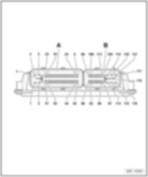
A -  60-pin connector -T60-, black
B -  94-pin connector -T94-, black

Back to overview → chapter.
   
Engine control unit -J623-, with 196-pin connector
Fitting location
On right in plenum chamber -1-.
AUDI Q7 2011 Engine control unit J623 https://portal-diagnostov.com/license.html
https://portal-diagnostov.com/license.html Automotive Electricians Portal FZCO Automotive Electricians Portal FZCO
Получить доступ ко всем электросхемам автомобиляDownload PDF file
1 -  Engine control unit -J623-
A -  105-pin connector -T105-, black
B -  91-pin connector -T91-, black

Back to overview → chapter.


AUDI Q7 2011 Engine control unit 2 J624

Engine control unit 2 -J624-
Engine control unit 2 -J624-, with 154-pin connector → chapter
Engine control unit 2 -J624-, with 196-pin connector → chapter
   
Engine control unit 2 -J624-, with 154-pin connector
Fitting location
On right in plenum chamber -1-.
AUDI Q7 2011 Engine control unit 2 J624 https://portal-diagnostov.com/license.html
https://portal-diagnostov.com/license.html Automotive Electricians Portal FZCO Automotive Electricians Portal FZCO
Получить доступ ко всем электросхемам автомобиляDownload PDF file
1 -  Engine control unit -J624-
A -  60-pin connector -T60-, black
B -  94-pin connector -T94-, black

Back to overview → chapter.
   
Engine control unit 2 -J624-, with 196-pin connector
Fitting location
On right in plenum chamber -1-
AUDI Q7 2011 Engine control unit 2 J624 https://portal-diagnostov.com/license.html
https://portal-diagnostov.com/license.html Automotive Electricians Portal FZCO Automotive Electricians Portal FZCO
Получить доступ ко всем электросхемам автомобиляDownload PDF file
1 -  Engine control unit -J624-
A -  105-pin connector -T105-, black
B -  91-pin connector -T91-, black

Back to overview → chapter.


AUDI Q7 2011 Lane change assist control unit J769 / lane change assist control unit 2 J770

Lane change assist control unit -J769-/lane change assist control unit 2 -J770-
Fitting location
   
In rear bumper cover -4-.
Connector
 
AUDI Q7 2011 Lane change assist control unit J769 / lane change assist control unit 2 J770 https://portal-diagnostov.com/license.html
https://portal-diagnostov.com/license.html Automotive Electricians Portal FZCO Automotive Electricians Portal FZCO
Получить доступ ко всем электросхемам автомобиляDownload PDF file
A -  12-pin connector -T12l-, black
A -  12-pin connector -T12m-, black

Back to overview → chapter.


AUDI Q7 2011 Sliding sunroof motor V1

Sliding sunroof motor -V1-
Connector
AUDI Q7 2011 Sliding sunroof motor V1 https://portal-diagnostov.com/license.html
https://portal-diagnostov.com/license.html Automotive Electricians Portal FZCO Automotive Electricians Portal FZCO
Получить доступ ко всем электросхемам автомобиляDownload PDF file
A -  16-pin connector -T16n-, black

Back to overview → chapter.
Airbag control unit -J234-
Fitting location
   
Under lower centre console -3-.
Connector
 
AUDI Q7 2011 Sliding sunroof motor V1 https://portal-diagnostov.com/license.html
https://portal-diagnostov.com/license.html Automotive Electricians Portal FZCO Automotive Electricians Portal FZCO
Получить доступ ко всем электросхемам автомобиляDownload PDF file
AUDI Q7 2011 Sliding sunroof motor V1 https://portal-diagnostov.com/license.html
https://portal-diagnostov.com/license.html Automotive Electricians Portal FZCO Automotive Electricians Portal FZCO
Получить доступ ко всем электросхемам автомобиляDownload PDF file
A -  75-pin connector -T75-, grey, USA: white

Back to overview → chapter.


AUDI Q7 2011 Driver door control unit J386

Driver door control unit -J386-
Fitting location
   
In driver door -1-.
Connectors:
 
AUDI Q7 2011 Driver door control unit J386 https://portal-diagnostov.com/license.html
https://portal-diagnostov.com/license.html Automotive Electricians Portal FZCO Automotive Electricians Portal FZCO
Получить доступ ко всем электросхемам автомобиляDownload PDF file
AUDI Q7 2011 Driver door control unit J386 https://portal-diagnostov.com/license.html
https://portal-diagnostov.com/license.html Automotive Electricians Portal FZCO Automotive Electricians Portal FZCO
Получить доступ ко всем электросхемам автомобиляDownload PDF file
A -  6-pin, connector -T6ac-, black
B -  20-pin connector -T20l-, black
C -  16-pin connector -T16i-, black
D -  32-pin connector -T32f-, white

Back to overview → chapter.


AUDI Q7 2011 Front passenger door control unit J387

Front passenger door control unit -J387-
Fitting location
   
In front passenger door -1-.
Connectors:
 
AUDI Q7 2011 Front passenger door control unit J387 https://portal-diagnostov.com/license.html
https://portal-diagnostov.com/license.html Automotive Electricians Portal FZCO Automotive Electricians Portal FZCO
Получить доступ ко всем электросхемам автомобиляDownload PDF file
AUDI Q7 2011 Front passenger door control unit J387 https://portal-diagnostov.com/license.html
https://portal-diagnostov.com/license.html Automotive Electricians Portal FZCO Automotive Electricians Portal FZCO
Получить доступ ко всем электросхемам автомобиляDownload PDF file
A -  6-pin, connector -T6ad-, black
B -  20-pin connector -T20m-, black
C -  16-pin connector -T16k-, black
D -  32-pin connector -T32g-, white

Back to overview → chapter.


AUDI Q7 2011 Rear left door control unit J388

Rear left door control unit -J388-
Fitting location
   
In rear left door -1-.
Connectors:
 
AUDI Q7 2011 Rear left door control unit J388 https://portal-diagnostov.com/license.html
https://portal-diagnostov.com/license.html Automotive Electricians Portal FZCO Automotive Electricians Portal FZCO
Получить доступ ко всем электросхемам автомобиляDownload PDF file
AUDI Q7 2011 Rear left door control unit J388 https://portal-diagnostov.com/license.html
https://portal-diagnostov.com/license.html Automotive Electricians Portal FZCO Automotive Electricians Portal FZCO
Получить доступ ко всем электросхемам автомобиляDownload PDF file
A -  6-pin, connector -T6ae-, black
B -  20-pin connector -T20n-, black
C -  16-pin connector -T16l-, black
D -  Vacant

Back to overview → chapter.


AUDI Q7 2011 Rear right door control unit J389

Rear right door control unit -J389-
Fitting location
   
In rear right door -1-.
Connectors:
 
AUDI Q7 2011 Rear right door control unit J389 https://portal-diagnostov.com/license.html
https://portal-diagnostov.com/license.html Automotive Electricians Portal FZCO Automotive Electricians Portal FZCO
Получить доступ ко всем электросхемам автомобиляDownload PDF file
AUDI Q7 2011 Rear right door control unit J389 https://portal-diagnostov.com/license.html
https://portal-diagnostov.com/license.html Automotive Electricians Portal FZCO Automotive Electricians Portal FZCO
Получить доступ ко всем электросхемам автомобиляDownload PDF file
A -  6-pin, connector -T6af-, black
B -  20-pin connector -T20o-, black
C -  16-pin connector -T16m-, black
D -  Vacant

Back to overview → chapter.


AUDI Q7 2011 Entry​and​start​authorisation​switch E415

Entry​and​start​authorisation​switch -E415-
Fitting location
   
In centre console, on right next to steering wheel -1-.
Connectors:
 
AUDI Q7 2011 Entry​and​start​authorisation​switch E415 https://portal-diagnostov.com/license.html
https://portal-diagnostov.com/license.html Automotive Electricians Portal FZCO Automotive Electricians Portal FZCO
Получить доступ ко всем электросхемам автомобиляDownload PDF file
AUDI Q7 2011 Entry​and​start​authorisation​switch E415 https://portal-diagnostov.com/license.html
https://portal-diagnostov.com/license.html Automotive Electricians Portal FZCO Automotive Electricians Portal FZCO
Получить доступ ко всем электросхемам автомобиляDownload PDF file
A -  8-pin connector -T8a-, black
B -  6-pin, connector -T6a-, black
C -  2-pin connector -T2a-, black
D -  Aerial connection

Back to overview → chapter.


AUDI Q7 2011 Climatronic control unit J255 , comfort level air conditioning system

Climatronic control unit -J255-, comfort level air conditioning system
Fitting location
   
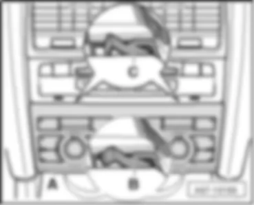
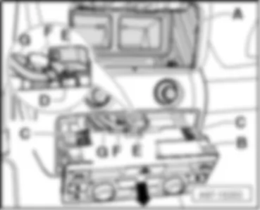
In upper centre console -A-.
Connectors:
 
AUDI Q7 2011 Climatronic control unit J255 , comfort level air conditioning system https://portal-diagnostov.com/license.html
https://portal-diagnostov.com/license.html Automotive Electricians Portal FZCO Automotive Electricians Portal FZCO
Получить доступ ко всем электросхемам автомобиляDownload PDF file
A -  12-pin connector -T12g-
B -  20-pin connector -T20i-, red
C -  16-pin connector -T16c-, brown
D -  16-pin connector -T16d-, black
E -  3-pin connector -T3c-, black

Back to overview → chapter.


AUDI Q7 2011 Climatronic control unit J255 , basic level air conditioning system

Climatronic control unit -J255-, basic level air conditioning system
Fitting location
   
In upper centre console -A-.
Connectors:
 
AUDI Q7 2011 Climatronic control unit J255 , basic level air conditioning system https://portal-diagnostov.com/license.html
https://portal-diagnostov.com/license.html Automotive Electricians Portal FZCO Automotive Electricians Portal FZCO
Получить доступ ко всем электросхемам автомобиляDownload PDF file
A -  Vacant
B -  20-pin connector -T20i-, red
C -  Vacant
D -  16-pin connector -T16d-, black
E -  3-pin connector -T3c-, black

Back to overview → chapter.


AUDI Q7 2011 Rear Climatronic operating and display unit E265

Rear Climatronic operating and display unit -E265-
Fitting location
   
In rear centre console -B-.
Connectors:
 
AUDI Q7 2011 Rear Climatronic operating and display unit E265 https://portal-diagnostov.com/license.html
https://portal-diagnostov.com/license.html Automotive Electricians Portal FZCO Automotive Electricians Portal FZCO
Получить доступ ко всем электросхемам автомобиляDownload PDF file
AUDI Q7 2011 Rear Climatronic operating and display unit E265 https://portal-diagnostov.com/license.html
https://portal-diagnostov.com/license.html Automotive Electricians Portal FZCO Automotive Electricians Portal FZCO
Получить доступ ко всем электросхемам автомобиляDownload PDF file
A -  12-pin connector -T12h-, black
B -  20-pin connector -T20h-, red
C -  Vacant
D -  16-pin connector -T16h-, black
E -  3-pin connector -T3h-, black

Back to overview → chapter.


AUDI Q7 2011 Control unit in dash panel insert J285

Control unit in dash panel insert -J285-
Fitting location
in driver side dash panel.
   
AUDI Q7 2011 Control unit in dash panel insert J285 https://portal-diagnostov.com/license.html
https://portal-diagnostov.com/license.html Automotive Electricians Portal FZCO Automotive Electricians Portal FZCO
Получить доступ ко всем электросхемам автомобиляDownload PDF file
A -  32-pin connector -T32a-, green
B -  Control unit in dash panel insert -J285-

Back to overview → chapter.


AUDI Q7 2011 Fuel pump control unit J538

Fuel pump control unit -J538-
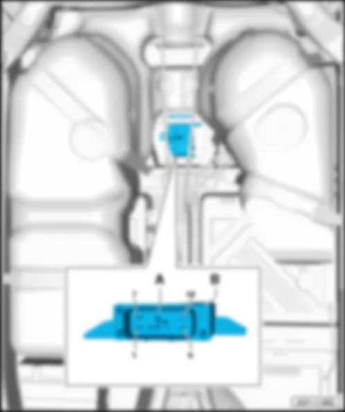
Fitting location
at rear of fuel tank.
   
AUDI Q7 2011 Fuel pump control unit J538 https://portal-diagnostov.com/license.html
https://portal-diagnostov.com/license.html Automotive Electricians Portal FZCO Automotive Electricians Portal FZCO
Получить доступ ко всем электросхемам автомобиляDownload PDF file
A -  12-pin connector -T12-, black
B -  Fuel pump control unit -J538-

Back to overview → chapter.


AUDI Q7 2011 Control unit for reducing agent metering system J880

Control unit for reducing agent metering system -J880-
Fitting location
Under bench seat cushion in right area -1-
AUDI Q7 2011 Control unit for reducing agent metering system J880 https://portal-diagnostov.com/license.html
https://portal-diagnostov.com/license.html Automotive Electricians Portal FZCO Automotive Electricians Portal FZCO
Получить доступ ко всем электросхемам автомобиляDownload PDF file
1 -  Control unit for reducing agent metering system -J880-
A -  30-pin connector -T30-

   
Connector assignment for reducing agent metering system control unit -J880-
T30 Designation    
1 Vacant 16 Sensor ground
2 Power supply sensor 17 Pump heater
3 Vacant 18 Terminal 31
4 Vacant 19 Filling level signal
5 Vacant 20 Sensor ground
6 Vacant 21 Vacant
7 Vacant 22 Diagnosis, heater 2
8 Heating command 1 23 Vacant
9 Heating command 2 24 Diagnosis, heater 1
10 Sensor 5V 25 Transfer pump command
11 Sensor ground 26 Power supply for transfer pump
12 Vacant 27 Vacant
13 Vacant 28 Vacant
14 Tank heater 29 Vacant
15 Line heater 30 Vacant

Back to overview → chapter.


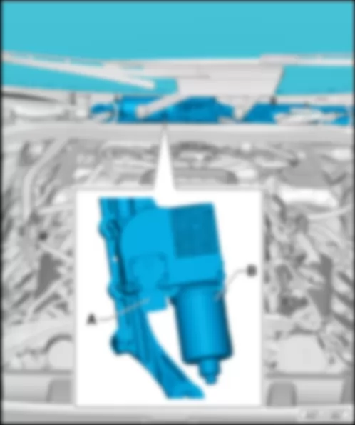
AUDI Q7 2011 Wiper motor control unit J400

Wiper motor control unit -J400-
Fitting location
in plenum chamber.
   
AUDI Q7 2011 Wiper motor control unit J400 https://portal-diagnostov.com/license.html
https://portal-diagnostov.com/license.html Automotive Electricians Portal FZCO Automotive Electricians Portal FZCO
Получить доступ ко всем электросхемам автомобиляDownload PDF file
A -  4-pin connector -T4-, black
B -  Wiper motor control unit -J400-

Back to overview → chapter.


AUDI Q7 2011 Sliding sunroof adjustment control unit J245

Sliding sunroof adjustment control unit -J245-
Fitting location
Near front interior light -W1-.
   
AUDI Q7 2011 Sliding sunroof adjustment control unit J245 https://portal-diagnostov.com/license.html
https://portal-diagnostov.com/license.html Automotive Electricians Portal FZCO Automotive Electricians Portal FZCO
Получить доступ ко всем электросхемам автомобиляDownload PDF file
A -  Sliding sunroof adjustment control unit -J245-
q   with sliding sunroof motor -V1-
B -  16-pin connector -T16n-, black

Back to overview → chapter.


AUDI Q7 2011 Rear sliding sunroof control unit J392

Rear sliding sunroof control unit -J392-
Fitting location
at rear of panoramic roof.
   
AUDI Q7 2011 Rear sliding sunroof control unit J392 https://portal-diagnostov.com/license.html
https://portal-diagnostov.com/license.html Automotive Electricians Portal FZCO Automotive Electricians Portal FZCO
Получить доступ ко всем электросхемам автомобиляDownload PDF file
A -  Rear sliding sunroof control unit -J392-
q   with rear sliding sunroof motor -V146-
B -  16-pin connector -T16o-, black

Back to overview → chapter.


AUDI Q7 2011 Sunroof roller blind control unit J394

Sunroof roller blind control unit -J394-
Fitting location
at rear of panoramic roof.
   
AUDI Q7 2011 Sunroof roller blind control unit J394 https://portal-diagnostov.com/license.html
https://portal-diagnostov.com/license.html Automotive Electricians Portal FZCO Automotive Electricians Portal FZCO
Получить доступ ко всем электросхемам автомобиляDownload PDF file
A -  Sunroof roller blind control unit -J394-
q   with sunroof roller blind motor -V260-
B -  16-pin connector -T16p-, black

Back to overview → chapter.


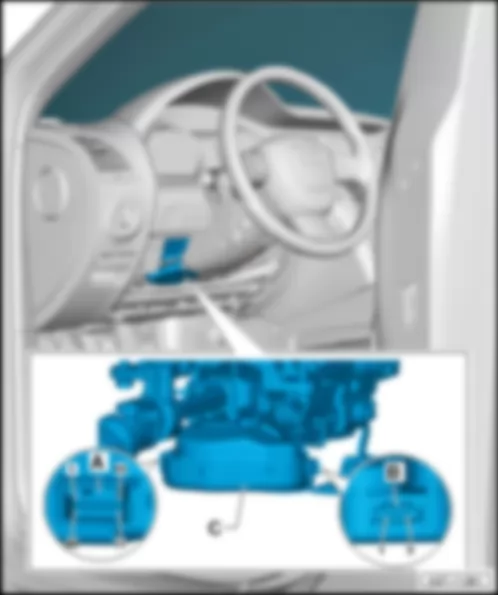
AUDI Q7 2011 Entry and start authorisation control unit J518

Entry and start authorisation control unit -J518-
Fitting location
On steering column.
   
AUDI Q7 2011 Entry and start authorisation control unit J518 https://portal-diagnostov.com/license.html
https://portal-diagnostov.com/license.html Automotive Electricians Portal FZCO Automotive Electricians Portal FZCO
Получить доступ ко всем электросхемам автомобиляDownload PDF file
A -  20-pin connector -T20e-, black
B -  3-pin connector -T3a-, black
C -  Entry and start authorisation control unit -J518-

Back to overview → chapter.


AUDI Q7 2011 Control unit for adaptive cruise control J428

Control unit for adaptive cruise control -J428-
Fitting location
behind radiator grille on right.
   
AUDI Q7 2011 Control unit for adaptive cruise control J428 https://portal-diagnostov.com/license.html
https://portal-diagnostov.com/license.html Automotive Electricians Portal FZCO Automotive Electricians Portal FZCO
Получить доступ ко всем электросхемам автомобиляDownload PDF file
A -  8-pin connector -T8-, black
B -  Control unit for adaptive cruise control -J428-

Back to overview → chapter.


AUDI Q7 2011 Voltage stabiliser J532

Voltage stabiliser -J532-
Fitting location
behind the glove compartment, left.
   
AUDI Q7 2011 Voltage stabiliser J532 https://portal-diagnostov.com/license.html
https://portal-diagnostov.com/license.html Automotive Electricians Portal FZCO Automotive Electricians Portal FZCO
Получить доступ ко всем электросхемам автомобиляDownload PDF file
A -  12-pin connector -T12af-, black
B -  Voltage stabiliser -J532-

Back to overview → chapter.


AUDI Q7 2011 Auxiliary heater control unit J364

Auxiliary heater control unit -J364-
Fitting location
in wheel housing, left.
   
AUDI Q7 2011 Auxiliary heater control unit J364 https://portal-diagnostov.com/license.html
https://portal-diagnostov.com/license.html Automotive Electricians Portal FZCO Automotive Electricians Portal FZCO
Получить доступ ко всем электросхемам автомобиляDownload PDF file
A -  Auxiliary heater control unit -J364-
B -  6-pin, connector -T6b-, black
C -  2-pin connector -T2b-, black

Back to overview → chapter.


AUDI Q7 2011 NOx sensor control unit J583

NOx sensor control unit -J583-
Fitting location
on left in engine compartment near headlight -1-.
AUDI Q7 2011 NOx sensor control unit J583 https://portal-diagnostov.com/license.html
https://portal-diagnostov.com/license.html Automotive Electricians Portal FZCO Automotive Electricians Portal FZCO
Получить доступ ко всем электросхемам автомобиляDownload PDF file
1 -  NOx sensor control unit -J583-
A -  5-pin connector -T5d-

   
Connector assignment for NOx sensor control unit -J583-
T5d Designation
1 Terminal 30
2 Terminal 31
3 CAN bus, low
4 CAN bus, high
5 Coding

Back to overview → chapter.


AUDI Q7 2011 Control unit for NOx sensor 2 J881

Control unit for NOx sensor 2 -J881-
Fitting location
On right in underbody area -1-
AUDI Q7 2011 Control unit for NOx sensor 2 J881 https://portal-diagnostov.com/license.html
https://portal-diagnostov.com/license.html Automotive Electricians Portal FZCO Automotive Electricians Portal FZCO
Получить доступ ко всем электросхемам автомобиляDownload PDF file
1 -  Control unit for NOx sensor 2 -J881-
A -  5-pin connector -T5e-

   
Connector assignment for 5-pin connector -T5e-
T5d Designation
1 Terminal 30
2 Terminal 31
3 CAN bus, low
4 CAN bus, high
5 Coding

Back to overview → chapter.


AUDI Q7 2011 Left headlight starter for gas discharge light J426 / right headlight starter for gas discharge light J427

Left headlight starter for gas discharge light -J426-/right headlight starter for gas discharge light -J427-
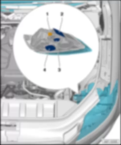
Fitting location
At headlight.
   
AUDI Q7 2011 Left headlight starter for gas discharge light J426 / right headlight starter for gas discharge light J427 https://portal-diagnostov.com/license.html
https://portal-diagnostov.com/license.html Automotive Electricians Portal FZCO Automotive Electricians Portal FZCO
Получить доступ ко всем электросхемам автомобиляDownload PDF file
1 -  14-pin connector -T14a-/14-pin connector -T14b-, black
2 -  Output module for left headlight -J667-/output module for right headlight -J668-
3 -  Left headlight starter for gas discharge light -J426-/right headlight starter for gas discharge light -J427-
4 -  Power output module 2 for left headlight -J892-/power output module 2 for right headlight -J893-

Back to overview → chapter.


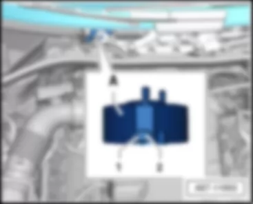
AUDI Q7 2011 Actuator for structure-borne sound R214

Actuator for structure-borne sound -R214-
Fitting location
   
Middle of plenum chamber.
A -  Actuator for structure-borne sound -R214-
Back to overview → chapter.


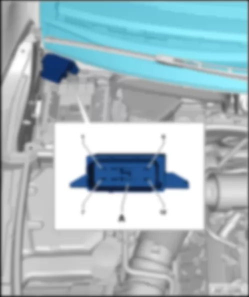
AUDI Q7 2011 Control unit for structure-borne sound J869

Control unit for structure-borne sound -J869-
Fitting location
On right in plenum chamber.
 
AUDI Q7 2011 Control unit for structure-borne sound J869 https://portal-diagnostov.com/license.html
https://portal-diagnostov.com/license.html Automotive Electricians Portal FZCO Automotive Electricians Portal FZCO
Получить доступ ко всем электросхемам автомобиляDownload PDF file
AUDI Q7 2011 Control unit for structure-borne sound J869 https://portal-diagnostov.com/license.html
https://portal-diagnostov.com/license.html Automotive Electricians Portal FZCO Automotive Electricians Portal FZCO
Получить доступ ко всем электросхемам автомобиляDownload PDF file
A -  Control unit for structure-borne sound -J869-

Back to overview → chapter.


AUDI Q7 2011 ABS control unit J104

ABS control unit -J104-
Fitting location
On right in plenum chamber.
   
AUDI Q7 2011 ABS control unit J104 https://portal-diagnostov.com/license.html
https://portal-diagnostov.com/license.html Automotive Electricians Portal FZCO Automotive Electricians Portal FZCO
Получить доступ ко всем электросхемам автомобиляDownload PDF file
A -  ABS control unit -J104-
1 -  47-pin connector -T47a-, black

Back to overview → chapter.


AUDI Q7 2011 Radiator fan control unit J293 / radiator fan control unit 2 J671

Radiator fan control unit -J293-/radiator fan control unit 2 -J671-
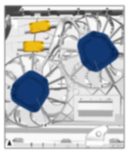
Fitting location:
at front of radiator.
   
AUDI Q7 2011 Radiator fan control unit J293 / radiator fan control unit 2 J671 https://portal-diagnostov.com/license.html
https://portal-diagnostov.com/license.html Automotive Electricians Portal FZCO Automotive Electricians Portal FZCO
Получить доступ ко всем электросхемам автомобиляDownload PDF file
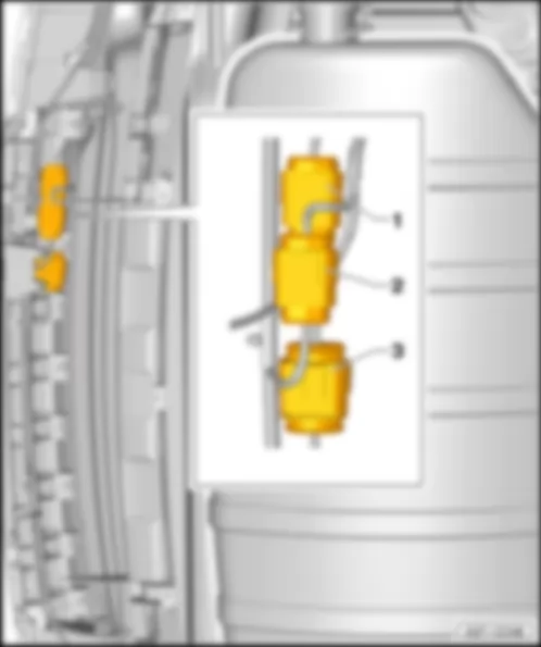
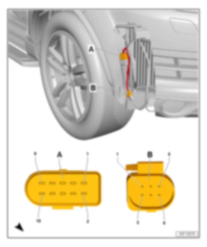
1 -  4-pin connector -T4-, black
2 -  4-pin connector -T4-, black
3 -  Radiator fan control unit -J293-/radiator fan -V7-
4 -  Radiator fan control unit 2 -J671-/radiator fan 2 -V177-

Back to overview → chapter.


AUDI Q7 2011 Steering column electronics control unit J527

Steering column electronics control unit -J527-
Fitting location
On steering column, at steering column switch.
Back
   
16-pin connector -T16a-, black
 
AUDI Q7 2011 Steering column electronics control unit J527 https://portal-diagnostov.com/license.html
https://portal-diagnostov.com/license.html Automotive Electricians Portal FZCO Automotive Electricians Portal FZCO
Получить доступ ко всем электросхемам автомобиляDownload PDF file
4-pin connector -T4a-, black
Back to overview → chapter.


AUDI Q7 2011 Power latching control unit J657

Power latching control unit -J657-
Fitting location:
Under rear end strip.
 
AUDI Q7 2011 Power latching control unit J657 https://portal-diagnostov.com/license.html
https://portal-diagnostov.com/license.html Automotive Electricians Portal FZCO Automotive Electricians Portal FZCO
Получить доступ ко всем электросхемам автомобиляDownload PDF file
AUDI Q7 2011 Power latching control unit J657 https://portal-diagnostov.com/license.html
https://portal-diagnostov.com/license.html Automotive Electricians Portal FZCO Automotive Electricians Portal FZCO
Получить доступ ко всем электросхемам автомобиляDownload PDF file
1 -  Power latching control unit -J657-
q   with rear lid lock motor -V120-, power latching system limit switch, luggage compartment unlocked -F332-, power latching system limit switch, luggage compartment locked -F333-
A -  5-pin connector -T5c-, black

Connector assignment for power latching control unit -J657-
   
-T5c- (A) Designation
1 Comfort system central control unit -J393-
2 Comfort system central control unit -J393-
3 Comfort system central control unit -J393-
4 Terminal 31
5 Comfort system central control unit -J393-

Back to overview → chapter.


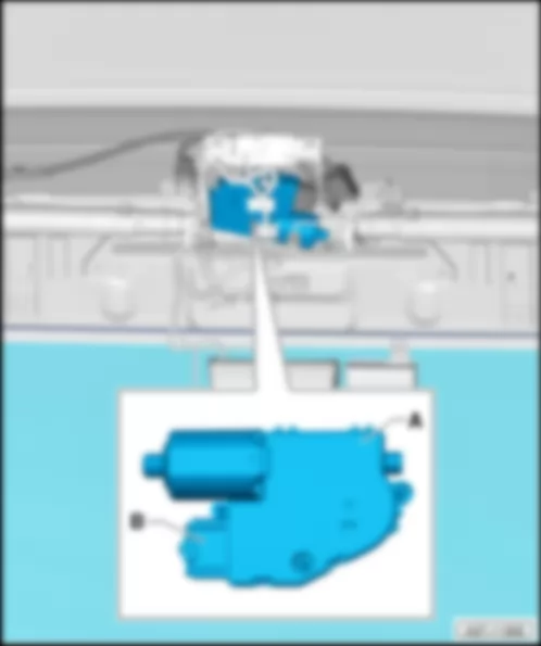
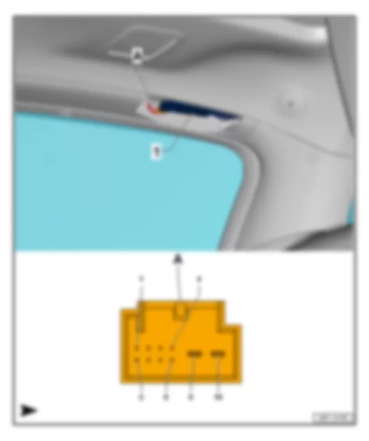
AUDI Q7 2011 Rear lid control unit J605

Rear lid control unit -J605-
Fitting location:
Under roof end trim, right.
   
AUDI Q7 2011 Rear lid control unit J605 https://portal-diagnostov.com/license.html
https://portal-diagnostov.com/license.html Automotive Electricians Portal FZCO Automotive Electricians Portal FZCO
Получить доступ ко всем электросхемам автомобиляDownload PDF file
1 -  Rear lid control unit -J605-
q   with motor in rear lid control unit -V375-
A -  8-pin connector -T8-

Connector assignment for rear lid control unit -J605-
   
-T8- (A) Designation   -T8- (A) Designation
1     5 Button to close rear lid in luggage compartment -E406-
2 Rear lid control unit 2 -J756-   6 Rear lid control unit 2 -J756-
3 Comfort CAN bus high   7 Comfort CAN bus low
4 Terminal 31   8 Terminal 30

Back to overview → chapter.


AUDI Q7 2011 Rear lid control unit 2 J756

Rear lid control unit 2 -J756-
Fitting location:
Under roof end trim, left.
   
AUDI Q7 2011 Rear lid control unit 2 J756 https://portal-diagnostov.com/license.html
https://portal-diagnostov.com/license.html Automotive Electricians Portal FZCO Automotive Electricians Portal FZCO
Получить доступ ко всем электросхемам автомобиляDownload PDF file
1 -  Rear lid control unit 2 -J756-
q   with motor in rear lid control unit 2 -V376-
A -  10-pin connector -T10-

Connector assignment for rear lid control unit 2 -J756-
   
-T10- (A) Designation   -T10- (A) Designation
1     6 Rear lid control unit -J605-
2 Rear lid control unit -J605-   7  
3 Rear lid contact switch for anti-theft alarm -F123-   8  
4     9 Terminal 31
5     10 Terminal 30

Back to overview → chapter.


AUDI Q7 2011 Rear fresh air blower control unit J391

Rear fresh air blower control unit -J391-
Fitting location:
Behind left luggage compartment trim.
   
AUDI Q7 2011 Rear fresh air blower control unit J391 https://portal-diagnostov.com/license.html
https://portal-diagnostov.com/license.html Automotive Electricians Portal FZCO Automotive Electricians Portal FZCO
Получить доступ ко всем электросхемам автомобиляDownload PDF file
1 -  Rear fresh air blower control unit -J391-
q   with rear fresh air blower -V80-, rear left vent temperature sender -G405-, rear right vent temperature sender -G406-, rear left temperature flap control motor-V313-, rear left temperature flap potentiometer-G391-, rear left air quantity flap control motor-V239-, rear left air quantity flap potentiometer-G389-, rear right air quantity flap control motor-V240-, rear right air quantity flap potentiometer-G390-, rear right temperature flap control motor-V314-, rear right temperature flap potentiometer-G392-
A -  12-pin connector -T12k-
B -  17-pin connector -T17h-

Back to overview → chapter.


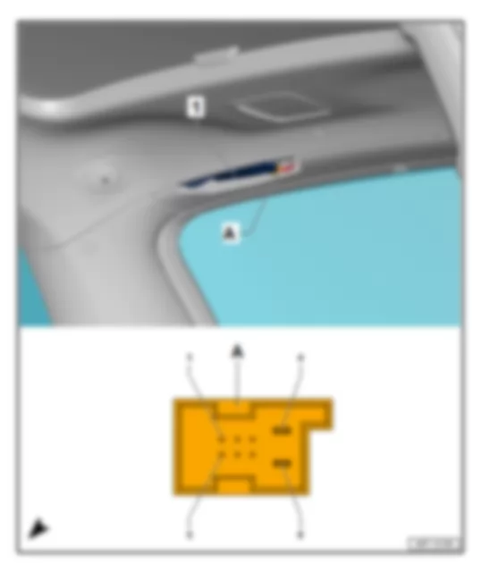
AUDI Q7 2011 Front interior light

Front interior light
Fitting location
In front of roof.
   
AUDI Q7 2011 Front interior light https://portal-diagnostov.com/license.html
https://portal-diagnostov.com/license.html Automotive Electricians Portal FZCO Automotive Electricians Portal FZCO
Получить доступ ко всем электросхемам автомобиляDownload PDF file
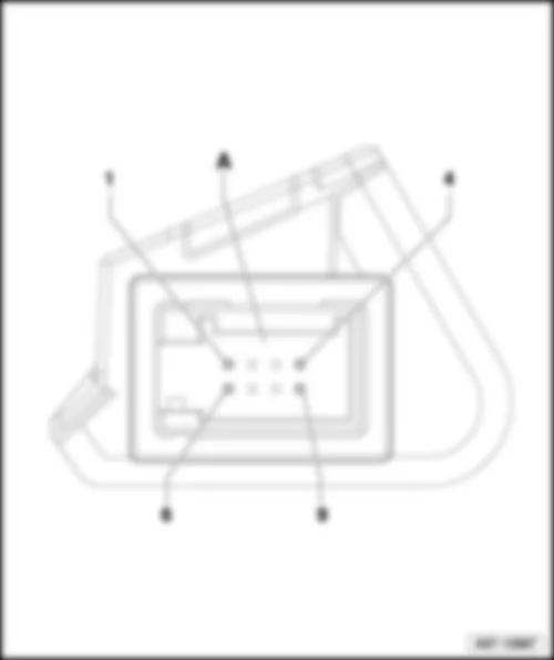
1 -  Front interior light
A -  16-pin connector -T16n-, black, sliding sunroof adjustment control unit -J245-
B -  12-pin connector -T12a-, black, front interior light
C -  6-pin, connector -T6ag-, black, sliding sunroof adjustment regulator -E139-
D -  6-pin, connector -T6x-, blue, microphone unit in front roof module -R164-

Back to overview → chapter.


AUDI Q7 2011 Fresh air blower control unit J126

Fresh air blower control unit -J126-
Fitting location
behind glove compartment.
   
AUDI Q7 2011 Fresh air blower control unit J126 https://portal-diagnostov.com/license.html
https://portal-diagnostov.com/license.html Automotive Electricians Portal FZCO Automotive Electricians Portal FZCO
Получить доступ ко всем электросхемам автомобиляDownload PDF file
1 -  Fresh air blower control unit -J126-
A -  17-pin connector -T17k-, black

Connector assignment for fresh air blower control unit -J126-
   
- T17k - (A) Designation   - T17k - (A) Designation
1 Terminal 30   10 Right temperature flap control motor -V159-
2 Terminal 31   11 Right temperature flap control motor -V159-
3 Terminal 30   12 Climatronic control unit -J255-
4     13 Climatronic control unit -J255-
5     14 Climatronic control unit -J255-
6 Climatronic control unit -J255-   15  
7 Potentiometer for right temperature flap control motor -G221-   16  
8 Potentiometer for indirect ventilation flap control motor -G330-   17  
9        

Back to overview → chapter.


AUDI Q7 2011 Overview of fuses

Overview of fuses
AUDI Q7 2011 Overview of fuses https://portal-diagnostov.com/license.html
https://portal-diagnostov.com/license.html Automotive Electricians Portal FZCO Automotive Electricians Portal FZCO
Получить доступ ко всем электросхемам автомобиляDownload PDF file
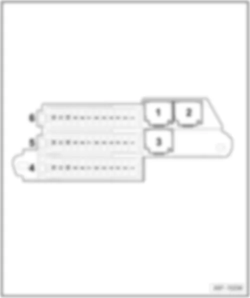
1 -  Fuses (SC) on fuse holder C
q   Fitting location and fuse assignment → chapter
2 -  relay and fuse carrier centre dash panel
q   Fitting location and fuse assignment → chapter
3 -  Fuses (SF) on fuse holder F
q   Fitting location and fuse assignment → chapter
4 -  Fuses (SD) on fuse holder D
q   Fitting location and fuse assignment → chapter
5 -  Fuses (SB) on fuse holder B
q   Fitting location and fuse assignment → chapter
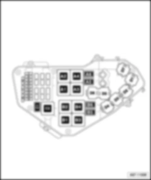
6 -  Relay and fuse carrier in electronics box engine compartment
q   Fitting location and fuse assignment → chapter
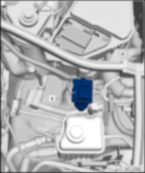
7 -  Terminal 30 wiring junction 2 -TV22-/slave start socket -U6-
q   Fitting location → chapter


AUDI Q7 2011 Fuses (SB) on fuse holder B

Fuses (SB) on fuse holder B
Fitting location
on left in dash panel
Fuse colours
40 A -  orange
30 A -  green
25 A -  white
20 A -  yellow
15 A -  blue
10 A -  red
7,5 A -  brown
5 A -  beige
3 A -  purple
Assignment
   
AUDI Q7 2011 Fuses (SB) on fuse holder B https://portal-diagnostov.com/license.html
https://portal-diagnostov.com/license.html Automotive Electricians Portal FZCO Automotive Electricians Portal FZCO
Получить доступ ко всем электросхемам автомобиляDownload PDF file
1 -  Fuse carrier ST1, red
q   Fuse assignment, left-hand drive models → chapter
q   Fuse assignment, right-hand drive models → chapter
q   Fuse assignment, left-hand drive models, from June 2009 → chapter
q   Fuse assignment, right-hand drive models, from June 2009 → chapter
2 -  Fuse carrier ST2, brown
q   Fuse assignment, left-hand drive models → chapter
q   Fuse assignment, right-hand drive models → chapter
q   Fuse assignment, left-hand drive models, from June 2009 → chapter
q   Fuse assignment, right-hand drive models, from June 2009 → chapter
3 -  Fuse carrier ST3, black
q   Fuse assignment, left-hand drive models → chapter
q   Fuse assignment, right-hand drive models → chapter
q   Fuse assignment, left-hand drive models, from June 2009 → chapter
q   Fuse assignment, right-hand drive models, from June 2009 → chapter
4 -  46-pin connector -T46a-, CAN disconnector
A -  Vacant
B -  Main fuse for optional equipment -S245-, 10 A
q   from June 2009
C -  Vacant
D -  Vacant

Back to overview → chapter.
   
Fuse assignment on fuse carrier ST1, red, left-hand drive models
No.   Current Flow Diagram designation Nominal value   Function/component Terminal
1 - Vacant      
2 - Vacant      
3 - Vacant      
4 - Fuse 4 on fuse holder B -SB4- 5 A - Tyre pressure monitor control unit -J502- 30
5 - Fuse 5 on fuse holder B -SB5- 20 A - Auxiliary heater control unit -J364- 30
6 - Fuse 6 on fuse holder B -SB6- 10 A - Driver seat lumbar support adjustment switch -E176- 30
7 - Fuse 7 on fuse holder B -SB7- 35 A - Driver door control unit -J386-
Driver side window regulator motor -V147-
Rear left door control unit -J388-
Rear left window regulator motor -V26-
30
8 - Fuse 8 on fuse holder B -SB8- 15 A - Driver door control unit -J386-
Rear left door control unit -J388-1) only
30
9 - Fuse 9 on fuse holder B -SB9- 5 A - Energy management control unit -J644-1) only 30
10 - Fuse 10 on fuse holder B -SB10- 30 A - Entry and start authorisation control unit -J518-
Entry​and​start​authorisation​switch -E415-
30
11 - Fuse 11 on fuse holder B -SB11- 10 A - Steering column electronics control unit -J527- 30
12 - Fuse 12 on fuse holder B -SB12- 5 A - Interior monitoring sensor -G273-
Alarm horn -H12-
30

  Note
1) up to May 2008
Back to overview → chapter.
   
Fuse assignment on fuse carrier ST2, brown, left-hand drive models
No.   Current Flow Diagram designation Nominal value   Function/component Terminal
1 - Vacant      
2 - Vacant      
3 - Vacant      
4 - Fuse 4 on fuse holder B -SB4- 30 A - Wiper motor control unit -J400-
Windscreen wiper motor -V-
30
5 - Fuse 5 on fuse holder B -SB5- 5 A - Light/rain sensor -G397- 30
6 - Fuse 6 on fuse holder B -SB6- 25 A - Dual tone horn relay -J4-
High tone horn -H2-
Low tone horn -H7-
30
7 - Fuse 7 on fuse holder B -SB7- 30 A - onboard supply control unit -J519- 30
8 - Fuse 8 on fuse holder B -SB8- 25 A - onboard supply control unit -J519- 30
9 - Fuse 9 on fuse holder B -SB9- 25 A - onboard supply control unit -J519- 30
10 - Fuse 10 on fuse holder B -SB10- 10 A - Control unit in dash panel insert -J285-
Data bus diagnostic interface -J533-
Display in dash panel insert -Y24-
30
11 - Fuse 11 on fuse holder B -SB11- 30 A - Headlight washer system relay -J39- 30
12 - Fuse 12 on fuse holder B -SB12- 10 A - 16-pin connector -T16-, diagnostic connector 30

Back to overview → chapter.
   
Fuse assignment on fuse carrier ST3, black, left-hand drive models
No.   Current Flow Diagram designation Nominal value   Function/component Terminal
1 - Fuse 1 on fuse holder B -SB1- 10 A - Left headlight 15
2 - Fuse 2 on fuse holder B -SB2- 5 A - Control unit for adaptive cruise control -J428-
Sensor heater for adaptive cruise control system -Z47-
15
3 - Fuse 3 on fuse holder B -SB3- 5 A   Direct sight Japan
display unit -J145-
Display unit button -E506-
15
4 - Fuse 4 on fuse holder B -SB4- 10 A - Lane departure warning
Lane departure warning control unit -J759-
Windscreen heater for lane departure warning -Z67-
15
5 - Fuse 5 on fuse holder B -SB5- 10 A
5 A1)
- Signal system control unit -J616-
Operating unit for special signals -E507-
Preparation for multimedia (9WM)1)
15
6 - Fuse 6 on fuse holder B -SB6- 5 A - Steering column electronics control unit -J527-
Entry and start authorisation control unit -J518-
Light switch -E1-
Comfort system central control unit -J393-
Trailer detector control unit -J345-
Tyre pressure monitor control unit -J502- (7K6)2)
15
7 - Fuse 7 on fuse holder B -SB7- 5 A - Oil level and oil temperature sender -G266- 15
8 - Fuse 8 on fuse holder B -SB8- 5 A - 16-pin connector -T16-, diagnostic connector 15
9 - Fuse 9 on fuse holder B -SB9- 5 A - Automatic anti-dazzle interior mirror -Y7- 15
10 - Fuse 10 on fuse holder B -SB10- 5 A - Garage door operation control unit -J530-
Garage door operating unit -E284-
15
11 - Fuse 11 on fuse holder B -SB11- 5 A - Data bus diagnostic interface -J533- 15
12 - Fuse 12 on fuse holder B -SB12- 5 A - Headlight range control regulator -E102-
Left headlight range control motor -V48-
Right headlight range control motor -V49-
15

  Note
t  1) from November 2007
t  2) from June 2008
Back to overview → chapter.
   
Fuse assignment on fuse carrier ST1, red, right-hand drive models
No.   Current Flow Diagram designation Nominal value   Function/component Terminal
1 - Vacant      
2 - Vacant      
3 - Vacant      
4 - Fuse 4 on fuse holder B -SB4- 5 A - Tyre pressure monitor control unit -J502- 30
5 - Fuse 5 on fuse holder B -SB5- 20 A - Auxiliary heater control unit -J364- 30
6 - Fuse 6 on fuse holder B -SB6- 10 A - Front passenger seat lumbar support adjustment switch -E177- 30
7 - Fuse 7 on fuse holder B -SB7- 35 A - Front passenger door control unit -J387-
Rear right window regulator motor -V27-
Front passenger side window regulator motor -V148-
30
8 - Fuse 8 on fuse holder B -SB8- 15 A - Front passenger door control unit -J387-
Rear right door control unit -J389-
30
9 - Fuse 9 on fuse holder B -SB9- 5 A - Energy management control unit -J644-1) only 30
10 - Fuse 10 on fuse holder B -SB10- 5 A - Media player in position 1 -R118-
Media player in position 2 -R119-
CD changer -R41-
MiniDisc player -R153-
Video recorder and DVD player -R129-
Connection for external audio sources -R199-2) only
30
11 - Fuse 11 on fuse holder B -SB11- 10 A - Rear Climatronic operating and display unit -E265-
Rear fresh air blower control unit -J391-
30
12 - Fuse 12 on fuse holder B -SB12- 5 A - Comfort system central control unit -J393- 30

  Note
t  1) up to May 2008
t  2) from November 2006
Back to overview → chapter.
   
Fuse assignment on fuse carrier ST2, brown, right-hand drive models
No.   Current Flow Diagram designation Nominal value   Function/component Terminal
1 - Vacant      
2 - Vacant      
3 - Vacant      
4 - Fuse 4 on fuse holder B -SB4- 30 A - Wiper motor control unit -J400-
Windscreen wiper motor -V-
30
5 - Fuse 5 on fuse holder B -SB5- 5 A - Light/rain sensor -G397- 30
6 - Fuse 6 on fuse holder B -SB6- 25 A - High tone horn -H2-
Low tone horn -H7-
Dual tone horn relay -J4-
30
7   Vacant      
8 - Fuse 8 on fuse holder B -SB8- 20 A - Cigarette lighter -U1- 30
9 - Fuse 9 on fuse holder B -SB9- 25 A - 12 V socket -U5-
12 V socket 2 -U18-
30
10 - Fuse 10 on fuse holder B -SB10- 10 A - Climatronic control unit -J255-
Fresh air blower control unit -J126-
30
11 - Fuse 11 on fuse holder B -SB11- 30 A - Headlight washer system relay -J39- 30
12 - Fuse 12 on fuse holder B -SB12- 10 A - 16-pin connector -T16-, diagnostic connector 30

Back to overview → chapter.
   
Fuse assignment on fuse carrier ST3, black, right-hand drive models
No.   Current Flow Diagram designation Nominal value   Function/component Terminal
1 - Fuse 1 on fuse holder B -SB1- 10 A - Left headlight 15
2 - Fuse 2 on fuse holder B -SB2- 5 A - Control unit for adaptive cruise control -J428-
Sensor heater for adaptive cruise control system -Z47-
15
3 - Fuse 3 on fuse holder B -SB3- 5 A - Direct sight Japan
display unit -J145-
Display unit button -E506-
15
4 - Fuse 4 on fuse holder B -SB4- 10 A - Lane departure warning control unit -J759-
Windscreen heater for lane departure warning -Z67-
15
5 - Fuse 5 on fuse holder B -SB5- 5 A - Preparation for multimedia (9WM)1) 15
6 - Fuse 6 on fuse holder B -SB6- 5 A - Heated bench seat cushion for rear left seat -Z10-
Heated backrest for rear left seat -Z11-
Heated bench seat cushion for rear right seat -Z12-
Heated backrest for rear right seat -Z13-
15
7 - Fuse 7 on fuse holder B -SB7- 5 A   Oil level and oil temperature sender -G266- 15
8 - Fuse 8 on fuse holder B -SB8- 5 A - 16-pin connector -T16-, diagnostic connector 15
9 - Fuse 9 on fuse holder B -SB9- 5 A - Automatic anti-dazzle interior mirror -Y7- 15
10 - Fuse 10 on fuse holder B -SB10- 5 A - Garage door operation control unit -J530-
Garage door operating unit -E284-
15
11 - Fuse 11 on fuse holder B -SB11- 5 A - Airbag control unit -J234- 15
12 - Fuse 12 on fuse holder B -SB12- 5 A - Air quality sensor -G238-
Rear Climatronic operating and display unit -E265-
Climatronic control unit -J255-
15

  Note
1) from November 2007
Back to overview → chapter.
   
Fuses in fuse carrier ST1, red, left-hand drive models, from June 2009
No.   Current Flow Diagram designation Nominal value   Function/component Terminal
1 - Fuse 1 on fuse holder B -SB1- 5 A - Voltage stabiliser -J532-1) only 50
2 - Fuse 2 on fuse holder B -SB2- 5 A - Relay for automatic anti-dazzle interior mirror -J910-1) only 30
3 - Fuse 3 on fuse holder B -SB3- 7.5 A - Control unit for information electronics 1 -J794-1) only 30
4 - Fuse 4 on fuse holder B -SB4- 5 A - Tyre pressure monitor control unit -J502-2) only 30
5 - Fuse 5 on fuse holder B -SB5- 20 A - Auxiliary heater control unit -J364- 30
6 - Fuse 6 on fuse holder B -SB6- 10 A - Driver seat lumbar support adjustment switch -E176- 30
7 - Fuse 7 on fuse holder B -SB7- 35 A - Driver door control unit -J386-
Driver side window regulator motor -V147-
Rear left door control unit -J388-
Rear left window regulator motor -V26-
30
8 - Fuse 8 on fuse holder B -SB8- 15 A - Driver door control unit -J386- 30
9 - Fuse 9 on fuse holder B -SB9- 5 A - Tyre pressure monitor control unit -J502-1) only 30
10 - Fuse 10 on fuse holder B -SB10- 30 A - Entry and start authorisation control unit -J518-
Entry​and​start​authorisation​switch -E415-
30
11 - Fuse 11 on fuse holder B -SB11- 10 A - Steering column electronics control unit -J527- 30
12 - Fuse 12 on fuse holder B -SB12- 5 A - Interior monitoring sensor -G273-
Alarm horn -H12-
30

  Note
t  1) from June 2010
t  2) up to May 2010
Back to overview → chapter.
   
Fuse assignment on fuse carrier ST2, brown, left-hand drive models, from June 2009
No.   Current Flow Diagram designation Nominal value   Function/component Terminal
1 - Vacant      
2 - Vacant      
3 - Fuse 3 on fuse holder B -SB3- 15 A - Front left seat ventilation control unit -J800- 30
4 - Fuse 4 on fuse holder B -SB4- 30 A - Wiper motor control unit -J400-
Windscreen wiper motor -V-
30
5 - Fuse 5 on fuse holder B -SB5- 5 A - Light/rain sensor -G397- 30
6 - Fuse 6 on fuse holder B -SB6- 25 A - Dual tone horn relay -J4-
High tone horn -H2-
Low tone horn -H7-
30
7 - Fuse 7 on fuse holder B -SB7- 30 A - onboard supply control unit -J519- 30
8 - Fuse 8 on fuse holder B -SB8- 25 A - onboard supply control unit -J519- 30
9 - Fuse 9 on fuse holder B -SB9- 25 A - onboard supply control unit -J519- 30
10 - Fuse 10 on fuse holder B -SB10- 10 A - Control unit in dash panel insert -J285-1)
Diagnostic interface for data bus -J533-
Display in dash panel insert -Y24-1) only
30
11 - Fuse 11 on fuse holder B -SB11- 30 A - Headlight washer system relay -J39- 30
12 - Fuse 12 on fuse holder B -SB12- 10 A - 16-pin connector -T16-, diagnostic connector 30

  Note
1) up to May 2010
Back to overview → chapter.
   
Fuse assignment on fuse carrier ST3, black, left-hand drive models, from June 2009
No.   Current Flow Diagram designation Nominal value   Function/component Terminal
1 - Fuse 1 on fuse holder B -SB1- 10 A - Left headlight 15
2 - Fuse 2 on fuse holder B -SB2- 5 A - Control unit for adaptive cruise control -J428-
Sensor heater for adaptive cruise control system -Z47-
15
3 - Fuse 3 on fuse holder B -SB3- 5 A   Direct sight Japan
display unit -J145-
Display unit button -E506-
Coolant shut-off valve relay -J541-1)
Heater coolant shut-off valve -N279-1) only
15
4 - Fuse 4 on fuse holder B -SB4- 10 A - Lane departure warning
Lane departure warning control unit -J759-
Windscreen heater for lane departure warning -Z67-
15
5 - Fuse 5 on fuse holder B -SB5- 5 A - Preparation for multimedia (9WM) 15
6 - Fuse 6 on fuse holder B -SB6- 5 A - Steering column electronics control unit -J527-
Entry and start authorisation control unit -J518-
Light switch -E1-
Comfort system central control unit -J393-
Trailer detector control unit -J345-
Tyre pressure monitor control unit -J502- (7K6)
15
7 - Fuse 7 on fuse holder B -SB7- 5 A - Oil level and oil temperature sender -G266- 15
8 - Fuse 8 on fuse holder B -SB8- 5 A - 16-pin connector -T16- (diagnostic connector) 15
9 - Fuse 9 on fuse holder B -SB9- 5 A - Automatic anti-dazzle interior mirror -Y7- 15
10 - Fuse 10 on fuse holder B -SB10- 5 A - Garage door operation control unit -J530-
Garage door operating unit -E284-
15
11 - Fuse 11 on fuse holder B -SB11- 5 A - Data bus diagnostic interface -J533- 15
12 - Fuse 12 on fuse holder B -SB12- 5 A - Headlight range control regulator -E102-
Left headlight range control motor -V48-
Right headlight range control motor -V49-
15

  Note
1) only for models with 6-cylinder diesel engine, generation 2
Back to overview → chapter.
   
Fuse assignment on fuse carrier ST1, red, right-hand drive models, from June 2009
No.   Current Flow Diagram designation Nominal value   Function/component Terminal
1 - Fuse 1 on fuse holder B -SB1- 5 A - Voltage stabiliser -J532-1) only 30
2 - Fuse 2 on fuse holder B -SB2- 5 A - Relay for automatic anti-dazzle interior mirror -J910-1) only 30
3 - Fuse 3 on fuse holder B -SB3- 7.5 A - Control unit for information electronics 1 -J794-1) only 30
4 - Fuse 4 on fuse holder B -SB4- 5 A - Tyre pressure monitor control unit -J502-2) only 30
5 - Fuse 5 on fuse holder B -SB5- 20 A - Auxiliary heater control unit -J364- 30
6 - Fuse 6 on fuse holder B -SB6- 10 A - Front passenger seat lumbar support adjustment switch -E177- 30
7 - Fuse 7 on fuse holder B -SB7- 35 A - Front passenger door control unit -J387-
Rear right window regulator motor -V27-
Front passenger side window regulator motor -V148-
30
8 - Fuse 8 on fuse holder B -SB8- 15 A - Front passenger door control unit -J387-
Rear right door control unit -J389-
30
9 - Fuse 9 on fuse holder B -SB9- 5 A - Tyre pressure monitor control unit -J502-1) only 30
10 - Fuse 10 on fuse holder B -SB10- 5 A - CD changer -R41-2)
DVD player -R7-2) only
30
11 - Fuse 11 on fuse holder B -SB11- 10 A - Rear Climatronic operating and display unit -E265-
Rear fresh air blower control unit -J391-
30
12 - Fuse 12 on fuse holder B -SB12- 5 A - Comfort system central control unit -J393- 30

  Note
t  1) from June 2010
t  2) up to May 2010
Back to overview → chapter.
   
Fuse assignment on fuse carrier ST2, brown, right-hand drive models, from June 2009
No.   Current Flow Diagram designation Nominal value   Function/component Terminal
1 - Vacant      
2 - Vacant      
3 - Fuse 3 on fuse holder B -SB3- 15 A - Front left seat ventilation control unit -J800- 30
4 - Fuse 4 on fuse holder B -SB4- 30 A - Wiper motor control unit -J400-
Windscreen wiper motor -V-
30
5 - Fuse 5 on fuse holder B -SB5- 5 A - Light/rain sensor -G397- 30
6 - Fuse 6 on fuse holder B -SB6- 25 A - High tone horn -H2-
Low tone horn -H7-
Dual tone horn relay -J4-
30
7 - Fuse 7 on fuse holder B -SB7- 25 A - 12 V socket 3 -U19-1)
12 V socket 4 -U20-1) only
30
8 - Fuse 8 on fuse holder B -SB8- 20 A - Cigarette lighter -U1- 30
9 - Fuse 9 on fuse holder B -SB9- 25 A - 12 V socket -U5-
12 V socket 2 -U18-
30
10 - Fuse 10 on fuse holder B -SB10- 10 A - Climatronic control unit -J255-
Fresh air blower control unit -J126-
30
11 - Fuse 11 on fuse holder B -SB11- 30 A - Headlight washer system relay -J39- 30
12 - Fuse 12 on fuse holder B -SB12- 10 A - 16-pin connector -T16-, diagnostic connector 30

  Note
1) from June 2010
Back to overview → chapter.
   
Fuse assignment on fuse carrier ST3, black, right-hand drive models, from June 2009
No.   Current Flow Diagram designation Nominal value   Function/component Terminal
1 - Fuse 1 on fuse holder B -SB1- 10 A - Left headlight 15
2 - Fuse 2 on fuse holder B -SB2- 5 A - Control unit for adaptive cruise control -J428-
Sensor heater for adaptive cruise control system -Z47-
15
3 - Fuse 3 on fuse holder B -SB3- 5 A - Direct sight Japan
display unit -J145-
Display unit button -E506-
Coolant shut-off valve relay -J541-1)
Heater coolant shut-off valve -N279-1) only
15
4 - Fuse 4 on fuse holder B -SB4- 10 A - Lane departure warning control unit -J759-
Windscreen heater for lane departure warning -Z67-
15
5 - Fuse 5 on fuse holder B -SB5- 5 A - Preparation for multimedia (9WM) 15
6 - Fuse 6 on fuse holder B -SB6- 5 A - Heated bench seat cushion for rear left seat -Z10-
Heated backrest for rear left seat -Z11-
Heated bench seat cushion for rear right seat -Z12-
Heated backrest for rear right seat -Z13-
15
7 - Fuse 7 on fuse holder B -SB7- 5 A   Oil level and oil temperature sender -G266- 15
8 - Fuse 8 on fuse holder B -SB8- 5 A - 16-pin connector -T16-, diagnostic connector 15
9 - Fuse 9 on fuse holder B -SB9- 5 A - Automatic anti-dazzle interior mirror -Y7- 15
10 - Fuse 10 on fuse holder B -SB10- 5 A - Garage door operation control unit -J530-
Garage door operating unit -E284-
15
11 - Fuse 11 on fuse holder B -SB11- 5 A - Airbag control unit -J234- 15
12 - Fuse 12 on fuse holder B -SB12- 5 A - Air quality sensor -G238-
Rear Climatronic operating and display unit -E265-
Climatronic control unit -J255-
15

  Note
1) only for models with 6-cylinder diesel engine, generation 2
Back to overview → chapter.


AUDI Q7 2011 Fuses (SC) on fuse holder C

Fuses (SC) on fuse holder C
Fitting location
on right in dash panel
Fuse colours
40 A -  orange
30 A -  green
25 A -  white
20 A -  yellow
15 A -  blue
10 A -  red
7,5 A -  brown
5 A -  beige
Assignment
   
AUDI Q7 2011 Fuses (SC) on fuse holder C https://portal-diagnostov.com/license.html
https://portal-diagnostov.com/license.html Automotive Electricians Portal FZCO Automotive Electricians Portal FZCO
Получить доступ ко всем электросхемам автомобиляDownload PDF file
1 -  Fuse carrier ST1, black
q   Fuse assignment, left-hand drive models → chapter
q   Fuse assignment, right-hand drive models → chapter
q   Fuse assignment, left-hand drive models, from June 2009 → chapter
q   Fuse assignment, right-hand drive models, from June 2009 → chapter
2 -  Fuse carrier ST2, brown
q   Fuse assignment, left-hand drive models → chapter
q   Fuse assignment, right-hand drive models → chapter
q   Fuse assignment, left-hand drive models, from June 2009 → chapter
q   Fuse assignment, right-hand drive models, from June 2009 → chapter
3 -  Fuse carrier ST3, red
q   Fuse assignment, left-hand drive models → chapter
q   Fuse assignment, right-hand drive models → chapter
q   Fuse assignment, left-hand drive models, from June 2009 → chapter
q   Fuse assignment, right-hand drive models, from June 2009 → chapter
4 -  46-pin connector -T46b-, CAN disconnector
A -  Fuse for control unit for structure-borne sound -S348-, 5 A
B -  Cool box fuse -S340-, 5 A
q   from June 2008
C -  Vacant
D -  Vacant

Back to overview → chapter.
   
Fuse assignment on fuse carrier ST1, black, left-hand drive models
No.   Current Flow Diagram designation Nominal value   Function/component Terminal
1 - Fuse 1 on fuse holder C -SC1- 20 A - Heated bench seat cushion for rear left seat -Z10-
Heated backrest for rear left seat -Z11-
Heated bench seat cushion for rear right seat -Z12-
Heated backrest for rear right seat -Z13-
30
2 - Fuse 2 on fuse holder C -SC2- 10 A - Automatic gearbox control unit -J217- (0AT) 30
  5 A - Automatic gearbox control unit -J217- (09D) 30
3 - Fuse 3 on fuse holder C -SC3- 30 A - Heated seat cushion for front left seat -Z45-
Heated seat cushion for front right seat -Z46-
30
4 - Fuse 4 on fuse holder C -SC4- 20 A - ABS control unit -J104- 30
5 - Fuse 5 on fuse holder C -SC5- 15 A - Front passenger door control unit -J387-
Rear right door control unit -J389-1) only
30
6 - Fuse 6 on fuse holder C -SC6- 25 A - 12 V socket 3 -U19-
12 V socket 4 -U20-
30
7 - Fuse 7 on fuse holder C -SC7- 10 A - Front passenger seat lumbar support adjustment switch -E177- 30
8 - Fuse 8 on fuse holder C -SC8- 20 A - Cigarette lighter -U1- 30
9 - Fuse 9 on fuse holder C -SC9- 25 A - 12 V socket -U5-
12 V socket 2 -U18-
30
10 - Fuse 10 on fuse holder C -SC10- 10 A - Climatronic control unit -J255-
Fresh air blower control unit -J126-
30
11 - Fuse 11 on fuse holder C -SC11- 5 A - Brake light switch -F-1)
Brake pedal switch -F47-1)
ABS control unit -J104-1) only
30
12 - Fuse 12 on fuse holder C -SC12- 15 A - Onboard supply control unit 2 -J520- 30

  Note
1) up to May 2008
Back to overview → chapter.
   
Fuse assignment on fuse carrier ST2, brown, left-hand drive models
No.   Current Flow Diagram designation Nominal value   Function/component Terminal
1 - Fuse 1 on fuse holder C -SC1- 10 A - Right headlight 15
2 - Fuse 2 on fuse holder C -SC2- 5 A - Adaptive suspension control unit -J197- 15
3 - Fuse 3 on fuse holder C -SC3- 5 A - Preparation for mobile telephone (9ZD) 15
4 - Fuse 4 on fuse holder C -SC4- 5 A - Lane change assist control unit -J769-
Lane change assist control unit 2 -J770-
15
5 - Fuse 5 on fuse holder C -SC5- 5 A - Brake light suppression relay -J508-
Clutch pedal switch -F36-
15
6 - Fuse 6 on fuse holder C -SC6- 5 A - Automatic gearbox control unit -J217- (0AT) 15
  20 A - Automatic gearbox control unit -J217- (09D) 15
7 - Fuse 7 on fuse holder C -SC7- 5 A - ABS control unit -J104- 15
8 - Fuse 8 on fuse holder C -SC8- 5 A - Multifunction switch -F125-
Tiptronic switch -F189-
Selector lever sensors control unit -J587-
15
9 - Fuse 9 on fuse holder C -SC9- 5 A - Control unit for parking aid -J446- 15
10 - Fuse 10 on fuse holder C -SC10- 5 A - Airbag control unit -J234- 15
11 - Fuse 11 on fuse holder C -SC11- 5 A - Heated rear left seat switch with regulator -E128-
Heated rear right seat switch with regulator -E129-
15
12 - Fuse 12 on fuse holder C -SC12- 5 A - Air quality sensor -G238-
Rear Climatronic operating and display unit -E265-
Climatronic control unit -J255-
15

Back to overview → chapter.
   
Fuse assignment on fuse carrier ST3, red, left-hand drive models
No.   Current Flow Diagram designation Nominal value   Function/component Terminal
1 - Fuse 1 on fuse holder C -SC1- 15 A - Rear window wiper motor -V12-1)
Cool box -J698-2) only
75
2 - Fuse 2 on fuse holder C -SC2- 5 A - Left washer jet heater element -Z20-
Right washer jet heater element -Z21-
75
3 - Vacant -      
4 - Vacant -      
5 - Fuse 5 on fuse holder C -SC5- 5 A - Telephone transmitter and receiver unit -R36- 30
6 - Fuse 6 on fuse holder C -SC6- 15 A - Control unit for front information display and operating unit -J523-
Aerial amplifier -R24-
30
  7.5 A - Control unit for front information display and operating unit -J523- 30
7 - Fuse 7 on fuse holder C -SC7- 20 A - Sliding sunroof adjustment control unit -J245- 30
8 - Fuse 8 on fuse holder C -SC8- 20 A - Rear sliding sunroof control unit -J392- 30
9 - Fuse 9 on fuse holder C -SC9- 20 A - Sunroof roller blind control unit -J394- 30
10 - Fuse 10 on fuse holder C -SC10- 5 A - Media player in position 1 -R118-
Media player in position 2 -R119-
CD changer -R41-
MiniDisc player -R153-
Video recorder and DVD player -R129-
Connection for external audio sources -R199-3) only
30
11 - Fuse 11 on fuse holder C -SC11- 35 A - Front passenger side window regulator motor -V148-
Rear right window regulator motor -V27-
30
12 - Fuse 12 on fuse holder C -SC12- 10 A - Rear Climatronic operating and display unit -E265-
Rear fresh air blower control unit -J391-
30

  Note
t  1) up to May 2007
t  2) from June 2008
t  3) from November 2006
Back to overview → chapter.
   
Fuse assignment on fuse carrier ST1, black, right-hand drive models
No.   Current Flow Diagram designation Nominal value   Function/component Terminal
1 - Fuse 1 on fuse holder C -SC1- 20 A - Heated bench seat cushion for rear left seat -Z10-
Heated backrest for rear left seat -Z11-
Heated bench seat cushion for rear right seat -Z12-
Heated backrest for rear right seat -Z13-
30
2 - Fuse 2 on fuse holder C -SC2- 10 A - Automatic gearbox control unit -J217- (0AT) 30
  5 A - Automatic gearbox control unit -J217- (09D) 30
3 - Fuse 3 on fuse holder C -SC3- 30 A - Heated seat cushion for front left seat -Z45-
Heated seat cushion for front right seat -Z46-
30
4 - Fuse 4 on fuse holder C -SC4- 20 A - ABS control unit -J104- 30
5 - Fuse 5 on fuse holder C -SC5- 15 A - Driver door control unit -J386-
Rear left door control unit -J388-
30
6   Fuse 6 on fuse holder C -SC6- 25 A - 12 V socket 3 -U19-
12 V socket 4 -U20-
30
7 - Fuse 7 on fuse holder C -SC7- 10 A - Driver seat lumbar support adjustment switch -E176- 30
8 - Fuse 8 on fuse holder C -SC8- 25 A - onboard supply control unit -J519- 30
9 - Fuse 9 on fuse holder C -SC9- 25 A - onboard supply control unit -J519- 30
10 - Fuse 10 on fuse holder C -SC10- 10 A - Control unit in dash panel insert -J285- 30
11 - Fuse 11 on fuse holder C -SC11- 5 A - Brake light switch -F-1)
Brake pedal switch -F47-1)
ABS control unit -J104-1) only
30
12 - Fuse 12 on fuse holder C -SC12- 15 A - Onboard supply control unit 2 -J520- 30

  Note
1) up to May 2008
Back to overview → chapter.
   
Fuse assignment on fuse carrier ST2, brown, right-hand drive models
No.   Current Flow Diagram designation Nominal value   Function/component Terminal
1 - Fuse 1 on fuse holder C -SC1- 10 A - Right headlight 15
2 - Fuse 2 on fuse holder C -SC2- 5 A - Adaptive suspension control unit -J197- 15
3 - Fuse 3 on fuse holder C -SC3- 5 A - Preparation for mobile telephone (9ZD) 15
4 - Fuse 4 on fuse holder C -SC4- 5 A - Lane change assist control unit -J769-
Lane change assist control unit 2 -J770-
15
5 - Fuse 5 on fuse holder C -SC5- 5 A - Brake light suppression relay -J508-
Clutch pedal switch -F36-
15
6 - Fuse 6 on fuse holder C -SC6- 5 A - Automatic gearbox control unit -J217- (0AT) 15
  20 A - Automatic gearbox control unit -J217- (09D) 15
7 - Fuse 7 on fuse holder C -SC7- 5 A - ABS control unit -J104- 15
8 - Fuse 8 on fuse holder C -SC8- 5 A - Multifunction switch -F125-
Tiptronic switch -F189-
Selector lever sensors control unit -J587-
15
9 - Fuse 9 on fuse holder C -SC9- 5 A - Control unit for parking aid -J446- 15
10 - Fuse 10 on fuse holder C -SC10- 5 A - Data bus diagnostic interface -J533- 15
11 - Fuse 11 on fuse holder C -SC11- 5 A - Steering column electronics control unit -J527-
Entry and start authorisation control unit -J518-
Light switch -E1-
Comfort system central control unit -J393-
Trailer detector control unit -J345-
15
12 - Fuse 12 on fuse holder C -SC12- 5 A - Headlight range control regulator -E102-
Left headlight range control motor -V48-
Right headlight range control motor -V49-
15

Back to overview → chapter.
   
Fuse assignment on fuse carrier ST3, red, right-hand drive models
No.   Current Flow Diagram designation Nominal value   Function/component Terminal
1 - Fuse 1 on fuse holder C -SC1- 15 A - Rear window wiper motor -V12-1)
Cool box -J698-2) only
75
2 - Fuse 2 on fuse holder C -SC2- 5 A - Left washer jet heater element -Z20-1)
Right washer jet heater element -Z21-1) only
75
3 - Fuse 3 on fuse holder C -SC3- 30 A - onboard supply control unit -J519- 30
4 - Vacant -      
5 - Fuse 5 on fuse holder C -SC5- 5 A - Telephone transmitter and receiver unit -R36- 30
6 - Fuse 6 on fuse holder C -SC6- 15 A - Control unit for front information display and operating unit -J523-
Aerial amplifier -R24-
30
  7.5 A - Control unit for front information display and operating unit -J523- 30
7 - Fuse 7 on fuse holder C -SC7- 20 A - Sliding sunroof adjustment control unit -J245- 30
8 - Fuse 8 on fuse holder C -SC8- 20 A - Rear sliding sunroof control unit -J392- 30
9 - Fuse 9 on fuse holder C -SC9- 20 A - Sunroof roller blind control unit -J394- 30
10 - Fuse 10 on fuse holder C -SC10- 30 A - Entry and start authorisation control unit -J518-
Entry​and​start​authorisation​switch -E415-
30
11 - Fuse 11 on fuse holder C -SC11- 35 A - Driver door control unit -J386-
Driver side window regulator motor -V147-
Rear left door control unit -J388-
Rear left window regulator motor -V26-
30
12 - Fuse 12 on fuse holder C -SC12- 10 A - Steering column electronics control unit -J527- 30

  Note
t  1) up to May 2007
t  2) from June 2008
Back to overview → chapter.
   
Fuse assignment on fuse carrier ST1, black, left-hand drive models, from June 2009
No.   Current Flow Diagram designation Nominal value   Function/component Terminal
1 - Fuse 1 on fuse holder C -SC1- 20 A - Heated bench seat cushion for rear left seat -Z10-
Heated backrest for rear left seat -Z11-
Heated bench seat cushion for rear right seat -Z12-
Heated backrest for rear right seat -Z13-
30
2 - Fuse 2 on fuse holder C -SC2- 10 A - Automatic gearbox control unit -J217- (0AT) 1) 30
  5 A - Automatic gearbox control unit -J217- (09D) 1)
Aerial amplifier for mobile telephone -R86-2)
Chip card reader control unit -J676-2)
Telephone bracket -R126-2) only
30
3 - Fuse 3 on fuse holder C -SC3- 30 A

15 A
- Heated seat cushion for front left seat -Z45-
Heated seat cushion for front right seat -Z46-
Front right seat ventilation control unit -J799-
30
4 - Fuse 4 on fuse holder C -SC4- 20 A - ABS control unit -J104- 30
5 - Fuse 5 on fuse holder C -SC5- 15 A - Front passenger door control unit -J387- 30
6 - Fuse 6 on fuse holder C -SC6- 25 A - 12 V socket 3 -U19-
12 V socket 4 -U20-
87
7 - Fuse 7 on fuse holder C -SC7- 10 A - Front passenger seat lumbar support adjustment switch -E177- 30
8 - Fuse 8 on fuse holder C -SC8- 20 A - Cigarette lighter -U1- 87
9 - Fuse 9 on fuse holder C -SC9- 25 A - 12 V socket -U5-
12 V socket 2 -U18-
87
10 - Fuse 10 on fuse holder C -SC10- 10 A - Climatronic control unit -J255-
Fresh air blower control unit -J126-
30
11 - Fuse 11 on fuse holder C -SC11- 15 A - Refrigerator box -J698-2) only 30
12 - Fuse 12 on fuse holder C -SC12- 15 A - Onboard supply control unit 2 -J520- 30

  Note
t  1) up to May 2010
t  2) from June 2010
Back to overview → chapter.
   
Fuse assignment on fuse carrier ST2, brown, left-hand drive models, from June 2009
No.   Current Flow Diagram designation Nominal value   Function/component Terminal
1 - Fuse 1 on fuse holder C -SC1- 10 A - Right headlight 15
2 - Fuse 2 on fuse holder C -SC2- 5 A - Adaptive suspension control unit -J197- 15
3 - Fuse 3 on fuse holder C -SC3- 5 A - Preparation for mobile telephone (9ZD) 15
4 - Fuse 4 on fuse holder C -SC4- 5 A - Lane change assist control unit -J769-
Lane change assist control unit 2 -J770-
15
5 - Fuse 5 on fuse holder C -SC5- 5 A - Brake light suppression relay -J508- 15
6   Fuse 6 on fuse holder C -SC6- 5 A - Automatic gearbox control unit -J217- 15
  20 A - Automatic gearbox control unit -J217- (09D) 15
7 - Fuse 7 on fuse holder C -SC7- 5 A - ABS control unit -J104- 15
8 - Fuse 8 on fuse holder C -SC8- 5 A - Multifunction switch -F125-
Tiptronic switch -F189-
Selector lever sensors control unit -J587-
15
9 - Fuse 9 on fuse holder C -SC9- 5 A - Control unit for parking aid -J446-
Control unit for overhead view camera -J928-1) only
15
10 - Fuse 10 on fuse holder C -SC10- 5 A - Airbag control unit -J234- 15
11 - Fuse 11 on fuse holder C -SC11- 5 A - Heated rear left seat switch with regulator -E128-
Heated rear right seat switch with regulator -E129-
15
12 - Fuse 12 on fuse holder C -SC12- 5 A - Air quality sensor -G238-
Rear Climatronic operating and display unit -E265-
Climatronic control unit -J255-
15

  Note
1) from June 2012
Back to overview → chapter.
   
Fuse assignment on fuse carrier ST3, red, left-hand drive models, from June 2009
No.   Current Flow Diagram designation Nominal value   Function/component Terminal
1 - Fuse 1 on fuse holder C -SC1- 15 A 1)
10 A 2)
- Refrigerator box -J698-1)
Control unit in dash panel insert -J285-2) only
30
2 - Fuse 2 on fuse holder C -SC2- 5 A - Reversing camera system control unit -J772-2) only 30
3 - Fuse 3 on fuse holder C -SC3- 5 A - DVD player -R7-2) 3)
CD changer -R41-2) 3)
30
4 - Fuse 4 on fuse holder C -SC4- 5 A - Display unit for front information display and operating unit control unit -J685- 30
5 - Fuse 5 on fuse holder C -SC5- 5 A
10 A 2)
15 A 2)
- Telephone bracket -R126-1)
Chip card reader control unit -J676-1)
Automatic gearbox control unit -J217-2) only
30
6 - Fuse 6 on fuse holder C -SC6- 7.5 A 1)
30 A 2)
- Control unit for information electronics 1 -J794-1)
Gearbox hydraulic pump relay -J510-2) 3)
Auxiliary hydraulic pump control unit -J922-2) 3)
30
7 - Fuse 7 on fuse holder C -SC7- 20 A - Sliding sunroof adjustment control unit -J245- 30
8 - Fuse 8 on fuse holder C -SC8- 20 A - Rear sliding sunroof control unit -J392- 30
9 - Fuse 9 on fuse holder C -SC9- 20 A - Sunroof roller blind control unit -J394- 30
10 - Fuse 10 on fuse holder C -SC10- 5 A - DVD player -R7-1)
CD changer -R41-1) only
30
11 - Fuse 11 on fuse holder C -SC11- 35 A - Front passenger side window regulator motor -V148-
Rear right window regulator motor -V27-
30
12 - Fuse 12 on fuse holder C -SC12- 10 A - Rear Climatronic operating and display unit -E265-
Rear fresh air blower control unit -J391-
30

  Note
t  1) up to May 2010
t  2) from June 2010
t  3) for models with start/stop system only
Back to overview → chapter.
   
Fuse assignment on fuse carrier ST1, black, right-hand drive models, from June 2009
No.   Current Flow Diagram designation Nominal value   Function/component Terminal
1 - Fuse 1 on fuse holder C -SC1- 20 A - Heated bench seat cushion for rear left seat -Z10-
Heated backrest for rear left seat -Z11-
Heated bench seat cushion for rear right seat -Z12-
Heated backrest for rear right seat -Z13-
30
2 - Fuse 2 on fuse holder C -SC2- 10 A - Automatic gearbox control unit -J217- (0AT) 1) 30
  5 A - Automatic gearbox control unit -J217- (09D)1)
Aerial amplifier for mobile telephone -R86-2)
Chip card reader control unit -J676-2)
Telephone bracket -R126-2) only
30
3 - Fuse 3 on fuse holder C -SC3- 30 A

15 A
- Heated seat cushion for front left seat -Z45-
Heated seat cushion for front right seat -Z46-
Front right seat ventilation control unit -J799-
30
4 - Fuse 4 on fuse holder C -SC4- 20 A - ABS control unit -J104- 30
5 - Fuse 5 on fuse holder C -SC5- 15 A - Driver door control unit -J386-
Rear left door control unit -J388-
30
6   Fuse 6 on fuse holder C -SC6- 25 A1)
30 A2)
- 12 V socket 3 -U19-1)
12 V socket 4 -U20-1)
Onboard supply control unit -J519-2) only
30
7 - Fuse 7 on fuse holder C -SC7- 10 A - Driver seat lumbar support adjustment switch -E176- 30
8 - Fuse 8 on fuse holder C -SC8- 25 A - onboard supply control unit -J519- 30
9 - Fuse 9 on fuse holder C -SC9- 25 A - onboard supply control unit -J519- 30
10 - Fuse 10 on fuse holder C -SC10- 10 A - Control unit in dash panel insert -J285-1)
Diagnostic interface for data bus -J533-2) only
30
11 - Fuse 11 on fuse holder C -SC11- 15 A - Refrigerator box -J698-2) only 30
12 - Fuse 12 on fuse holder C -SC12- 15 A - Onboard supply control unit 2 -J520- 30

  Note
t  1) up to May 2010
t  2) from June 2010
Back to overview → chapter.
   
Fuse assignment on fuse carrier ST2, brown, right-hand drive models, from June 2009
No.   Current Flow Diagram designation Nominal value   Function/component Terminal
1 - Fuse 1 on fuse holder C -SC1- 10 A - Right headlight 15
2 - Fuse 2 on fuse holder C -SC2- 5 A - Adaptive suspension control unit -J197- 15
3 - Fuse 3 on fuse holder C -SC3- 5 A - Preparation for mobile telephone (9ZD) 15
4 - Fuse 4 on fuse holder C -SC4- 5 A - Lane change assist control unit -J769-
Lane change assist control unit 2 -J770-
15
5 - Fuse 5 on fuse holder C -SC5- 5 A - Brake light suppression relay -J508- 15
6 - Fuse 6 on fuse holder C -SC6- 5 A - Automatic gearbox control unit -J217- 15
  20 A - Automatic gearbox control unit -J217- (09D) 15
7 - Fuse 7 on fuse holder C -SC7- 5 A - ABS control unit -J104- 15
8 - Fuse 8 on fuse holder C -SC8- 5 A - Multifunction switch -F125-
Tiptronic switch -F189-
Selector lever sensors control unit -J587-
15
9 - Fuse 9 on fuse holder C -SC9- 5 A - Control unit for parking aid -J446- 15
10 - Fuse 10 on fuse holder C -SC10- 5 A - Data bus diagnostic interface -J533- 15
11 - Fuse 11 on fuse holder C -SC11- 5 A - Steering column electronics control unit -J527-
Entry and start authorisation control unit -J518-
Light switch -E1-
Comfort system central control unit -J393-
Trailer detector control unit -J345-
15
12 - Fuse 12 on fuse holder C -SC12- 5 A - Headlight range control regulator -E102-
Left headlight range control motor -V48-
Right headlight range control motor -V49-
15

Back to overview → chapter.
   
Fuse assignment on fuse carrier ST3, red, right-hand drive models, from June 2009
No.   Current Flow Diagram designation Nominal value   Function/component Terminal
1 - Fuse 1 on fuse holder C -SC1- 15 A1)
10 A 2)
- Refrigerator box -J698-1)
Control unit in dash panel insert -J285-2) only
30
2 - Fuse 2 on fuse holder C -SC2- 5 A - Reversing camera system control unit -J772-2) only 30
3 - Fuse 3 on fuse holder C -SC3- 30 A1)
5 A2)
- onboard supply control unit -J519-1)
DVD player -R7-2)
CD changer -R41-2) only
30
4 - Fuse 4 on fuse holder C -SC4- 5 A - Display unit for front information display and operating unit control unit -J685- 30
5 - Fuse 5 on fuse holder C -SC5- 5 A
10 A 2)
15 A2)
- Telephone bracket -R126-1)
Chip card reader control unit -J676-1)
Automatic gearbox control unit -J217-2) only
30
6   Fuse 6 on fuse holder C -SC6- 7.5 A1)
30 A2)
- Control unit for information electronics 1 -J794-1)
Gearbox hydraulic pump relay -J510-2) 3)
Auxiliary hydraulic pump control unit -J922-2) 3)
30
7 - Fuse 7 on fuse holder C -SC7- 20 A - Sliding sunroof adjustment control unit -J245- 30
8 - Fuse 8 on fuse holder C -SC8- 20 A - Rear sliding sunroof control unit -J392- 30
9 - Fuse 9 on fuse holder C -SC9- 20 A - Sunroof roller blind control unit -J394- 30
10 - Fuse 10 on fuse holder C -SC10- 30 A - Entry and start authorisation control unit -J518-
Entry​and​start​authorisation​switch -E415-
30
11 - Fuse 11 on fuse holder C -SC11- 35 A - Driver door control unit -J386-
Driver side window regulator motor -V147-
Rear left door control unit -J388-
Rear left window regulator motor -V26-
30
12 - Fuse 12 on fuse holder C -SC12- 10 A - Steering column electronics control unit -J527- 30

  Note
t  1) up to May 2010
t  2) from June 2010
t  3) for models with start/stop system only
Back to overview → chapter.


AUDI Q7 2011 relay and fuse carrier centre dash panel

relay and fuse carrier centre dash panel
Fitting location
Left-hand drive models: in centre of dash panel
Right-hand drive models: in driver's footwell
Fuse colours
40 A orange
30 A green
25 A white
20 A yellow
15 A blue
10 A red
7.5 A brown
5 A beige
Assignment
   
AUDI Q7 2011 relay and fuse carrier centre dash panel https://portal-diagnostov.com/license.html
https://portal-diagnostov.com/license.html Automotive Electricians Portal FZCO Automotive Electricians Portal FZCO
Получить доступ ко всем электросхемам автомобиляDownload PDF file

   
No.   Current Flow Diagram designation Nominal value   Function/component Terminal
B - Vacant      
C - Trailer towing attachment thermal fuse -S87- 30 A - Trailer detector control unit -J345- (only USA)
Brake booster (only USA)
30
D - Driver seat adjustment thermal fuse 1 -S44- 30 A - Control unit for seat adjustment and steering column adjustment with memory function -J136-
Control unit for front passenger seat adjustment with memory function -J521-
30
E - Vacant      
F - Vacant      
G - Vacant      
1b - Fresh air blower fuse 1 -S97- 40 A - Fresh air blower -V2- 30
2b - ABS control unit fuse 1 -S123- 40 A - ABS control unit -J104- 30
3b - Fresh air blower fuse 2 -S98- 40 A - Rear fresh air blower -V80- 30
4b - Heated rear window fuse -S41- 40 A - Heated rear window -Z1- 30
5b - Rear window wiper single fuse -S30- 15 A - Rear window wiper motor -V12-1) only 75
6b - Fuse -S51- 5 A - Left washer jet heater element -Z20-1)
Right washer jet heater element -Z21-1) only
75
A1 - Vacant      
B1 - Vacant      
C1 - Vacant      
D1 - Vacant      

  Note
1) from June 2007
Back to overview → chapter.


AUDI Q7 2011 Fuses (SF) on fuse holder F

Fuses (SF) on fuse holder F
Fitting location
on right in luggage compartment.
Fuse colours
40 A -  orange
30 A -  green
25 A -  white
20 A -  yellow
15 A -  blue
10 A -  red
7,5 A -  brown
5 A -  beige
Assignment
   
AUDI Q7 2011 Fuses (SF) on fuse holder F https://portal-diagnostov.com/license.html
https://portal-diagnostov.com/license.html Automotive Electricians Portal FZCO Automotive Electricians Portal FZCO
Получить доступ ко всем электросхемам автомобиляDownload PDF file
1 -  Vacant
2 -  Vacant
3 -  Vacant
q   up to October 2007
3 -  6-pin, connector -T6am-, for Rear Seat Entertainment
q   from November 2007
4 -  Fuse carrier ST3, red
q   Fuse assignment → chapter
q   Fuse assignment, from June 2009 → chapter
5 -  Fuse carrier ST2, brown
q   Fuse assignment → chapter
q   Fuse assignment, from June 2009 → chapter
6 -  Fuse carrier ST1, black
q   Fuse assignment → chapter
q   Fuse assignment, from June 2009 → chapter

Back to overview → chapter.
   
Fuse assignment on fuse carrier ST1, black
No.   Current Flow Diagram designation Nominal value   Function/component Terminal
1 - Fuse 1 on fuse holder F -SF1- 15 A - Signal system control unit -J616- 30
2 - Fuse 2 on fuse holder F -SF2- 30 A - Control unit for reducing agent metering system -J880- 30
3 - Fuse 3 on fuse holder F -SF3- 15 A - Adaptive suspension control unit -J197- 30
4 - Vacant      
5 - Fuse 5 on fuse holder F -SF5- 5 A - Control unit for parking aid -J446- 30
6 - Fuse 6 on fuse holder F -SF6- 15 A - Comfort system central control unit 2 -J773- 30
7 - Fuse 7 on fuse holder F -SF7- 15 A - Comfort system central control unit 2 -J773- 30
8 - Fuse 8 on fuse holder F -SF8- 5 A - Remote control receiver for auxiliary heater -R64- 30
9 - Fuse 9 on fuse holder F -SF9- 20 A - 12 V socket 5 -U26- 30
10 - Fuse 10 on fuse holder F -SF10- 20 A - Comfort system central control unit -J393- 30
11 - Fuse 11 on fuse holder F -SF11- 15 A - Aerial reader unit for keyless entry system -J723- 30
12 - Fuse 12 on fuse holder F -SF12- 30 A - Comfort system central control unit -J393- 30

Back to overview → chapter.
   
Fuse assignment on fuse carrier ST2, brown
No.   Current Flow Diagram designation Nominal value   Function/component Terminal
1 - Fuse 1 on fuse holder F -SF1- 15 A - Signal system control unit -J616- 30
2 - Fuse 2 on fuse holder F -SF2- 5 A - Operating unit for special signals -E507- 30
3 - Fuse 3 on fuse holder F -SF3- 15 A - Two-way radio cut-off relay -J84-
Two-way radio -R8-
30
4 - Fuse 4 on fuse holder F -SF4- 15 A - Two-way radio cut-off relay -J84-
Two-way radio -R8-
30
5 - Fuse 5 on fuse holder F -SF5- 5 A - Radio -R- 30
6 - Fuse 6 on fuse holder F -SF6- 5 A - TV tuner -R78- 30
7 - Fuse 7 on fuse holder F -SF7- 5 A - Navigation system with CD drive control unit -J401- 30
8 - Fuse 8 on fuse holder F -SF8- 30 A - Digital sound package control unit -J525- 30
9 - Fuse 9 on fuse holder F -SF9- 5 A - Digital radio -R147- 30
10 - Fuse 10 on fuse holder F -SF10- 30 A - Digital sound package control unit 2 -J787- 30
11 - Fuse 11 on fuse holder F -SF11- 5 A - Reversing camera system control unit -J772-
Reversing camera -R189-
30
12 - Vacant      

Back to overview → chapter.
   
Fuse assignment on fuse carrier ST3, red
No.   Current Flow Diagram designation Nominal value   Function/component Terminal
1 - Vacant      
2 - Vacant      
3 - Vacant      
4 - Vacant      
5 - Fuse 5 on fuse holder F -SF5- 15 A - Rear Seat Entertainment (9WP, 9WK)2)
Multimedia system control unit -J650-
30
6 - Fuse 6 on fuse holder F -SF6- 20 A - Comfort system central control unit -J393- 30
7 - Fuse 7 on fuse holder F -SF7- 30 A - Rear lid control unit -J605-
Motor in rear lid control unit -V375-
30
8 - Fuse 8 on fuse holder F -SF8- 30 A - Rear lid control unit 2 -J756-
Motor in rear lid control unit 2 -V376-
30
9 - Fuse 9 on fuse holder F -SF9- 15 A - Trailer detector control unit -J345- 30
10 - Fuse 10 on fuse holder F -SF10- 15 A
20 A1)
- Trailer detector control unit -J345- 30
11 - Fuse 11 on fuse holder F -SF11- 15 A
20 A1)
- Trailer detector control unit -J345- 30
12 - Fuse 12 on fuse holder F -SF12- 30 A
25 A1)
- Trailer detector control unit -J345-
Hinged tow attachment ball head motor -V317-
30

  Note
t  1) from June 2007
t  2) from November 2007
Back to overview → chapter.
   
Fuse assignment on fuse carrier ST1, black, from June 2009
No.   Current Flow Diagram designation Nominal value   Function/component Terminal
1 - Fuse 1 on fuse holder F -SF1- 15 A - Signal system control unit -J616-1)
Multimedia system control unit -J650-2) only
30
2 - Fuse 2 on fuse holder F -SF2- 30 A - Control unit for reducing agent metering system -J880- 30
3 - Fuse 3 on fuse holder F -SF3- 15 A 1)
5 A 3)
- Adaptive suspension control unit -J197-1)
Reducing agent tank flap switch -F502-3) only
30
4 - Fuse 4 on fuse holder F -SF4- 5 A - Reversing camera system control unit -J772-1)
Reversing camera -R189-1) only
30
5 - Fuse 5 on fuse holder F -SF5- 5 A - Control unit for parking aid -J446- 30
6 - Fuse 6 on fuse holder F -SF6- 15 A - Comfort system central control unit 2 -J773- 30
7 - Fuse 7 on fuse holder F -SF7- 15 A - Comfort system central control unit 2 -J773- 30
8 - Fuse 8 on fuse holder F -SF8- 5 A - Remote control receiver for auxiliary heater -R64- 30
9 - Fuse 9 on fuse holder F -SF9- 20 A - 12 V socket 5 -U26- 30
10 - Fuse 10 on fuse holder F -SF10- 20 A - Comfort system central control unit -J393- 30
11 - Fuse 11 on fuse holder F -SF11- 15 A - Aerial reader unit for keyless entry system -J723- 30
12 - Fuse 12 on fuse holder F -SF12- 30 A - Comfort system central control unit -J393- 30

  Note
t  1) up to May 2010
t  2) from June 2010
t  3) from June 2012
Back to overview → chapter.
   
Fuse assignment on fuse carrier ST2, brown, from June 2009
No.   Current Flow Diagram designation Nominal value   Function/component Terminal
1 - Fuse 1 on fuse holder F -SF1- 15 A - Signal system control unit -J616- 30
2 - Fuse 2 on fuse holder F -SF2- 5 A - Operating unit for special signals -E507- 30
3 - Fuse 3 on fuse holder F -SF3- 15 A - Two-way radio cut-off relay -J84-
Two-way radio -R8-
30
4 - Fuse 4 on fuse holder F -SF4- 15 A - Two-way radio cut-off relay -J84-
Two-way radio -R8-
30
5 - Fuse 5 on fuse holder F -SF5- 15 A - Signal system control unit -J616-1) only 30
6 - Vacant    
7 - Vacant    
8 - Vacant    
9 - Vacant    
10 - Vacant    
11 - Vacant    
12 - Vacant      

  Note
1) from June 2010
Back to overview → chapter.
   
Fuse assignment on fuse carrier ST3, red, from June 2009
No.   Current Flow Diagram designation Nominal value   Function/component Terminal
1 - Fuse 1 on fuse holder F -SF1- 5 A
7.5 A2)
30 A2)
- Radio -R-
Digital sound package control unit -J525-2) only
30
2 - Fuse 2 on fuse holder F -SF2- 5 A - TV tuner -R78-
Digital TV tuner -R171-3) only
30
3 - Fuse 3 on fuse holder F -SF3- 30 A - Digital sound package control unit -J525- 30
4 - Fuse 4 on fuse holder F -SF4- 30 A - Digital sound package control unit 2 -J787- 30
5 - Fuse 5 on fuse holder F -SF5- 15 A - Rear Seat Entertainment (9WP, 9WK)1)
Multimedia system control unit -J650-1)
Adaptive suspension control unit -J197-2) only
30
6 - Fuse 6 on fuse holder F -SF6- 20 A - Comfort system central control unit -J393- 30
7 - Fuse 7 on fuse holder F -SF7- 30 A - Rear lid control unit -J605-
Motor in rear lid control unit -V375-
30
8 - Fuse 8 on fuse holder F -SF8- 30 A - Rear lid control unit 2 -J756-
Motor in rear lid control unit 2 -V376-
30
9 - Fuse 9 on fuse holder F -SF9- 15 A - Trailer detector control unit -J345- 30
10 - Fuse 10 on fuse holder F -SF10- 20 A - Trailer detector control unit -J345- 30
11 - Fuse 11 on fuse holder F -SF11- 20 A - Trailer detector control unit -J345- 30
12 - Fuse 12 on fuse holder F -SF12- 25 A - Trailer detector control unit -J345-
Hinged tow attachment ball head motor -V317-
30

  Note
t  1) up to May 2010
t  2) from June 2010
t  3) from June 2011
Back to overview → chapter.


AUDI Q7 2011 Fuses (SD) on fuse holder D

Fuses (SD) on fuse holder D
Fitting location
under driver seat.
Fuse colours
40 A -  orange
30 A -  green
25 A -  white
20 A -  yellow
15 A -  blue
10 A -  red
7,5 A -  brown
5 A -  beige
Assignment
   
AUDI Q7 2011 Fuses (SD) on fuse holder D https://portal-diagnostov.com/license.html
https://portal-diagnostov.com/license.html Automotive Electricians Portal FZCO Automotive Electricians Portal FZCO
Получить доступ ко всем электросхемам автомобиляDownload PDF file
2 -  Battery isolation igniter -N253-
A -  Self-levelling suspension fuse -S110-, 40 A
B1 -  Fuse 1 (30) -S204-, 30 A
q   from June 2010
B2 -  Fuse for vehicle location system -S347-, 5 A
q   from June 2008
B3 -  Vacant
B4 -  Fuse 2 (30) -S205-, 30 A
q   from June 2010
SD1 -  Fuse 1 on fuse holder D -SD1-, 150 A
SD2 -  Fuse 2 on fuse holder D -SD2-, 125 A
q   To May 2006
SD2 -  Fuse 2 on fuse holder D -SD2-, 150 A
q   from June 2006
SD3 -  Fuse 3 on fuse holder D -SD3-, 50 A
SD4 -  Fuse 4 on fuse holder D -SD4-, 60 A
SD5 -  Fuse 5 on fuse holder D -SD5-, 125 A

Back to overview → chapter.


AUDI Q7 2011 Relay and fuse carrier in electronics box engine compartment

Relay and fuse carrier in electronics box engine compartment
Fitting location
On left in plenum chamber.
Fuse colours
40 A -  orange
30 A -  green
25 A -  white
20 A -  yellow
15 A -  blue
10 A -  red
7,5 A -  brown
5 A -  beige
Assignment
   
AUDI Q7 2011 Relay and fuse carrier in electronics box engine compartment https://portal-diagnostov.com/license.html
https://portal-diagnostov.com/license.html Automotive Electricians Portal FZCO Automotive Electricians Portal FZCO
Получить доступ ко всем электросхемам автомобиляDownload PDF file
1 bis 18 -  Fuses
q   Fuse assignment, petrol engines → chapter
q   Fuse assignment, diesel engines → chapter

Back to overview → chapter.
   
Fuse assignment, petrol engine
No.   Current Flow Diagram designation Nominal value   Function/component Terminal
1 - Fuses in relay plate fuse holder -S1- 40 A/ 60 A - Radiator fan -V7- 30
2 - Fuses in relay plate fuse holder -S2- 50 A - Secondary air pump motor -V101- 30
3 - Vacant      
4 - Fuses in relay plate fuse holder -S4- 40 A/ 60 A - Radiator fan 2 -V177- 30
5 - Fuses in relay plate fuse holder -S5- 50 A - Motor for secondary air pump 2 -V189- 30
6 - Vacant      
7 - Fuses in relay plate fuse holder -S7- 30 A
20 A4)
- Ignition coils 87
8 - Fuses in relay plate fuse holder -S8- 5 A - Radiator fan control unit -J293-
Radiator fan control unit 2 -J671-
87
9 - Fuses in relay plate fuse holder -S9- 15 A - Engine control unit -J623-
Injectors
87
10 - Fuses in relay plate fuse holder -S10- 10 A - High-pressure sender -G65-1) 2) 3)
Coolant circulation pump -V50-1)
Map-controlled engine cooling system thermostat -F265-1)
Continued coolant circulation relay -J151-1)
Camshaft control valve 1 -N205-1) 2) 3)
Camshaft control valve 2 -N208-1) 3)
Intake manifold flap valve -N316-1)
Exhaust camshaft control valve 1 -N318-1) 2)
Exhaust camshaft control valve 2 -N319-1)
Intake manifold flap valve 2 -N403-1)
Charge air cooling pump -V188-3) only
87
11 - Fuses in relay plate fuse holder -S11- 5 A - Engine control unit -J623-
Air mass meter -G70-2) only
87
12 - Fuses in relay plate fuse holder -S12- 5 A - Crankcase breather heater element -N79- 87
13 - Fuses in relay plate fuse holder -S13- 15 A - Air mass meter -G70-1)
Air mass meter 2 -G246-1)
Activated charcoal filter solenoid valve 1 -N80-1) 2)
Secondary air inlet valve -N112-1) 3)
Fuel metering valve -N290-1) 2)
Intake manifold flap valve -N316-2) 3)
Secondary air inlet valve 2 -N320-1) 3)
Fuel metering valve 2 -N402-1)
Oil pressure control valve -N428-3)
Continued coolant circulation pump -V51-3)
Fuel system diagnostic pump -V144-1) 2) 3)
Crankcase breather system shut-off valve -N548-3) only
87
14 - Fuses in relay plate fuse holder -S14- 15 A - Lambda probe -G39-
Lambda probe 2 -G108-
87
15 - Fuses in relay plate fuse holder -S15- 15 A - Lambda probe downstream of catalytic converter -G130-
Lambda probe 2 downstream of catalytic converter -G131-
87
16 - Fuses in relay plate fuse holder -S16- 30 A - Fuel pump control unit -J538- 87
17 - Fuses in relay plate fuse holder -S17- 5 A - Engine control unit -J623- 87
18 - Fuses in relay plate fuse holder -S18- 15 A - Vacuum pump for brakes -V192-1) 2) 87

  Note
t  1) for engine code BAR only
t  2) for engine codes BHK, BHL only
t  3) for engine codes CJTC, CJTB, CJWB, CNAA, CJWC, CTWA, CTWB, CJWE only
t  4) from June 2010
Back to overview → chapter.
   
Fuse assignment, diesel engine
No.   Current Flow Diagram designation Nominal value   Function/component Terminal
1 - Fuses in relay plate fuse holder -S1- 60 A - Radiator fan control unit -J293-
Radiator fan -V7-
30
2 - Fuses in relay plate fuse holder -S2- 80 A - Automatic glow period control unit -J179- 30
3 - Fuses in relay plate fuse holder -S3- 40 A - Heater element for auxiliary air heater -Z35- (400 W)4) 11) 13) 30
4 - Fuses in relay plate fuse holder -S4- 40 A1)
60 A2)
- Radiator fan control unit 2 -J671-
Radiator fan 2 -V177-
30
5 - Fuses in relay plate fuse holder -S5- 80 A
60 A13) 15)
- Glow period control unit 2 -J703-3) 5) 6) 10)
Relay for 3rd heat setting -J959-13) 15)
30
6 - Fuses in relay plate fuse holder -S6- 80 A
60 A 13) 15)
- Heater element for auxiliary air heater -Z35- (2 x 400 W)4) 11) 30
7 - Fuses in relay plate fuse holder -S7- 15 A - Map-controlled engine cooling system thermostat -F265-9) 13)
Automatic glow period control unit -J179-
Throttle valve module -J338-4) 5) 8) 11)
Low heat output relay -J359-4) 11) 13)
High heat output relay -J360-4) 11) 13)
Turbocharger 1 control unit -J724-7)
Turbocharger 2 control unit -J725-6)
Control unit for charge air cooler bypass -J865-4) 11)
Exhaust gas recirculation valve -N18-7)
Exhaust gas recirculation cooler changeover valve -N345-
Exhaust gas recirculation cooler changeover valve 2 -N381-4) 11)
Electro-hydraulic engine mounting solenoid valve -N398-9) 13)
Oil pressure control valve -N428-3) 4) 9) 10) 11) 13)
Cylinder head coolant valve -N489-9) 10) 13)
Intake manifold flap motor -V157-6) 7)
Motor for intake manifold flap 2 -V275-7) only
87
8 - Fuses in relay plate fuse holder -S8- 5 A - Radiator fan control unit -J293-
Radiator fan control unit 2 -J671-
87
9 - Fuses in relay plate fuse holder -S9- 15 A - Engine control unit -J623-
Engine control unit 2 -J624-3) 5) 6) 10)
87
10 - Fuses in relay plate fuse holder -S10- 10 A - Fuel pressure regulating valve -N276-
Fuel metering valve -N290-
Fuel metering valve 2 -N402-5)
Fuel pressure regulating valve 2 -N484-5) only
87
11 - Fuses in relay plate fuse holder -S11- 15 A
10 A9) 11)
- Lambda probe -G39-
Lambda probe 2 -G108-3) 5) 6) 10)
Lambda probe heater -Z19-
Lambda probe 2 heater -Z28-3) 5) 6) 10)
87
12 - Fuses in relay plate fuse holder -S12- 10 A
5 A4) 14)
- Fuel cooling pump relay -J445-3) 5) 6)
NOx sender control unit -J583-4) 13)
NOx sender 2 control unit -J881-4) 11) 13)
Fuel cooling pump -V166-3) 6)
Exhaust gas recirculation cooler pump -V400-3) 5) 10)
vacant 7) 8) 9)
Particle sensor -G784-13) only
87
13 - Fuses in relay plate fuse holder -S13- 10 A
15 A4) 5)
- High-pressure sender -G65-
Continued coolant circulation relay -J151-
Fuel cooling pump relay -J445-4) 7) 8)
Glow period control unit 2 -J703-3) 5) 6) 10)
Exhaust gas recirculation cooler change-over valve 2 -N381-5)
Coolant circulation pump -V50-
Continued coolant circulation pump -V51-4) 8) 10) 11)
Fuel cooling pump -V166-4) 7) 8)
Motor for intake manifold flap 2 -V275-6)
Exhaust gas recirculation cooler pump -V400-4) 8)
87
14 - Fuses in relay plate fuse holder -S14- 5 A - Air mass meter -G70-
Air mass meter 2 -G246-3) 5) 6) 10)
15
15 - Fuses in relay plate fuse holder -S15- 5 A - Engine control unit -J623-
Engine control unit 2 -J624-3) 5) 6) 10)
15
16 - Fuses in relay plate fuse holder -S16- 20 A
25 A
- Fuel system pressurisation pump -G6-
Fuel pump control unit -J538-9) 10) 13)
87
17 - Fuses in relay plate fuse holder -S17- 20 A - Fuel pump -G23-5) 6) 7) 8) 87
      10 A - Pressure sender for reducing agent metering system -G686-4)
Reducing agent pump -V437-4)
Heater for reducing-agent pump -Z103-4) only
87
      5 A - Engine control unit -J623-9) 10) 11) 13)
Engine control unit 2 -J624-10) only
87
18 - Fuses in relay plate fuse holder -S18- 7.5 A - Crankcase breather heater element -N79-3) 5) 6) 10)
Crankcase breather heater element 2 -N483-3) 5) 10)
15
      20 A - Relay for supplementary fuel pump -J832-4) 8)
Supplementary fuel pump -V393-4) 8)
15
      10 A
5 A12)
- Pressure sender for reducing agent metering system -G686-11) 13)
Reducing agent pump -V437-11) 13)
Heater for reducing-agent pump -Z103-11) 13)
15

  Note
t  1) models without trailer towing attachment
t  2) models with trailer towing attachment
t  3) for engine code CCFA
t  4) for engine codes CCMA, CATA, up to May 2010
t  5) for engine code CCGA
t  6) for engine code BTR
t  7) for engine codes BUN, BUG
t  8) for engine codes CASA, CASB
t  9) for engine codes CJGA, CJMA, CJGC, CJGD, CRCA, CNRA
t  10) for engine code CCFC
t  11) for engine codes CCMA, CATA, from June 2010
t  12) from June 2010
t  13) for engine codes CLZB, CNRB
t  14) models without particle sensor
t  15) from June 2012
Back to overview → chapter.


AUDI Q7 2011 Terminal 30 wiring junction 2 TV22 / slave start socket U6

Terminal 30 wiring junction 2 -TV22-/slave start socket -U6-
Fitting location
In rear left of engine compartment -1-.
   
AUDI Q7 2011 Terminal 30 wiring junction 2 TV22 / slave start socket U6 https://portal-diagnostov.com/license.html
https://portal-diagnostov.com/license.html Automotive Electricians Portal FZCO Automotive Electricians Portal FZCO
Получить доступ ко всем электросхемам автомобиляDownload PDF file
1 -  Terminal 30 wiring junction 2 -TV22-/slave start socket -U6-

Back to overview → chapter.


AUDI Q7 2011 Overview of coupling stations

Overview of coupling stations
AUDI Q7 2011 Overview of coupling stations https://portal-diagnostov.com/license.html
https://portal-diagnostov.com/license.html Automotive Electricians Portal FZCO Automotive Electricians Portal FZCO
Получить доступ ко всем электросхемам автомобиляDownload PDF file
1 -  Coupling point on right in engine compartment
q   Fitting location and connector → chapter
2 -  Fuse holder C on right in dash panel, CAN disconnector
q   Fitting location and connector → chapter
3 -  Coupling point on front right door
q   Fitting location and connector → chapter
4 -  Coupling station under right front seat
q   Fitting location and connector → chapter
5 -  Coupling point on rear right door
q   Fitting location and connector → chapter
6 -  Coupling station under right rear seat
q   Fitting location and connector → chapter
7 -  Rear bumper coupling point
q   Fitting location and connector → chapter
8 -  Coupling station left luggage compartment
q   Fitting location and connector → chapter
9 -  Rear air conditioner coupling point
q   Fitting location and connector → chapter
10 -  Coupling station under left rear seat
q   Fitting location and connector → chapter
11 -  Coupling point on rear left door
q   Fitting location and connector → chapter
12 -  Coupling station under left front seat
q   Fitting location and connector → chapter
13 -  Coupling point on front left door
q   Fitting location and connector → chapter
14 -  Fuse holder B on left in dash panel, CAN disconnector
q   Fitting location and connector → chapter
15 -  Relay and fuse carrier in electronics box engine compartment
q   Fitting location and connectors, petrol engines → anchor
q   Fitting location and connectors, diesel engines → anchor
16 -  Front left bumper coupling point
q   Fitting location and connector → chapter


AUDI Q7 2011 Fuse holder B on left in dash panel

Fuse holder B on left in dash panel
Fitting location
on left in dash panel
Connector
   
AUDI Q7 2011 Fuse holder B on left in dash panel https://portal-diagnostov.com/license.html
https://portal-diagnostov.com/license.html Automotive Electricians Portal FZCO Automotive Electricians Portal FZCO
Получить доступ ко всем электросхемам автомобиляDownload PDF file
4 -  46-pin connector -T46a-, black, CAN disconnector

Back to overview → chapter.


AUDI Q7 2011

Fuse holder C on right in dash panel
Fitting location
on right in dash panel
Connector
   
AUDI Q7 2011 https://portal-diagnostov.com/license.html
https://portal-diagnostov.com/license.html Automotive Electricians Portal FZCO Automotive Electricians Portal FZCO
Получить доступ ко всем электросхемам автомобиляDownload PDF file
4 -  46-pin connector -T46b-, black, CAN disconnector

Back to overview → chapter.


AUDI Q7 2011 Coupling station left luggage compartment

Coupling station left luggage compartment
Fitting location
on left in luggage compartment.
   
Connectors:
A -  10-pin connector -T10s-, pink
B -  10-pin connector -T10r-, red
C -  6-pin, connector -T6e-, green
D -  2-pin connector -T2al-, coupling reversing camera -R189-
Back to overview → chapter.


AUDI Q7 2011 Relay and fuse carrier in electronics box engine compartment

Relay and fuse carrier in electronics box engine compartment
Fitting location
On left in plenum chamber.
Back to overview → chapter.
Connectors, petrol engines
 
AUDI Q7 2011 Relay and fuse carrier in electronics box engine compartment https://portal-diagnostov.com/license.html
https://portal-diagnostov.com/license.html Automotive Electricians Portal FZCO Automotive Electricians Portal FZCO
Получить доступ ко всем электросхемам автомобиляDownload PDF file
AUDI Q7 2011 Relay and fuse carrier in electronics box engine compartment https://portal-diagnostov.com/license.html
https://portal-diagnostov.com/license.html Automotive Electricians Portal FZCO Automotive Electricians Portal FZCO
Получить доступ ко всем электросхемам автомобиляDownload PDF file
D1 -  6-pin, connector -T6k-, brown
D2 -  10-pin connector -T10e-, green
D3 -  10-pin connector -T10d-, blue
D4 -  10-pin connector -T10c-, pink
D5 -  6-pin, connector -T6m-, white
D5 -  17-pin connector -T17d-, white 1)
D6 -  10-pin connector -T10m-, black
D7 -  Vacant

t  1) for engine codes CJTB, CJTC, CJWB, CNAA only
Back to overview → chapter.
Connectors, diesel engines
   
AUDI Q7 2011 Relay and fuse carrier in electronics box engine compartment https://portal-diagnostov.com/license.html
https://portal-diagnostov.com/license.html Automotive Electricians Portal FZCO Automotive Electricians Portal FZCO
Получить доступ ко всем электросхемам автомобиляDownload PDF file
D1 -  6-pin, connector -T6k-, brown
 -  17-pin connector -T17e-, brown 1)
D2 -  10-pin connector -T10e-, green
D3 -  10-pin connector -T10d-, blue
D4 -  10-pin connector -T10c-, pink
D5 -  6-pin, connector -T6m-, white
-17-pin connector -T17d-, white 1) 3) 4)
- 17-pin connector -T17f-, black 2)
D6 -  10-pin connector -T10m-, black
17-pin connector -T17e-, brown 2)
17-pin connector -T17f-, black 3)
D7 -  10-pin connector -T10f-, black 1) 3)

t  1) for engine codes CCMA, CATA only
t  2) for engine codes CCFA, CCFC only
t  3) for engine code CCGA only
t  4) for engine codes CJGA, CJMA, CJGC only
Back to overview → chapter.


AUDI Q7 2011 Coupling point on front left door

Coupling point on front left door
Fitting location
In left A-pillar
Connector
   
AUDI Q7 2011 Coupling point on front left door https://portal-diagnostov.com/license.html
https://portal-diagnostov.com/license.html Automotive Electricians Portal FZCO Automotive Electricians Portal FZCO
Получить доступ ко всем электросхемам автомобиляDownload PDF file
A -  20-pin connector -T20a-, black

Back to overview → chapter.


AUDI Q7 2011 Coupling point on front right door

Coupling point on front right door
Fitting location
In right A-pillar.
Connector
   
AUDI Q7 2011 Coupling point on front right door https://portal-diagnostov.com/license.html
https://portal-diagnostov.com/license.html Automotive Electricians Portal FZCO Automotive Electricians Portal FZCO
Получить доступ ко всем электросхемам автомобиляDownload PDF file
A -  20-pin connector -T20b-, black

Back to overview → chapter.


AUDI Q7 2011 Coupling point on rear left door

Coupling point on rear left door
Fitting location
In left B-pillar.
Connector
   
AUDI Q7 2011 Coupling point on rear left door https://portal-diagnostov.com/license.html
https://portal-diagnostov.com/license.html Automotive Electricians Portal FZCO Automotive Electricians Portal FZCO
Получить доступ ко всем электросхемам автомобиляDownload PDF file
A -  20-pin connector -T20c-, black

Back to overview → chapter.


AUDI Q7 2011 Coupling point on rear right door

Coupling point on rear right door
Fitting location
In right B-pillar.
Connector
   
AUDI Q7 2011 Coupling point on rear right door https://portal-diagnostov.com/license.html
https://portal-diagnostov.com/license.html Automotive Electricians Portal FZCO Automotive Electricians Portal FZCO
Получить доступ ко всем электросхемам автомобиляDownload PDF file
A -  20-pin connector -T20d-, black

Back to overview → chapter.


AUDI Q7 2011 Coupling station under left front seat

Coupling station under left front seat
Fitting location
Under front left seat
Connectors:
   
AUDI Q7 2011 Coupling station under left front seat https://portal-diagnostov.com/license.html
https://portal-diagnostov.com/license.html Automotive Electricians Portal FZCO Automotive Electricians Portal FZCO
Получить доступ ко всем электросхемам автомобиляDownload PDF file
1 -  17-pin connector -T17a-, red
2 -  3-pin connector -T3d-, yellow
3 -  6-pin, connector -T6f-, green

Back to overview → chapter.


AUDI Q7 2011 Coupling station under right front seat

Coupling station under right front seat
Fitting location
Under front right seat.
Connectors:
   
AUDI Q7 2011 Coupling station under right front seat https://portal-diagnostov.com/license.html
https://portal-diagnostov.com/license.html Automotive Electricians Portal FZCO Automotive Electricians Portal FZCO
Получить доступ ко всем электросхемам автомобиляDownload PDF file
1 -  6-pin, connector -T6g-, green
2 -  3-pin connector -T3e-, yellow
3 -  17-pin connector -T17b-, red

Back to overview → chapter.


AUDI Q7 2011 Coupling station under left rear seat

Coupling station under left rear seat
Fitting location
Under left rear seat.
Connectors:
   
AUDI Q7 2011 Coupling station under left rear seat https://portal-diagnostov.com/license.html
https://portal-diagnostov.com/license.html Automotive Electricians Portal FZCO Automotive Electricians Portal FZCO
Получить доступ ко всем электросхемам автомобиляDownload PDF file
1 -  8-pin connector -T8ai-, black
2 -  6-pin, connector -T6h-, green
3 -  3-pin connector -T3f-, yellow

Back to overview → chapter.


AUDI Q7 2011 Coupling station under right rear seat

Coupling station under right rear seat
Fitting location
Under right rear seat.
Connectors:
   
AUDI Q7 2011 Coupling station under right rear seat https://portal-diagnostov.com/license.html
https://portal-diagnostov.com/license.html Automotive Electricians Portal FZCO Automotive Electricians Portal FZCO
Получить доступ ко всем электросхемам автомобиляDownload PDF file
1 -  8-pin connector -T8ak-, black
2 -  6-pin, connector -T6i-, green
3 -  3-pin connector -T3g-, yellow

Back to overview → chapter.


AUDI Q7 2011 Front left bumper coupling point

Front left bumper coupling point
Fitting location
Under left headlight.
Connectors:
   
AUDI Q7 2011 Front left bumper coupling point https://portal-diagnostov.com/license.html
https://portal-diagnostov.com/license.html Automotive Electricians Portal FZCO Automotive Electricians Portal FZCO
Получить доступ ко всем электросхемам автомобиляDownload PDF file
A -  8-pin connector -T8c-, black
B -  10-pin connector -T10n-, black

Back to overview → chapter.


AUDI Q7 2011 Rear bumper coupling point

Rear bumper coupling point
Fitting location
Behind bumper trim, right.
Connectors:
   
AUDI Q7 2011 Rear bumper coupling point https://portal-diagnostov.com/license.html
https://portal-diagnostov.com/license.html Automotive Electricians Portal FZCO Automotive Electricians Portal FZCO
Получить доступ ко всем электросхемам автомобиляDownload PDF file
1 -  14-pin connector -T14d-, brown
2 -  14-pin connector -T14e-, black
3 -  14-pin connector -T14c-, black

Back to overview → chapter.


AUDI Q7 2011 Coupling point on right in engine compartment

Coupling point on right in engine compartment
Fitting location
Behind bumper trim, right.
Connectors:
   
AUDI Q7 2011 Coupling point on right in engine compartment https://portal-diagnostov.com/license.html
https://portal-diagnostov.com/license.html Automotive Electricians Portal FZCO Automotive Electricians Portal FZCO
Получить доступ ко всем электросхемам автомобиляDownload PDF file
A -  10-pin connector -T10o-, black
B -  6-pin, connector -T6d-

Back to overview → chapter.


AUDI Q7 2011 Rear air conditioner coupling point

Rear air conditioner coupling point
Fitting location
Behind bumper trim, right.
Connectors:
   
AUDI Q7 2011 Rear air conditioner coupling point https://portal-diagnostov.com/license.html
https://portal-diagnostov.com/license.html Automotive Electricians Portal FZCO Automotive Electricians Portal FZCO
Получить доступ ко всем электросхемам автомобиляDownload PDF file
A -  17-pin connector -T17h-
B -  12-pin connector -T12k-

Back to overview → chapter.


AUDI Q7 2011


AUDI Q7 2011 Overview of earth points

Overview of earth points
AUDI Q7 2011 Overview of earth points https://portal-diagnostov.com/license.html
https://portal-diagnostov.com/license.html Automotive Electricians Portal FZCO Automotive Electricians Portal FZCO
Получить доступ ко всем электросхемам автомобиляDownload PDF file
1 -  685 Earth point 1 on front of right longitudinal member
q   Fitting location → anchor
2 -  609 Earth point on right in plenum chamber
q   Fitting location → anchor
3 -  43 Earth point on lower part of right A-pillar
q   Fitting location → anchor
4 -  608 Earth point in middle of plenum chamber
q   Fitting location → anchor
5 -  35 Earth point under front passenger seat
q   Fitting location → anchor
6 -  45 Earth point at centre behind dash panel
q   Fitting location → anchor
7 -  78 Earth point on lower part of right B-pillar
q   Fitting location → anchor
8 -  675 Earth point 2 on right in luggage compartment
q   Fitting location → anchor
9 -  666 Earth point on rear right of roof
q   Fitting location → anchor
10 -  669 Earth point 2 on right D-pillar
q   Fitting location → anchor
11 -  53 Earth point on right in rear lid
q   Fitting location → anchor
12 -  667 Earth point on rear left of roof
q   Fitting location → anchor
13 -  657 Earth point 1 on left near rear window
q   Fitting location → anchor
14 -  658 Earth point 2 on left near rear window
q   Fitting location → anchor
15 -  668 Earth point 2 on left D-pillar
q   Fitting location → anchor
16 -  61 Earth point on left C-pillar
q   Fitting location → anchor
16 -  62 Earth point on right C-pillar
q   Fitting location → anchor
17 -  77 Earth point on lower part of left B-pillar
q   Fitting location → anchor
18 -  51 Earth point on right in luggage compartment
q   Fitting location → anchor
19 -  44 Earth point on lower part of left A-pillar
q   Fitting location → anchor
20 -  687 Earth point 1 on centre tunnel
q   Fitting location → anchor
21 -  671 Earth point 1 on front of left longitudinal member
q   Fitting location → anchor
22 -  664 Earth point on left behind dash panel
q   Fitting location → anchor
23 -  640 Earth point 2 on left in engine compartment
q   Fitting location → anchor
23 -  624 Earth point next to starter battery
q   Fitting location → anchor

   
   608 Earth point in middle of plenum chamber -arrow-
Fitting location:
in centre plenum chamber.
Torque:
9 Nm
 
AUDI Q7 2011 Overview of earth points https://portal-diagnostov.com/license.html
https://portal-diagnostov.com/license.html Automotive Electricians Portal FZCO Automotive Electricians Portal FZCO
Получить доступ ко всем электросхемам автомобиляDownload PDF file
   609 Earth point on right in plenum chamber -arrow-
Fitting location:
on right in plenum chamber.
Torque:
9 Nm
 
AUDI Q7 2011 Overview of earth points https://portal-diagnostov.com/license.html
https://portal-diagnostov.com/license.html Automotive Electricians Portal FZCO Automotive Electricians Portal FZCO
Получить доступ ко всем электросхемам автомобиляDownload PDF file
   640 Earth point on left in engine compartment -arrow-
Fitting location:
in left of engine compartment.
Torque:
9 Nm
 
AUDI Q7 2011 Overview of earth points https://portal-diagnostov.com/license.html
https://portal-diagnostov.com/license.html Automotive Electricians Portal FZCO Automotive Electricians Portal FZCO
Получить доступ ко всем электросхемам автомобиляDownload PDF file
   671 Earth point 1 on front of left longitudinal member -arrow-
Fitting location:
on front of left longitudinal member.
Torque:
9 Nm
 
AUDI Q7 2011 Overview of earth points https://portal-diagnostov.com/license.html
https://portal-diagnostov.com/license.html Automotive Electricians Portal FZCO Automotive Electricians Portal FZCO
Получить доступ ко всем электросхемам автомобиляDownload PDF file
   685 Earth point 1 on front right longitudinal member -arrow-
Fitting location:
on front of right longitudinal member.
Torque:
9 Nm
 
AUDI Q7 2011 Overview of earth points https://portal-diagnostov.com/license.html
https://portal-diagnostov.com/license.html Automotive Electricians Portal FZCO Automotive Electricians Portal FZCO
Получить доступ ко всем электросхемам автомобиляDownload PDF file
   687 Earth point at front of centre tunnel -arrow-
Fitting location:
Under centre console
Torque:
9 Nm
 
AUDI Q7 2011 Overview of earth points https://portal-diagnostov.com/license.html
https://portal-diagnostov.com/license.html Automotive Electricians Portal FZCO Automotive Electricians Portal FZCO
Получить доступ ко всем электросхемам автомобиляDownload PDF file
   35 Earth point under front passenger seat -arrow-
Fitting location:
Under front passenger seat.
Torque:
9 Nm
 
AUDI Q7 2011 Overview of earth points https://portal-diagnostov.com/license.html
https://portal-diagnostov.com/license.html Automotive Electricians Portal FZCO Automotive Electricians Portal FZCO
Получить доступ ко всем электросхемам автомобиляDownload PDF file
   43 Earth point on right A-pillar -arrow-
Fitting location:
lower part of right A-pillar.
Torque:
9 Nm
 
AUDI Q7 2011 Overview of earth points https://portal-diagnostov.com/license.html
https://portal-diagnostov.com/license.html Automotive Electricians Portal FZCO Automotive Electricians Portal FZCO
Получить доступ ко всем электросхемам автомобиляDownload PDF file
   44 Earth point on left A-pillar -arrow-
Fitting location:
on lower part of left A-pillar.
Torque:
9 Nm
 
AUDI Q7 2011 Overview of earth points https://portal-diagnostov.com/license.html
https://portal-diagnostov.com/license.html Automotive Electricians Portal FZCO Automotive Electricians Portal FZCO
Получить доступ ко всем электросхемам автомобиляDownload PDF file
   51 Earth point on right in luggage compartment -arrow-
Fitting location:
behind the right luggage compartment side trim.
Torque:
9 Nm
 
AUDI Q7 2011 Overview of earth points https://portal-diagnostov.com/license.html
https://portal-diagnostov.com/license.html Automotive Electricians Portal FZCO Automotive Electricians Portal FZCO
Получить доступ ко всем электросхемам автомобиляDownload PDF file
   53 Earth point on right in rear lid -arrow-
Fitting location:
in right rear lid.
Torque:
9 Nm
 
AUDI Q7 2011 Overview of earth points https://portal-diagnostov.com/license.html
https://portal-diagnostov.com/license.html Automotive Electricians Portal FZCO Automotive Electricians Portal FZCO
Получить доступ ко всем электросхемам автомобиляDownload PDF file
   61 Earth point on left C-pillar -arrow-
Fitting location:
under left C-pillar, on floor, near seat bracket mounting.
Torque:
9 Nm
 
AUDI Q7 2011 Overview of earth points https://portal-diagnostov.com/license.html
https://portal-diagnostov.com/license.html Automotive Electricians Portal FZCO Automotive Electricians Portal FZCO
Получить доступ ко всем электросхемам автомобиляDownload PDF file
   62 Earth point, on right C-pillar -arrow-
Fitting location:
under right C-pillar, on floor, near seat bracket mounting.
Torque:
9 Nm
 
AUDI Q7 2011 Overview of earth points https://portal-diagnostov.com/license.html
https://portal-diagnostov.com/license.html Automotive Electricians Portal FZCO Automotive Electricians Portal FZCO
Получить доступ ко всем электросхемам автомобиляDownload PDF file
   77 Earth point on lower part of left B-pillar -arrow-
Fitting location:
lower part of left B-pillar.
Torque:
9 Nm
 
AUDI Q7 2011 Overview of earth points https://portal-diagnostov.com/license.html
https://portal-diagnostov.com/license.html Automotive Electricians Portal FZCO Automotive Electricians Portal FZCO
Получить доступ ко всем электросхемам автомобиляDownload PDF file
   78 Earth point on lower part of right B-pillar -arrow-
Fitting location:
lower part of right B-pillar.
Torque:
9 Nm
 
AUDI Q7 2011 Overview of earth points https://portal-diagnostov.com/license.html
https://portal-diagnostov.com/license.html Automotive Electricians Portal FZCO Automotive Electricians Portal FZCO
Получить доступ ко всем электросхемам автомобиляDownload PDF file
   657 Earth point 1 on left near rear window -arrow-
Fitting location:
On left near rear window.
Torque:
9 Nm
 
AUDI Q7 2011 Overview of earth points https://portal-diagnostov.com/license.html
https://portal-diagnostov.com/license.html Automotive Electricians Portal FZCO Automotive Electricians Portal FZCO
Получить доступ ко всем электросхемам автомобиляDownload PDF file
   658 Earth point 2 on left near rear window -arrow-
Fitting location:
On left near rear window.
Torque:
9 Nm
 
AUDI Q7 2011 Overview of earth points https://portal-diagnostov.com/license.html
https://portal-diagnostov.com/license.html Automotive Electricians Portal FZCO Automotive Electricians Portal FZCO
Получить доступ ко всем электросхемам автомобиляDownload PDF file
   664 Earth point on left behind dash panel -arrow-
Fitting location:
Behind the dash panel, left.
Torque:
9 Nm
 
AUDI Q7 2011 Overview of earth points https://portal-diagnostov.com/license.html
https://portal-diagnostov.com/license.html Automotive Electricians Portal FZCO Automotive Electricians Portal FZCO
Получить доступ ко всем электросхемам автомобиляDownload PDF file
   45 Earth point behind centre of dash panel -arrow-
Fitting location:
Behind dash panel, centre.
Torque:
9 Nm
 
AUDI Q7 2011 Overview of earth points https://portal-diagnostov.com/license.html
https://portal-diagnostov.com/license.html Automotive Electricians Portal FZCO Automotive Electricians Portal FZCO
Получить доступ ко всем электросхемам автомобиляDownload PDF file
   666 Earth point on rear right of roof -arrow-
Fitting location:
Behind right trim C-pillar.
Torque:
9 Nm
 
AUDI Q7 2011 Overview of earth points https://portal-diagnostov.com/license.html
https://portal-diagnostov.com/license.html Automotive Electricians Portal FZCO Automotive Electricians Portal FZCO
Получить доступ ко всем электросхемам автомобиляDownload PDF file
   667 Earth point on rear left of roof -arrow-
Fitting location:
Behind left trim C-pillar.
Torque:
9 Nm
 
AUDI Q7 2011 Overview of earth points https://portal-diagnostov.com/license.html
https://portal-diagnostov.com/license.html Automotive Electricians Portal FZCO Automotive Electricians Portal FZCO
Получить доступ ко всем электросхемам автомобиляDownload PDF file
   668 Earth point 2 on left D-pillar -arrow-
Fitting location:
On left D-pillar.
Torque:
9 Nm
 
AUDI Q7 2011 Overview of earth points https://portal-diagnostov.com/license.html
https://portal-diagnostov.com/license.html Automotive Electricians Portal FZCO Automotive Electricians Portal FZCO
Получить доступ ко всем электросхемам автомобиляDownload PDF file
   669 Earth point 2 on right D-pillar -arrow-
Fitting location:
On right D-pillar.
Torque:
9 Nm
 
AUDI Q7 2011 Overview of earth points https://portal-diagnostov.com/license.html
https://portal-diagnostov.com/license.html Automotive Electricians Portal FZCO Automotive Electricians Portal FZCO
Получить доступ ко всем электросхемам автомобиляDownload PDF file
   675 Earth point 2 on right in luggage compartment -arrow-
Fitting location:
on right in luggage compartment.
Torque:
9 Nm
 
AUDI Q7 2011 Overview of earth points https://portal-diagnostov.com/license.html
https://portal-diagnostov.com/license.html Automotive Electricians Portal FZCO Automotive Electricians Portal FZCO
Получить доступ ко всем электросхемам автомобиляDownload PDF file
   624 Earth point, starter battery -arrow-
Fitting location:
at lower left of battery.
Torque:
20 Nm
 
AUDI Q7 2011 Overview of earth points https://portal-diagnostov.com/license.html
https://portal-diagnostov.com/license.html Automotive Electricians Portal FZCO Automotive Electricians Portal FZCO
Получить доступ ко всем электросхемам автомобиляDownload PDF file