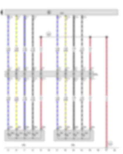
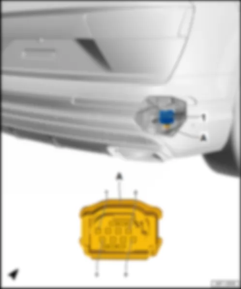
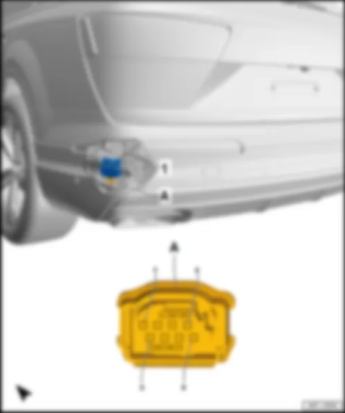
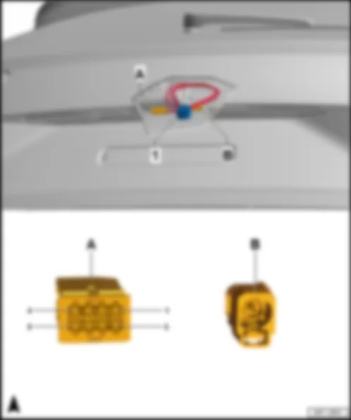
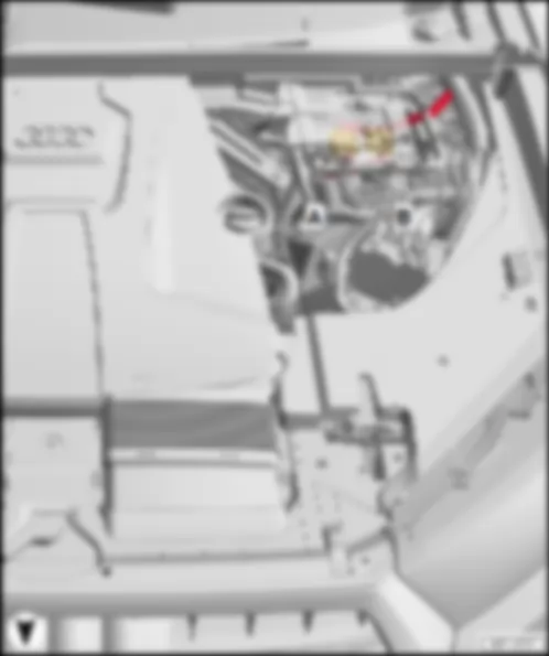
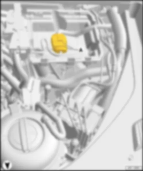
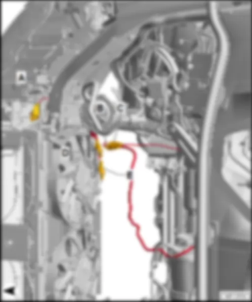
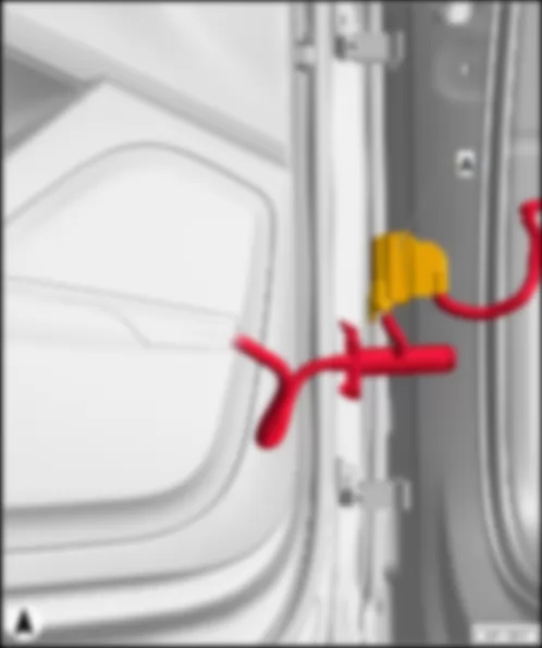
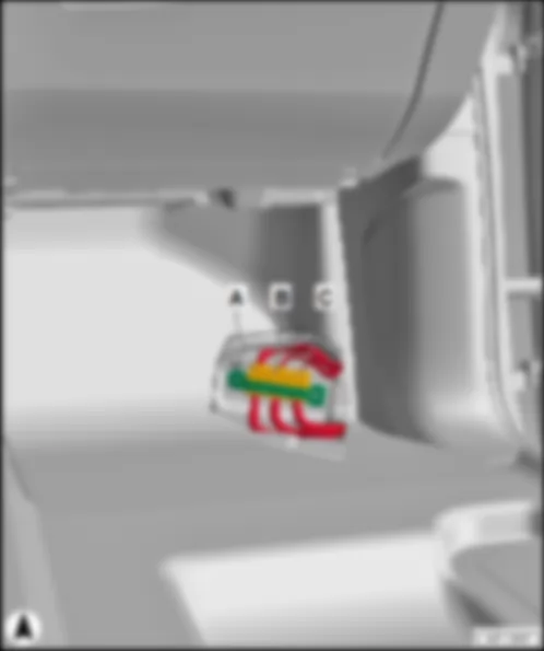
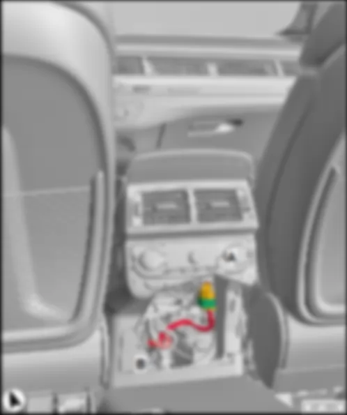
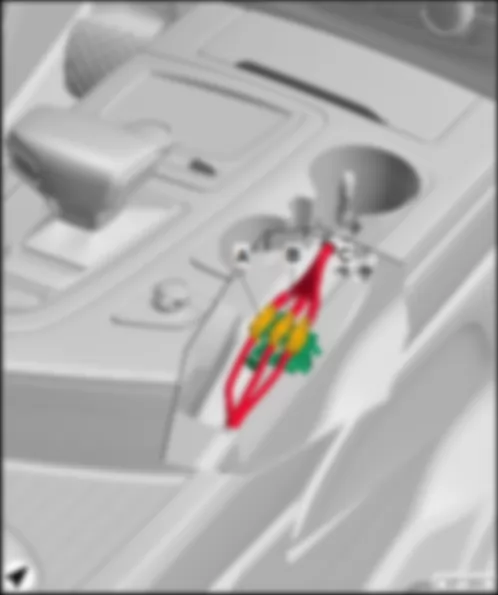
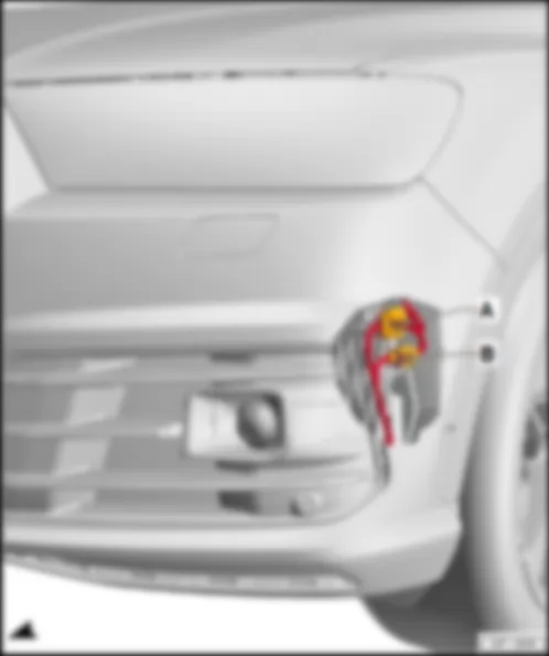
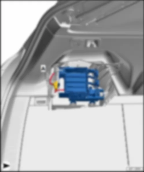
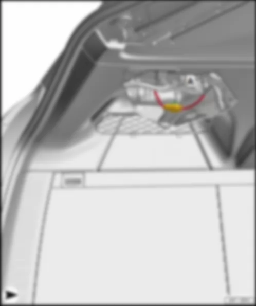
Wiring Diagram AUDI Q7 2016 - Convenience system central control unit - Left tail light - Right tail light

| J393 | Convenience system central control unit |
| M2 | Right tail light bulb |
| MX3 | Left tail light |
| M4 | Left tail light bulb |
| MX4 | Right tail light |
| M6 | Rear left turn signal bulb |
| M8 | Rear right turn signal bulb |
| M9 | Left brake light bulb |
| M10 | Right brake light bulb |
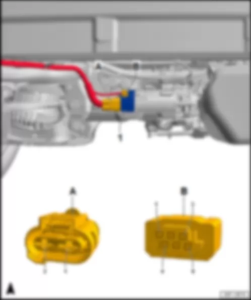
| T4aq | 4-pin connector, black |
| T4ar | 4-pin connector, black |
| T5w | 5-pin connector, black |
| T5y | 5-pin connector, black |
| T17f | 17-pin connector, black |
| T17g | 17-pin connector, brown |
| 384 | Earth connection 19, in main wiring harness |
| |
| B469 | Connection 5, in main wiring harness |
| * | Only models with sequential turn signals |
Wiring Diagram AUDI Q7 2016 - Convenience system central control unit - Left tail light 2 - Right tail light 2
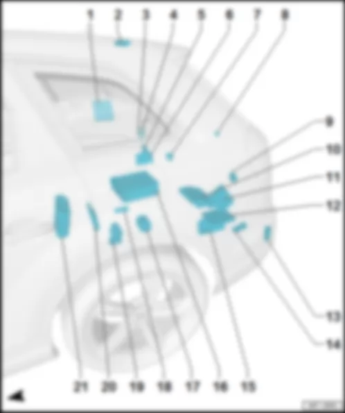
AUDI Q7 2016 Overview of control units in rear part of vehicle
Overview of control units in rear part of vehicle | | q | Connector assignment, digital sound package control unit -J525- , premium sound |
| q | Fitting location, digital sound package control unit -J525- , advanced sound |
| q | Connector assignment, digital sound package control unit -J525- , advanced sound |
| CD changer -R41- /DVD changer -R161- |
| 21 - | Digital sound package control unit -J525- |
| q | only models with high-voltage system |
| q | Fitting location, digital sound package control unit -J525- , premium sound |
| q | Connector assignment, digital sound package control unit -J525- , premium sound |
| q | Fitting location, digital sound package control unit -J525- , advanced sound |
| q | Connector assignment, digital sound package control unit -J525- , advanced sound |
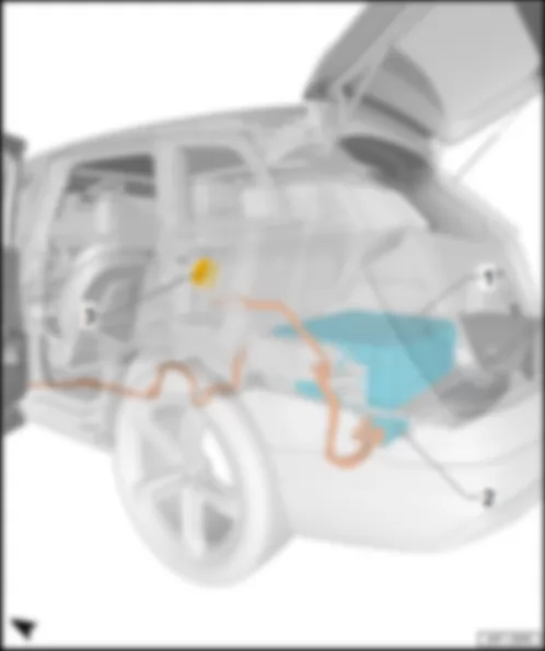
AUDI Q7 2016 Overview of additional control units in rear part of vehicle for models with high-voltage system
Overview of additional control units in rear part of vehicle for models with high-voltage system |
| Charging unit 1 for high-voltage battery -AX4- |
| q | with high-voltage battery charger control unit -J1050- |
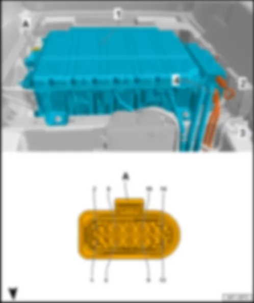
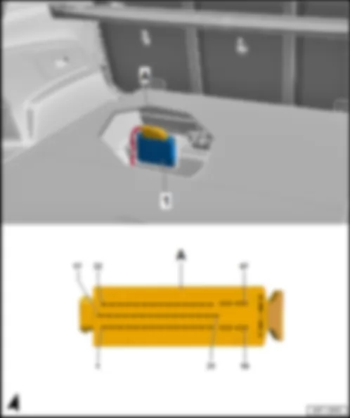
AUDI Q7 2016 Fitting location Hybrid battery unit AX1
Fitting location Hybrid battery unit -AX1- |
| At centre in luggage compartment: |
| 1 - | Hybrid battery unit -AX1- |
| q | with battery regulation control unit -J840- and high voltage battery switch box -SX6- |
| 2 - | High-voltage wire for high-voltage battery charger -P25- |
| 4 - | High-voltage wire for hybrid battery, positive terminal -P1- |
| Connector assignment, Hybrid battery unit -AX1- |
| -T14h- (A) | Designation | | -T14h- (A) | Designation |
| 1 | Hybrid CAN bus, high, to B816 connection 2 (hybrid CAN bus, high) in main wiring harness | | 8 | |
| 2 | Hybrid CAN bus, low, to B817 connection 2 (hybrid CAN bus, low) in main wiring harness | | 9 | Terminal 31, to 675 earth point 2 on right in luggage compartment |
| 3 | Airbag control unit -J234- | | 10 | Terminal 30, from fuse carrier 4 -ST4- in fuse holder F -SF- |
| 4 | Maintenance connector for high-voltage system -TW- (pilot line) | | 11 | High voltage heater (PTC) -J848- (pilot line) |
| 5 | Coolant pump relay -J235- | | 12 | Airbag control unit -J234- |
| 6 | Maintenance connector for high-voltage system -TW- | | 13 | |
| 7 | Coolant pump for high-voltage battery -V590- | | 14 | |
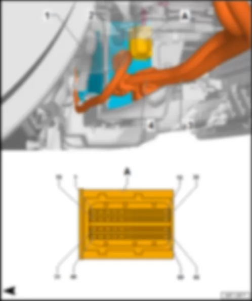
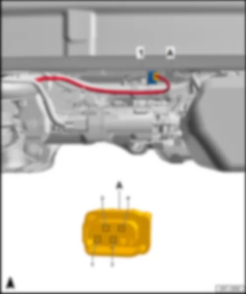
AUDI Q7 2016 Fitting location, charging unit 1 for high-voltage battery AX4
Fitting location, charging unit 1 for high-voltage battery -AX4- |
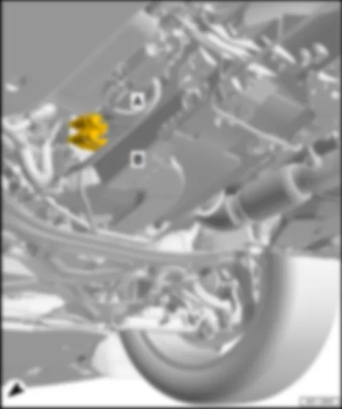
| On underbody at rear, behind rear axle. |
| 1 - | Charging unit 1 for high-voltage battery -AX4- |
| q | with high-voltage battery charger control unit -J1050- |
| 2 - | High-voltage wire for high-voltage heater (PTC) -P11- |
| 3 - | High-voltage wire for charging socket |
| A - | 60-pin connector -T60a- , black |
| Connector assignment of charging unit 1 for high-voltage battery -AX4- |
| -T60a- (A) | Designation | | -T60a- (A) | Designation | | -T60a- (A) | Designation |
| 1 | Terminal 30, from fuse carrier 4 -ST4- in fuse holder F -SF- | | 21 | Module for battery charge selector buttons -EX32- | | 41 | |
| 2 | | | 22 | Module for battery charge selector buttons -EX32- | | 42 | |
| 3 | Earth connection module for battery charge selector buttons -EX32- | | 23 | High-voltage battery charging socket 1 -UX4- | | 43 | |
| 4 | Module for battery charge selector buttons -EX32- | | 24 | High-voltage battery charging socket 1 -UX4- | | 44 | |
| 5 | Module for battery charge selector buttons -EX32- | | 25 | Module for battery charge selector buttons -EX32- | | 45 | |
| 6 | Module for battery charge selector buttons -EX32- | | 26 | Module for battery charge selector buttons -EX32- | | 46 | |
| 7 | | | 27 | Temperature sender for charging socket 1 -G853- in high-voltage battery charging socket 1 -UX4- | | 47 | |
| 8 | High-voltage battery charging socket 1 -UX4-1) 2) | | 28 | Temperature sender for charging socket 1 -G853- in high-voltage battery charging socket 1 -UX4- | | 48 | |
| 9 | Hybrid CAN bus, high, to B816 connection 2 (hybrid CAN bus, high) in main wiring harness | | 29 | | | 49 | |
| 10 | Hybrid CAN bus, low, to B817 connection 2 (hybrid CAN bus, low) in main wiring harness | | 30 | | | 50 | |
| 11 | | | 31 | Actuator for high-voltage charging flap lock 1 -F496- | | 51 | |
| 12 | | | 32 | Actuator for high-voltage charging flap lock 1 -F496- | | 52 | |
| 13 | | | 33 | | | 53 | |
| 14 | | | 34 | | | 54 | |
| 15 | | | 35 | | | 55 | |
| 16 | Actuator for high-voltage charging socket lock 1 -F498- in high-voltage battery charging socket 1 -UX4- | | 36 | | | 56 | |
| 17 | Actuator for high-voltage charging socket lock 1 -F498- in high-voltage battery charging socket 1 -UX4- | | 37 | | | 57 | |
| 18 | Actuator for high-voltage charging socket lock 1 -F498- in high-voltage battery charging socket 1 -UX4- | | 38 | | | 58 | |
| 19 | Actuator for high-voltage charging socket lock 1 -F498- in high-voltage battery charging socket 1 -UX4- | | 39 | | | 59 | |
| 20 | | | 40 | | | 60 | Terminal 31, to 676 earth point 2 on left in luggage compartment |
| 1) for models with Japan equipment only |
| 2) for models for American markets only |
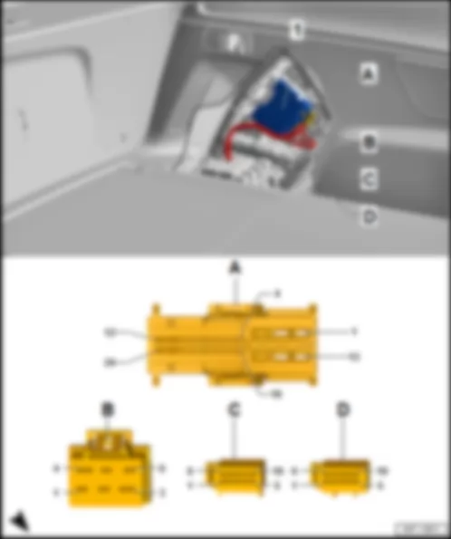
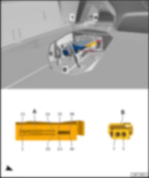
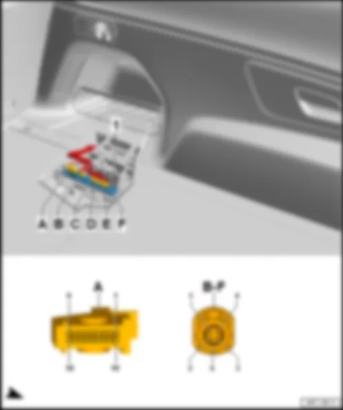
AUDI Q7 2016 Fitting location, trailer detector control unit J345
Fitting location, trailer detector control unit -J345- |
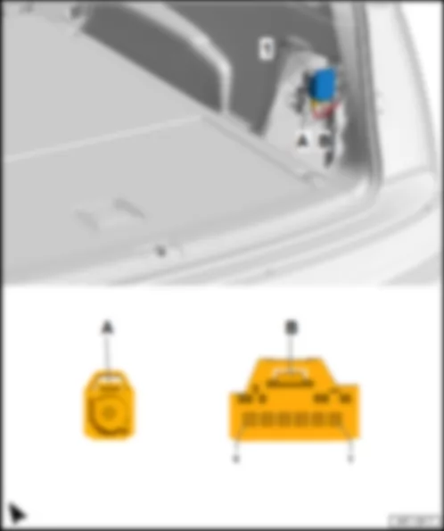
| on left in luggage compartment, behind the side trim. |
| 1 - | Trailer detector control unit -J345- |
| B - | 6-pin connector -T6d- , black |
| D - | 10-pin connector -T10c- , red |
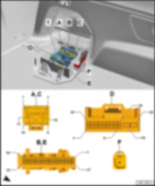
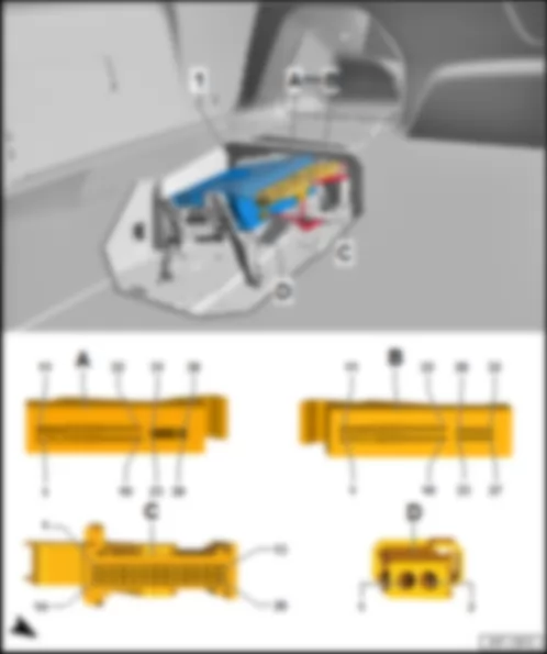
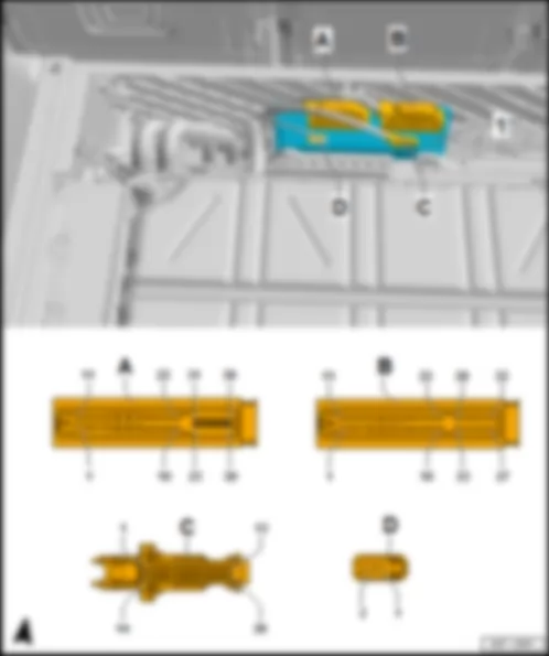
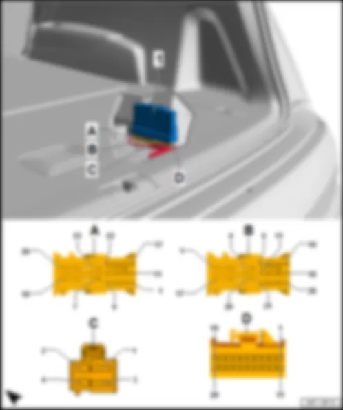
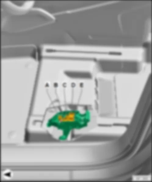
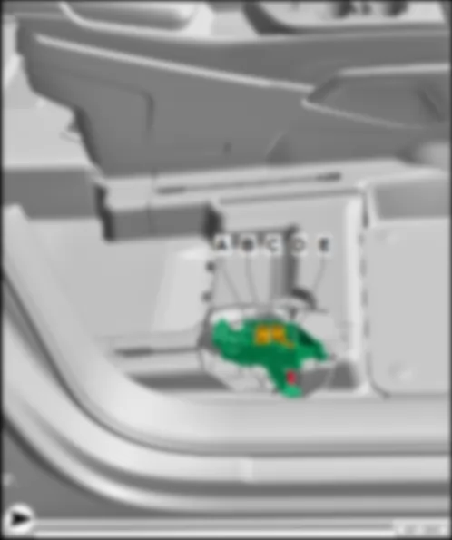
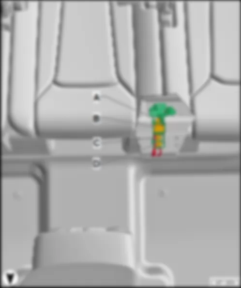
AUDI Q7 2016 Fitting location, convenience system central control unit J393
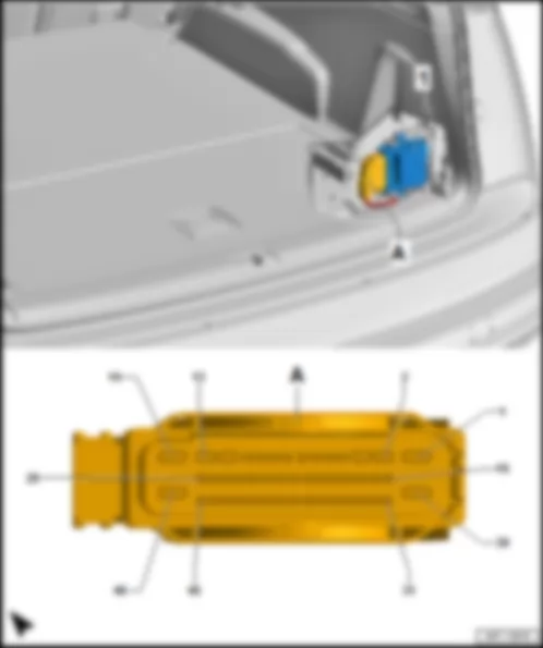
Fitting location, convenience system central control unit -J393- |
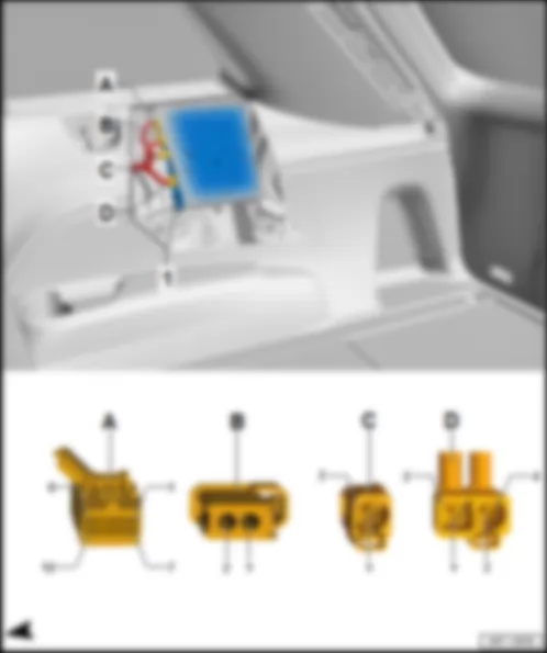
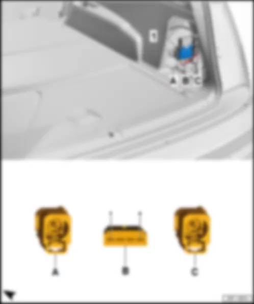
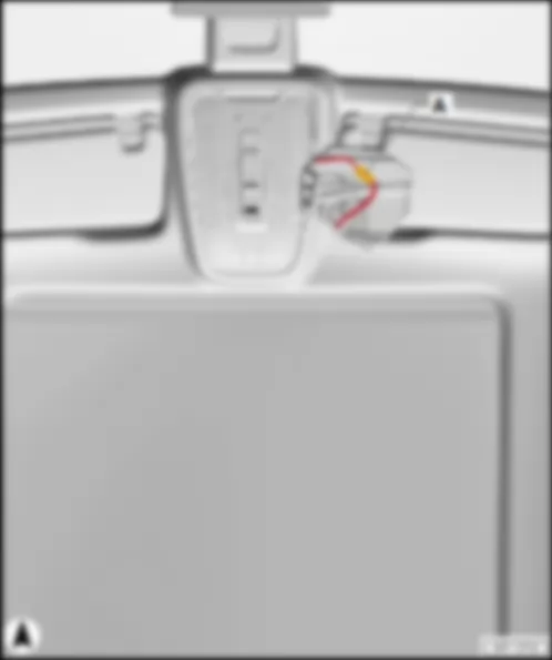
| On left in luggage compartment, behind the side trim, under the fuse and relay carrier. |
| 1 - | Convenience system central control unit -J393- |
| B - | 32-pin connector -T32g- , black |
| D - | 20-pin connector -T20b- , black |
| Connector assignment, convenience system central control unit -J393- |
| -T17g- (A) | Designation | | -T32g- (B) | Designation | | -T17f- (C) | Designation |
| 1 | Right reversing light bulb -M17- in right tail light module 2 -MX6- | | 1 | Left number plate light -X4- /right number plate light -X5- | | 1 | Right reversing light bulb 2 -M87- in right tail light module 2 -MX6- |
| 2 | Left reversing light bulb 2 -M86- in left tail light module 2 -MX5- | | 2 | | | 2 | Left brake and tail light bulb -M21- in left tail light module 2 -MX5- |
| 3 | Right brake light bulb -M10- in right tail light module -MX4- | | 3 | | | 3 | Left reversing light bulb -M16- in left tail light module 2 -MX5- |
| 4 | Left tail light bulb -M4- in left tail light module -MX3- | | 4 | | | 4 | Left brake light bulb -M9- in left tail light module -MX3- |
| 5 | Terminal 58s, to B733 connection 3 (58s) in main wiring harness | | 5 | LIN bus, to rear lid power opening control unit -J938- | | 5 | Rear right turn signal bulb -M8- in right tail light module -MX4- |
| 6 | Rear right fog light bulb -L47- in right tail light module 2 -MX6- | | 6 | | | 6 | Rear left fog light bulb -L46- in left tail light module 2 -MX5- |
| 7 | Right brake and tail light bulb -M22- in right tail light module 2 -MX6- | | 7 | | | 7 | Right tail light bulb -M2- in right tail light module -MX4- |
| 8 | | | 8 | | | 8 | Rear lid power opening control unit -J938- |
| 9 | | | 9 | | | 9 | |
| 10 | | | 10 | Engine control unit -J623- | | 10 | |
| 11 | | | 11 | | | 11 | Left tail light module -MX3- /right tail light module -MX4- |
| 12 | | | 12 | Brake light switch -F- | | 12 | |
| 13 | | | 13 | Rear left vehicle level sender -G76-1) | | 13 | |
| 14 | Rear left turn signal bulb -M6- in left tail light module -MX3- | | 14 | Front left vehicle level sender -G78-1), 2) | | 14 | |
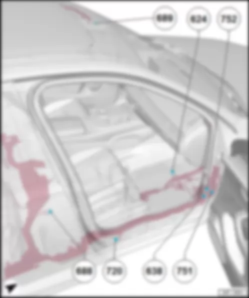
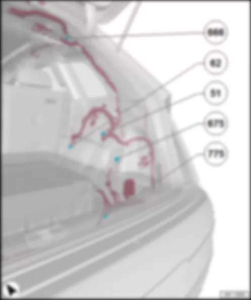
| 15 | Terminal 31, to 370 earth connection 5 in main wiring harness
676 Earth point 2 on left in luggage compartment | | 15 | Front left vehicle level sender -G78-1), 2) | | 15 | Terminal 31, to 370 earth connection 5 in main wiring harness
676 Earth point 2 on left in luggage compartment |
| 16 | Terminal 30, from fuse carrier 1 -ST1- in fuse holder F -SF- | | 16 | Suppression filter -C24- /additional brake light bulb -M25- | | 16 | Terminal 30, from fuse carrier 3 -ST3- in fuse holder F -SF- |
| 17 | Terminal 30, from fuse carrier 1 -ST1- in fuse holder F -SF- | | 17 | Terminal 15, from B281 positive connection 5 (15a) in main wiring harness
Onboard supply control unit -J519- | | 17 | |
| | | | 18 | Terminal 15 voltage supply relay -J329- | | | |
| | | | 19 | LIN bus, to B528 connection 1 (LIN bus) in main wiring harness3)
Anti-theft alarm sensor -G578-
Heated windscreen control unit -J505- | | | |
| | | | 20 | LIN bus, to alarm horn -H12- | | | |
| | | | 21 | Front left vehicle level sender -G78-1), 2) | | | |
| | | | 22 | | | | |
| | | | 23 | | | | |
| | | | 24 | | | | |
| | | | 25 | | | | |
| | | | 26 | | | | |
| | | | 27 | | | | |
| | | | 28 | | | | |
| | | | 29 | Rear left vehicle level sender -G76-1) | | | |
| | | | 30 | Tank filler flap locking motor -V155- | | | |
| | | | 31 | Tank filler flap locking motor -V155- | | | |
| | | | 32 | Heated rear window relay -J9- | | | |
| 1) Only models without running gear control unit -J775- |
| 2) Only models with LED matrix beam headlights |
| 3) Only models with anti-theft alarm sensor with interior monitoring and heated windscreen control unit -J505- |
| -T20b- (D) | Designation | | -T32h- (E) | Designation | | -T32h- (E) | Designation |
| 1 | Interior aerial 1 for entry and start system -R138- | | 1 | Convenience CAN bus, low, to B406 connection 1 (convenience CAN bus, low) in main wiring harness
Data bus diagnostic interface -J533- | | 17 | Rear lid closed sender 1 -G525- /rear lid closed sender 2 -G526- |
| 2 | Left aerial for entry and start authorisation -R200- | | 2 | Convenience CAN bus, high, from B397 connection 1 (convenience CAN bus, high) in main wiring harness
Data bus diagnostic interface -J533- | | 18 | |
| 3 | Left aerial for entry and start authorisation -R200- | | 3 | | | 19 | |
| 4 | | | 4 | | | 20 | Rear left vehicle level sender -G76-1) |
| 5 | Right aerial for entry and start authorisation -R201- | | 5 | | | 21 | Fuel gauge sender -G- |
| 6 | Right aerial for entry and start authorisation -R201- | | 6 | | | 22 | Fuel level sender 2 -G169- |
| 7 | Luggage compartment aerial for entry and start system -R137- | | 7 | | | 23 | |
| 8 | Luggage compartment aerial for entry and start system -R137- | | 8 | | | 24 | |
| 9 | | | 9 | Fuel gauge sender -G- /fuel gauge sender 2 -G169- | | 25 | Entry and start authorisation button -E408- |
| 10 | Interior aerial 1 for entry and start system -R138- | | 10 | Entry and start authorisation button -E408- | | 26 | Entry and start authorisation button -E408- |
| 11 | Rear lid central locking motor -V53- | | 11 | | | 27 | |
| 12 | Contact sensor for rear right exterior door handle -G418- | | 12 | Glass breakage sensor for rear window -G304- | | 28 | Contact switch in lock cylinder for rear lid, anti-theft alarm system and central locking system -F124- |
| 13 | Contact sensor for rear left exterior door handle -G417- | | 13 | Rear lid closed sender 2 -G526- | | 29 | Rear lid closed sender 1 -G525- |
| 14 | Contact sensor for front right exterior door handle -G606- | | 14 | | | 30 | Rear lid handle release button -E234- |
| 15 | Contact sensor for front left exterior door handle -G605- | | 15 | Rear lid contact switch for anti-theft alarm -F123- | | 31 | |
| 16 | | | 16 | | | 32 | |
| 17 | | | | | | | |
| 18 | | | | | | | |
| 19 | | | | | | | |
| 20 | | | | | | | |
| 1) Only models without running gear control unit -J775- |
AUDI Q7 2016 Fitting location, all-wheel drive control unit J492
Fitting location, all-wheel drive control unit -J492- |
| At front left in luggage compartment, under the trim in floor panel |
Note:
| Illustration shows fitting location for models without 3rd seat row. On models with 3rd seat row, the fitting location deviates slightly from the illustration. |
| 1 - | All-wheel drive control unit -J492- |
| Connector assignment, all-wheel drive control unit -J492- |
| -T47a- (A) | Designation | | -T47a- (A) | Designation | | -T47a- (A) | Designation |
| 1 | Axle differential lock control unit -J647- | | 17 | Axle differential lock control unit -J647- | | 33 | |
| 2 | | | 18 | Axle differential lock control unit -J647- | | 34 | |
| 3 | | | 19 | | | 35 | Axle differential lock control unit -J647- |
| 4 | Axle differential lock control unit -J647- | | 20 | Axle differential lock control unit -J647- | | 36 | |
| 5 | | | 21 | Axle differential lock control unit -J647- | | 37 | |
| 6 | | | 22 | | | 38 | |
| 7 | | | 23 | | | 39 | |
| 8 | | | 24 | | | 40 | FlexRay bus, from data bus diagnostic interface -J533- |
| 9 | | | 25 | | | 41 | FlexRay bus, from data bus diagnostic interface -J533- |
| 10 | | | 26 | | | 42 | FlexRay bus, to data bus diagnostic interface -J533-1)
Rear wheel steering control unit -J1019-2) |
| 11 | | | 27 | | | 43 | FlexRay bus, to data bus diagnostic interface -J533-1)
Rear wheel steering control unit -J1019-2) |
| 12 | | | 28 | Terminal 15, from B281 positive connection 5 (15a) in main wiring harness
Onboard supply control unit -J519- | | 44 | Axle differential lock control unit -J647- |
| 13 | Axle differential lock control unit -J647- | | 29 | | | 45 | Axle differential lock control unit -J647- |
| 14 | Axle differential lock control unit -J647- | | 30 | | | 46 | Terminal 30, from fuse carrier 2 -ST2- in fuse holder F -SF- |
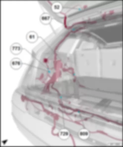
| 15 | Axle differential lock control unit -J647- | | 31 | | | 47 | Terminal 31, to 61 earth point on left C-pillar |
| 16 | Axle differential lock control unit -J647- | | 32 | Axle differential lock control unit -J647- | | | |
| 1) Only models without rear-axle steering control unit -J1019- |
| 2) Only models with rear-axle steering control unit -J1019- |
AUDI Q7 2016 Fitting location, Tyre Pressure Monitoring System control unit J502
Fitting location, Tyre Pressure Monitoring System control unit -J502- |
| On rear axle assembly carrier. |
| 1 - | Tyre Pressure Monitoring System control unit -J502- |
| Connector assignment, Tyre Pressure Monitoring System control unit -J502- |
| | | -T4k- (A) | Designation |
| 1 | Extended low CAN bus, from coupling point on left in luggage compartment -THRL-
B671 Connection 3 (CAN bus extended, low), in main wiring harness
Data bus diagnostic interface -J533- |
| 2 | Terminal 30, from coupling point on left in luggage compartment -THRL-
Fuse carrier 3 -ST3- in fuse holder F -SF- |
| 3 | Extended high CAN bus, from coupling point on left in luggage compartment -THRL-
B670 Connection 3 (CAN bus extended, high), in main wiring harness
Data bus diagnostic interface -J533- |
| 4 | Terminal 31, to coupling point on left in luggage compartment -THRL-
387 Earth connection 22 in main wiring harness
385 Earth connection 20 in main wiring harness
676 Earth point 2 on left in luggage compartment |
AUDI Q7 2016 Fitting location, digital sound package control unit J525Fitting location, digital sound package control unit -J525- |
| | |
| Fitting location, digital sound package control unit -J525- , premium sound, models without high-voltage system |
| at rear left in luggage compartment, under the trim in floor panel. |
| 1 - | Digital sound package control unit -J525- |
| B - | 2-pin connector -T2jt- , black |
| Connector assignment, digital sound package control unit -J525- |
| -T38a- (A) | Designation | | -T38a- (A) | Designation | | -T38a- (A) | Designation |
| 1 | Terminal 30, from fuse carrier 2 -ST2- in fuse holder F -SF- | | 14 | Front right bass loudspeaker -R23- | | 27 | Front right treble loudspeaker -R22- /front right mid-range and bass loudspeaker -R104- |
| 2 | Terminal 31, to 61 earth point on left C-pillar | | 15 | | | 28 | |
| 3 | | | 16 | Subwoofer -R211- | | 29 | Internal microphone -R74- |
| 4 | Subwoofer -R211- | | 17 | Front left treble loudspeaker 2 -R220- | | 30 | Internal microphone -R74- |
| 5 | Front left treble loudspeaker 2 -R220- | | 18 | Front right treble loudspeaker 2 -R221- | | 31 | Centre loudspeaker -R208- /central loudspeaker 2 -R219- |
| 6 | Front right treble loudspeaker 2 -R221- | | 19 | Rear left treble loudspeaker -R14- /rear left bass loudspeaker -R15- | | 32 | Centre loudspeaker -R208- /central loudspeaker 2 -R219- |
| 7 | Rear left treble loudspeaker -R14- /rear left bass loudspeaker -R15- | | 20 | Rear right treble loudspeaker -R16- /rear right bass loudspeaker -R17- | | 33 | Front right loudspeaker -R3- |
| 8 | Rear right treble loudspeaker -R16- /rear right bass loudspeaker -R17- | | 21 | Right effect loudspeaker -R210- | | 34 | Front right loudspeaker -R3- |
| 9 | Right effect loudspeaker -R210- | | 22 | Left effect loudspeaker -R209- | | 35 | Front left loudspeaker -R2- |
| 10 | Left effect loudspeaker -R209- | | 23 | | | 36 | Front left loudspeaker -R2- |
| 11 | Front left bass loudspeaker -R21- | | 24 | | | 37 | Front left treble loudspeaker -R20-Front left mid-range loudspeaker -R103- |
| 12 | Front left bass loudspeaker -R21- | | 25 | Ring circuit break diagnostic | | 38 | Front left treble loudspeaker -R20-Front left mid-range loudspeaker -R103- |
| 13 | Front right bass loudspeaker -R23- | | 26 | Front right treble loudspeaker -R22- /front right mid-range and bass loudspeaker -R104- | | | |
| Fitting location, digital sound package control unit -J525- , premium sound, models with high-voltage system |
| In front left of luggage compartment, in front of hybrid battery unit -AX1- . |
| 1 - | Digital sound package control unit -J525- |
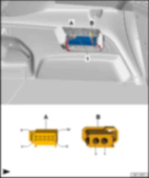
| A - | 2-pin connector -T2jt- , black |
| B - | 38-pin connector -T38a- , black |
| Connector assignment, digital sound package control unit -J525- |
| -T38a- (B) | Designation | | -T38a- (B) | Designation | | -T38a- (B) | Designation |
| 1 | Terminal 30, from fuse carrier 2 -ST2- in fuse holder F -SF- | | 14 | Front right bass loudspeaker -R23- | | 27 | Front right treble loudspeaker -R22- /front right mid-range and bass loudspeaker -R104- |
| 2 | Terminal 31, to 61 earth point on left C-pillar | | 15 | | | 28 | |
| 3 | | | 16 | Subwoofer -R211- | | 29 | Internal microphone -R74- |
| 4 | Subwoofer -R211- | | 17 | Front left treble loudspeaker 2 -R220- | | 30 | Internal microphone -R74- |
| 5 | Front left treble loudspeaker 2 -R220- | | 18 | Front right treble loudspeaker 2 -R221- | | 31 | Centre loudspeaker -R208- /central loudspeaker 2 -R219- |
| 6 | Front right treble loudspeaker 2 -R221- | | 19 | Rear left treble loudspeaker -R14- /rear left bass loudspeaker -R15- | | 32 | Centre loudspeaker -R208- /central loudspeaker 2 -R219- |
| 7 | Rear left treble loudspeaker -R14- /rear left bass loudspeaker -R15- | | 20 | Rear right treble loudspeaker -R16- /rear right bass loudspeaker -R17- | | 33 | Front right loudspeaker -R3- |
| 8 | Rear right treble loudspeaker -R16- /rear right bass loudspeaker -R17- | | 21 | Right effect loudspeaker -R210- | | 34 | Front right loudspeaker -R3- |
| 9 | Right effect loudspeaker -R210- | | 22 | Left effect loudspeaker -R209- | | 35 | Front left loudspeaker -R2- |
| 10 | Left effect loudspeaker -R209- | | 23 | | | 36 | Front left loudspeaker -R2- |
| 11 | Front left bass loudspeaker -R21- | | 24 | | | 37 | Front left treble loudspeaker -R20-Front left mid-range loudspeaker -R103- |
| 12 | Front left bass loudspeaker -R21- | | 25 | Ring circuit break diagnostic | | 38 | Front left treble loudspeaker -R20-Front left mid-range loudspeaker -R103- |
| 13 | Front right bass loudspeaker -R23- | | 26 | Front right treble loudspeaker -R22- /front right mid-range and bass loudspeaker -R104- | | | |
| Fitting location, digital sound package control unit -J525- , advanced sound, models without high-voltage system |
| at rear left in luggage compartment, under the trim in floor panel. |
| 1 - | Digital sound package control unit -J525- |
| A - | 38-pin connector -T38a- , black |
| C - | 26-pin connector -T26a- , blue |
| D - | 2-pin connector -T2jt- , black |
| Connector assignment, digital sound package control unit -J525- |
| -T38a- (A) | Designation | | -T32e- (B) | Designation | | -T26a- (C) | Designation |
| 1 | Terminal 30, from fuse carrier 1 (30) -S204- in fuse holder F -SF- | | 1 | | | 1 | Front left treble loudspeaker 2 -R220- |
| 2 | Terminal 31, to 676 earth point 2 on left in luggage compartment | | 2 | | | 2 | Front right treble loudspeaker 2 -R221- |
| 3 | Subwoofer -R211- | | 3 | | | 3 | Front left mid-range loudspeaker 2 -R276- |
| 4 | Front left bass loudspeaker -R21- | | 4 | | | 4 | Front right mid-range loudspeaker 2 -R277- |
| 5 | Front right bass loudspeaker -R23- | | 5 | Front left mid-range loudspeaker -R103- | | 5 | Rear left treble loudspeaker 2 -R217- |
| 6 | Rear left bass loudspeaker -R15- | | 6 | Front right mid-range loudspeaker -R104- | | 6 | Rear right treble loudspeaker 2 -R218- |
| 7 | Rear right bass loudspeaker -R17- | | 7 | Rear left mid-range loudspeaker -R105- | | 7 | Rear left treble loudspeaker -R14- |
| 8 | Control motor for front left treble speaker -V344- | | 8 | Rear right mid-range loudspeaker -R106- | | 8 | Rear right treble loudspeaker -R16- |
| 9 | Control motor for front left treble speaker -V344- | | 9 | Left effect loudspeaker -R209- | | 9 | |
| 10 | Control motor for front left treble speaker -V344- | | 10 | Centre loudspeaker -R208- | | 10 | |
| 11 | | | 11 | | | 11 | |
| 12 | | | 12 | | | 12 | |
| 13 | | | 13 | Ring circuit break diagnostic | | 13 | |
| 14 | | | 14 | | | 14 | Front left treble loudspeaker 2 -R220- |
| 15 | Subwoofer -R211- | | 15 | | | 15 | Front right treble loudspeaker 2 -R221- |
| 16 | Front left bass loudspeaker -R21- | | 16 | | | 16 | Front left mid-range loudspeaker 2 -R276- |
| 17 | Front right bass loudspeaker -R23- | | 17 | Front left mid-range loudspeaker -R103- | | 17 | Front right mid-range loudspeaker 2 -R277- |
| 18 | Rear left bass loudspeaker -R15- | | 18 | Front right mid-range loudspeaker -R104- | | 18 | Rear left treble loudspeaker 2 -R217- |
| 19 | Rear right bass loudspeaker -R17- | | 19 | Rear left mid-range loudspeaker -R105- | | 19 | Rear right treble loudspeaker 2 -R218- |
| 20 | Control motor for front right treble speaker -V345- | | 20 | Rear right mid-range loudspeaker -R106- | | 20 | Rear left treble loudspeaker -R14- |
| 21 | Control motor for front right treble speaker -V345- | | 21 | Left effect loudspeaker -R209- | | 21 | Rear right treble loudspeaker -R16- |
| 22 | Control motor for front right treble speaker -V345- | | 22 | Centre loudspeaker -R208- | | 22 | |
| 23 | Internal microphone -R74- | | 23 | Right effect loudspeaker -R210- | | 23 | |
| 24 | | | 24 | | | 24 | |
| 25 | | | 25 | Centre loudspeaker 2 -R219- | | 25 | |
| 26 | | | 26 | Front left treble loudspeaker -R20- | | 26 | |
| 27 | | | 27 | Front right treble loudspeaker -R22- | | | |
| 28 | | | 28 | Right effect loudspeaker -R210- | | | |
| 29 | | | 29 | | | | |
| 30 | | | 30 | Centre loudspeaker 2 -R219- | | | |
| 31 | Internal microphone -R74- | | 31 | Front left treble loudspeaker -R20- | | | |
| 32 | | | 32 | Front right treble loudspeaker -R22- | | | |
| 33 | | | | | | | |
| 34 | | | | | | | |
| 35 | | | | | | | |
| 36 | | | | | | | |
| 37 | | | | | | | |
| 38 | | | | | | | |
| Fitting location, digital sound package control unit -J525- , advanced sound, models with high-voltage system |
| In front left of luggage compartment, in front of hybrid battery unit -AX1- . |
| 1 - | Digital sound package control unit -J525- |
| A - | 38-pin connector -T38a- , black |
| B - | 32-pin connector -T32e- , black |
| C - | 26-pin connector -T26a- , blue |
| D - | 2-pin connector -T2jt- , black |
| Connector assignment, digital sound package control unit -J525- |
| -T38a- (A) | Designation | | -T32e- (B) | Designation | | -T26a- (C) | Designation |
| 1 | Terminal 30, from fuse carrier 1 (30) -S204- in fuse holder F -SF- | | 1 | | | 1 | Front left treble loudspeaker 2 -R220- |
| 2 | Terminal 31, to 676 earth point 2 on left in luggage compartment | | 2 | | | 2 | Front right treble loudspeaker 2 -R221- |
| 3 | Subwoofer -R211- | | 3 | | | 3 | Front left mid-range loudspeaker 2 -R276- |
| 4 | Front left bass loudspeaker -R21- | | 4 | | | 4 | Front right mid-range loudspeaker 2 -R277- |
| 5 | Front right bass loudspeaker -R23- | | 5 | Front left mid-range loudspeaker -R103- | | 5 | Rear left treble loudspeaker 2 -R217- |
| 6 | Rear left bass loudspeaker -R15- | | 6 | Front right mid-range loudspeaker -R104- | | 6 | Rear right treble loudspeaker 2 -R218- |
| 7 | Rear right bass loudspeaker -R17- | | 7 | Rear left mid-range loudspeaker -R105- | | 7 | Rear left treble loudspeaker -R14- |
| 8 | Control motor for front left treble speaker -V344- | | 8 | Rear right mid-range loudspeaker -R106- | | 8 | Rear right treble loudspeaker -R16- |
| 9 | Control motor for front left treble speaker -V344- | | 9 | Left effect loudspeaker -R209- | | 9 | |
| 10 | Control motor for front left treble speaker -V344- | | 10 | Centre loudspeaker -R208- | | 10 | |
| 11 | | | 11 | | | 11 | |
| 12 | | | 12 | | | 12 | |
| 13 | | | 13 | Ring circuit break diagnostic | | 13 | |
| 14 | | | 14 | | | 14 | Front left treble loudspeaker 2 -R220- |
| 15 | Subwoofer -R211- | | 15 | | | 15 | Front right treble loudspeaker 2 -R221- |
| 16 | Front left bass loudspeaker -R21- | | 16 | | | 16 | Front left mid-range loudspeaker 2 -R276- |
| 17 | Front right bass loudspeaker -R23- | | 17 | Front left mid-range loudspeaker -R103- | | 17 | Front right mid-range loudspeaker 2 -R277- |
| 18 | Rear left bass loudspeaker -R15- | | 18 | Front right mid-range loudspeaker -R104- | | 18 | Rear left treble loudspeaker 2 -R217- |
| 19 | Rear right bass loudspeaker -R17- | | 19 | Rear left mid-range loudspeaker -R105- | | 19 | Rear right treble loudspeaker 2 -R218- |
| 20 | Control motor for front right treble speaker -V345- | | 20 | Rear right mid-range loudspeaker -R106- | | 20 | Rear left treble loudspeaker -R14- |
| 21 | Control motor for front right treble speaker -V345- | | 21 | Left effect loudspeaker -R209- | | 21 | Rear right treble loudspeaker -R16- |
| 22 | Control motor for front right treble speaker -V345- | | 22 | Centre loudspeaker -R208- | | 22 | |
| 23 | Internal microphone -R74- | | 23 | Right effect loudspeaker -R210- | | 23 | |
| 24 | | | 24 | | | 24 | |
| 25 | | | 25 | Centre loudspeaker 2 -R219- | | 25 | |
| 26 | | | 26 | Front left treble loudspeaker -R20- | | 26 | |
| 27 | | | 27 | Front right treble loudspeaker -R22- | | | |
| 28 | | | 28 | Right effect loudspeaker -R210- | | | |
| 29 | | | 29 | | | | |
| 30 | | | 30 | Centre loudspeaker 2 -R219- | | | |
| 31 | Internal microphone -R74- | | 31 | Front left treble loudspeaker -R20- | | | |
| 32 | | | 32 | Front right treble loudspeaker -R22- | | | |
| 33 | | | | | | | |
| 34 | | | | | | | |
| 35 | | | | | | | |
| 36 | | | | | | | |
| 37 | | | | | | | |
| 38 | | | | | | | |
| Fitting location, garage door operation control unit -J530- |
| on centre left behind rear bumper cover. |
| 1 - | Garage door operation control unit -J530- |
| Connector assignment, garage door operation control unit -J530- |
| | | -T5d- (A) | Designation |
| 1 | Terminal 30, from fuse carrier 3 -ST3- in fuse holder F -SF- |
| 2 | Terminal 31, to 676 earth point 2 on left in luggage compartment |
| 3 | LIN bus, from B549 connection 2 (LIN bus) in main wiring harness
Onboard supply control unit -J519- |
| 4 | wiring open end -R999- , near rear seat bench |
| 5 | wiring open end -R999- , near rear seat bench |
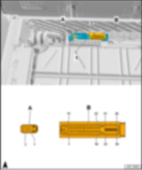
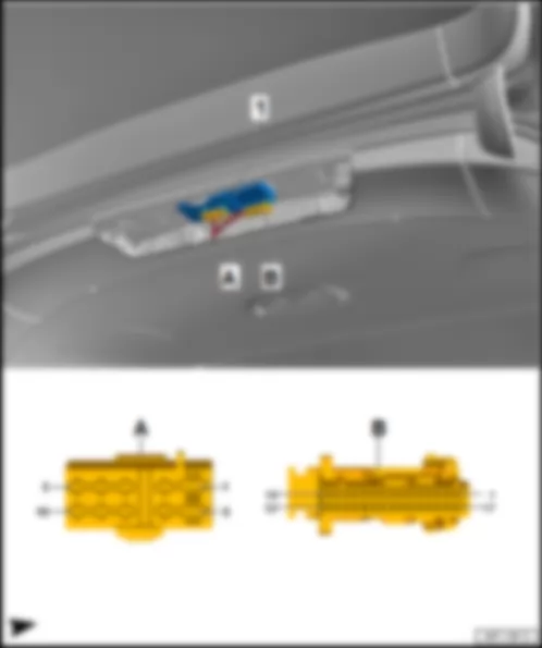
AUDI Q7 2016 Fitting location, rear lid control unit J605
Fitting location, rear lid control unit -J605- |
| At rear centre on roof cross member under roof edge trim. |
| 1 - | Rear lid control unit -J605- |
| B - | 32-pin connector -T32b- , black |
| Connector assignment for rear lid control unit -J605- |
| -T10q- (A) | Designation | | -T32b- (B) | Designation | | -T32b- (B) | Designation |
| 1 | Terminal 30, from fuse carrier 1 -ST1- in fuse holder F -SF- | | 1 | | | 17 | |
| 2 | Motor 1 for rear lid -V444- | | 2 | | | 18 | |
| 3 | Motor 2 for rear lid -V445- | | 3 | | | 19 | |
| 4 | Motor 1 for rear lid -V444- | | 4 | | | 20 | |
| 5 | Power latching motor for rear lid -V382- | | 5 | Rear lid warning buzzer -H32- | | 21 | Rear lid warning buzzer -H32- |
| 6 | Terminal 31, to 676 earth point 2 on left in luggage compartment | | 6 | Motor 1 for luggage compartment cover -V473- | | 22 | |
| 7 | Motor 1 for luggage compartment cover -V473- | | 7 | Power latching motor for rear lid -V382- | | 23 | Motor 1 for luggage compartment cover -V473- |
| 8 | Motor 1 for luggage compartment cover -V473- | | 8 | | | 24 | |
| 9 | Motor 2 for rear lid -V445- | | 9 | | | 25 | |
| 10 | Power latching motor for rear lid -V382- | | 10 | Motor 1 for rear lid -V444- | | 26 | Motor 1 for rear lid -V444- |
| | | | 11 | | | 27 | Motor 1 for rear lid -V444- |
| | | | 12 | | | 28 | Motor 1 for rear lid -V444- |
| | | | 13 | Locking button in rear lid -E806-1) | | 29 | Motor 1 for luggage compartment cover -V473- |
| | | | 14 | Locking button in rear lid -E806-1)
Button to close rear lid in luggage compartment -E406-2) | | 30 | |
| | | | 15 | | | 31 | Convenience CAN bus, low, to B406 connection 1 (convenience CAN bus, low) in main wiring harness
Data bus diagnostic interface -J533- |
| | | | 16 | | | 32 | Convenience CAN bus, high, from B397 connection 1 (convenience CAN bus, high) in main wiring harness
Data bus diagnostic interface -J533- |
| 1) Only models with entry and start authorisation |
| 2) Only models without entry and start authorisation |
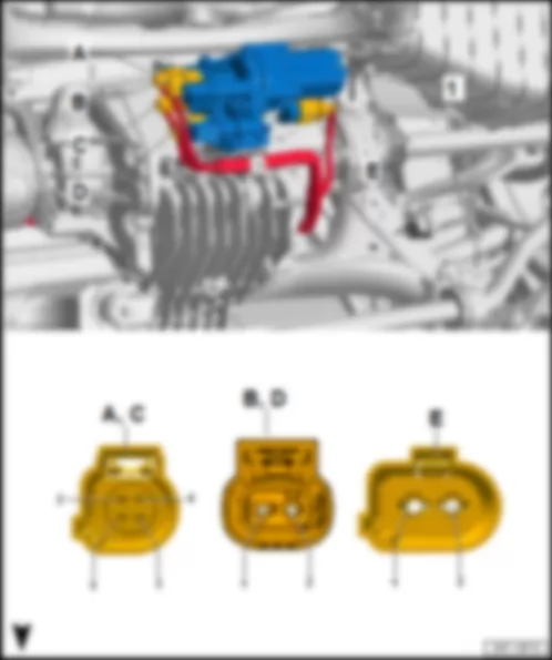
AUDI Q7 2016 Fitting location Axle differential lock control unit J647
Fitting location Axle differential lock control unit -J647- |
| 1 - | Axle differential lock control unit -J647- |
| B - | 2-pin connector -T2er- , black |
| q | from all-wheel drive control unit -J492- |
| D - | 2-pin connector -T2es- , brown |
| q | from all-wheel drive control unit -J492- |
| E - | 2-pin connector -T2et- , black |
| q | from all-wheel drive control unit -J492- |
AUDI Q7 2016 Fitting location, lane change assist control unit J769
Fitting location, lane change assist control unit -J769- |
| on right behind rear bumper cover. |
| 1 - | Lane change assist control unit -J769- |
| Connector assignment, lane change assist control unit -J769- |
| -T8g- (A) | Designation | | -T8g- (A) | Designation |
| 1 | Terminal 31, to 470 earth connection 1 in rear bumper wiring harness
Coupling point at right on rear bumper -TSFHR-
385 Earth connection 20 in main wiring harness
676 Earth point 2 on left in luggage compartment | | 5 | Lane change assist control unit 2 -J770- |
| 2 | Extended CAN bus, high, to E143 connection 1 (extended CAN bus, high) in main wiring harness
Coupling point at right on rear bumper -TSFHR-
B670 Connection 3 (CAN bus extended, high), in main wiring harness
Data bus diagnostic interface -J533- | | 6 | Lane change assist control unit 2 -J770- |
| 3 | Extended CAN bus, low, to E144 connection 1 (extended CAN bus, low) in bumper wiring harness
Coupling point at right on rear bumper -TSFHR-
B671 Connection 3 (CAN bus extended, low), in main wiring harness
Data bus diagnostic interface -J533- | | 7 | |
| 4 | | | 8 | Terminal 30, from X270 connection (30) in rear bumper wiring harness
Coupling point at right on rear bumper -TSFHR-
Fuse carrier 3 -ST3- in fuse holder F -SF- |
AUDI Q7 2016 Fitting location, lane change assist control unit 2 J770
Fitting location, lane change assist control unit 2 -J770- |
| on left behind rear bumper cover. |
| 1 - | Lane change assist control unit 2 -J770- |
| Connector assignment, lane change assist control unit 2 -J770- |
| -T8f- (A) | Designation | | -T8f- (A) | Designation |
| 1 | Terminal 31, to 470 earth connection 1 in rear bumper wiring harness
Coupling point at right on rear bumper -TSFHR-
385 Earth connection 20 in main wiring harness
676 Earth point 2 on left in luggage compartment | | 5 | Lane change assist control unit -J769- |
| 2 | Extended CAN bus, high, to E143 connection 1 (extended CAN bus, high) in main wiring harness
Coupling point at right on rear bumper -TSFHR-
B670 Connection 3 (CAN bus extended, high), in main wiring harness
Data bus diagnostic interface -J533- | | 6 | Lane change assist control unit -J769- |
| 3 | Extended CAN bus, low, to E144 connection 1 (extended CAN bus, low) in bumper wiring harness
Coupling point at right on rear bumper -TSFHR-
B671 Connection 3 (CAN bus extended, low), in main wiring harness
Data bus diagnostic interface -J533- | | 7 | |
| 4 | | | 8 | Terminal 30, from X270 connection (30) in rear bumper wiring harness
Coupling point at right on rear bumper -TSFHR-
Fuse carrier 3 -ST3- in fuse holder F -SF- |
AUDI Q7 2016 Fitting location Reversing camera system control unit J772
Fitting location Reversing camera system control unit -J772- |
| in rear lid button handle. |
| 1 - | Reversing camera system control unit -J772- |
| B - | 2-pin connector -T2dw- , blue-grey |
| q | to control unit for information electronics 1 -J794- |
| Connector assignment, reversing camera system control unit -J772- |
| -T8o- (A) | Designation | | -T8o- (A) | Designation |
| 1 | Terminal 30, from fuse carrier 3 -ST3- in fuse holder F -SF- | | 5 | Terminal 31 to 391 earth connection 26 in main wiring harness
392 Earth connection 27 in main wiring harness
384 Earth connection 19 in main wiring harness
667 Earth point on rear left of roof |
| 2 | | | 6 | |
| 3 | | | 7 | |
| 4 | Extended high CAN bus, from B668 connection 2 (extended high CAN bus) in main wiring harness
B670 Connection 3 (CAN bus extended, high), in main wiring harness
Data bus diagnostic interface -J533- | | 8 | Extended CAN bus, low, from B669 connection 2 (extended CAN bus, low) in main wiring harness
B671 Connection 3 (CAN bus extended, low), in main wiring harness
Data bus diagnostic interface -J533- |
AUDI Q7 2016 Fitting location control unit for seat adjustment, row 3 J857
Fitting location control unit for seat adjustment, row 3 -J857- |
| on right in luggage compartment, behind side trim, on wheel housing. |
| 1 - | Control unit for seat adjustment, row 3 -J857- |
| B - | 26-pin connector -T26e- , blue |
| D - | 20-pin connector -T20m- , brown |
| Connector assignment control unit for seat adjustment, row 3 -J857- |
| -T26d- (A) | Designation | | -T26d- (A) | Designation | | -T26d- (A) | Designation |
| 1 | Backrest adjustment sender for left seat in row 3 -G633- | | 10 | | | 19 | |
| 2 | Left backrest adjustment warning lamp 1 for seat row 3 -K289- | | 11 | | | 20 | |
| 3 | Left backrest adjustment warning lamp 2 for seat row 3 -K290- | | 12 | Backrest adjustment limit switch 2 for left seat in row 3 (unlocked) -F533- | | 21 | |
| 4 | Backrest adjustment limit switch for left seat in row 3 (locked) -F530- | | 13 | Backrest adjustment limit switch for right seat in row 3 (locked) -F526- | | 22 | |
| 5 | Earth, to B570 connection 37 in main wiring harness | | 14 | Backrest adjustment limit switch for right seat in row 3 (unlocked) -F527- | | 23 | |
| 6 | | | 15 | Backrest adjustment limit switch 2 for right seat in row 3 (locked) -F528- | | 24 | |
| 7 | | | 16 | | | 25 | |
| 8 | | | 17 | Backrest adjustment limit switch 2 for left seat in row 3 (locked) -F532- | | 26 | |
| 9 | | | 18 | Backrest adjustment limit switch for left seat in row 3 (unlocked) -F531- | | | |
| -T26e- (B) | Designation | | -T26e- (B) | Designation | | -T26e- (B) | Designation |
| 1 | | | 10 | | | 19 | |
| 2 | | | 11 | | | 20 | Locking pawl motor 2 for right backrest adjustment, row 3 -F544- |
| 3 | Backrest adjustment motor for right seat, row 3 -V361- | | 12 | | | 21 | |
| 4 | Locking pawl motor for left backrest adjustment, row 3 -F524- | | 13 | Right backrest adjustment warning lamp 1 for seat row 3 -K292- | | 22 | Earth, to B571 connection 38 in main wiring harness/830 earth connection 4 in rear seat adjustment wiring harness |
| 5 | | | 14 | Right backrest adjustment warning lamp 3 for seat row 3 -K294- | | 23 | |
| 6 | | | 15 | | | 24 | |
| 7 | Right backrest adjustment warning lamp 2 for seat row 3 -K293- | | 16 | Locking pawl motor for right backrest adjustment, row 3 -F525- | | 25 | |
| 8 | Backrest adjustment sender for right seat in row 3 -G634- | | 17 | | | 26 | Locking pawl motor 2 for left backrest adjustment, row 3 -F543- |
| 9 | | | 18 | Backrest adjustment motor for right seat, row 3 -V361- | | | |
| -T4fs- (C) | Designation | | -T20m- (D) | Designation | | -T20m- (D) | Designation |
| 1 | Terminal 30, from fuse carrier 2 -ST2- in fuse holder F -SF- | | 1 | Convenience CAN bus, high, from B397 connection 1 (convenience CAN bus, high) in main wiring harness
Data bus diagnostic interface -J533- | | 11 | Convenience CAN bus, low, to B406 connection 1 (convenience CAN bus, low) in main wiring harness
Data bus diagnostic interface -J533- |
| 2 | Backrest adjustment motor for left seat, row 3 -V368- | | 2 | | | 12 | |
| 3 | Terminal 31, to 370 earth connection 5 in main wiring harness
676 Earth point 2 on left in luggage compartment | | 3 | | | 13 | |
| 4 | Backrest adjustment motor for left seat, row 3 -V368- | | 4 | | | 14 | Right backrest adjustment button for seat, row 3 -E549- |
| | | | 5 | Left backrest adjustment button 2 for seat row 3 -E801- | | 15 | Left backrest adjustment button for seat, row 3 -E565- |
| | | | 6 | Backrest adjustment limit switch 2 for right seat in row 3 (unlocked) -F529- | | 16 | Right backrest adjustment button 3 for seat row 3 -E805- |
| | | | 7 | | | 17 | Left backrest adjustment button 3 for seat row 3 -E802- |
| | | | 8 | Right backrest adjustment button 2 for seat row 3 -E804- | | 18 | Left backrest adjustment warning lamp 3 for seat row 3 -K291- |
| | | | 9 | | | 19 | |
| | | | 10 | | | 20 | |
AUDI Q7 2016 Fitting location, reducing agent metering system control unit J880
Fitting location, reducing agent metering system control unit -J880- |
| on right in luggage compartment, behind the side trim. |
| 1 - | Control unit for reducing agent metering system -J880- |
| Connector assignment for reducing agent metering system control unit -J880- |
| -T46b- (A) | Designation | | -T46b- (A) | Designation | | -T46b- (A) | Designation |
| 1 | Terminal 30, from fuse carrier 2 -ST2- in fuse holder F -SF- | | 17 | | | 33 | Pump for reducing agent -V437- in reducing agent metering system control unit -GX19- |
| 2 | Heater 2 for reducing-agent tank (heater circuit 3) -Z167- in reducing agent metering system control unit -GX19- | | 18 | | | 34 | |
| 3 | Heater for reducing-agent tank (heater circuit 1) -Z102- in reducing agent metering system control unit -GX19- | | 19 | | | 35 | Pump for reducing agent -V437- in reducing agent metering system control unit -GX19- |
| 4 | | | 20 | | | 36 | |
| 5 | | | 21 | | | 37 | Temperature sender for reducing agent -G685- in reducing agent metering system control unit -GX19- |
| 6 | Temperature sender for reducing agent -G685- in reducing agent metering system control unit -GX19- | | 22 | | | 38 | Reducing agent quality sensor -G849- in reducing agent metering system control unit -GX19- |
| 7 | Pressure sender for reducing agent metering system -G686- in reducing agent metering system control unit -GX19- | | 23 | | | 39 | Heater for reducing-agent line (heater circuit 2) -Z104- |
| 8 | Heater for reducing-agent line (heater circuit 2) -Z104- | | 24 | | | 40 | Pressure sender for reducing agent metering system -G686- in reducing agent metering system control unit -GX19- |
| 9 | Pressure sender for reducing agent metering system -G686- in reducing agent metering system control unit -GX19- | | 25 | | | 41 | Tank sender for reducing agent -G684- in reducing agent metering system control unit -GX19- |
| 10 | Reducing agent quality sensor -G849- in reducing agent metering system control unit -GX19- | | 26 | | | 42 | |
| 11 | | | 27 | | | 43 | |
| 12 | Heater 2 for reducing-agent tank (heater circuit 3) -Z167- in reducing agent metering system control unit -GX19- | | 28 | | | 44 | Extended high CAN bus, from B670 connection 3 (extended high CAN bus) in main wiring harness
Data bus diagnostic interface -J533- |
| 13 | Heater for reducing-agent tank (heater circuit 1) -Z102- in reducing agent metering system control unit -GX19- | | 29 | | | 45 | Extended CAN bus, low, from B671 connection 3 (extended CAN bus, low) in main wiring harness
Data bus diagnostic interface -J533- |
| 14 | Terminal 31, to 400 earth connection 35 in main wiring harness
675 Earth point 2 on right in luggage compartment | | 30 | Terminal 30, from fuse carrier 2 -ST2- in fuse holder F -SF- | | 46 | Terminal 31, to 400 earth connection 35 in main wiring harness
675 Earth point 2 on right in luggage compartment |
| 15 | | | 31 | Pump for reducing agent -V437- in reducing agent metering system control unit -GX19- | | | |
| 16 | | | 32 | Tank sender for reducing agent -G684- in reducing agent metering system control unit -GX19- | | | |
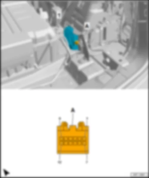
AUDI Q7 2016 Fitting location Control unit for overhead view camera J928
Fitting location Control unit for overhead view camera -J928- |
| On left in luggage compartment, behind the side trim, under the comfort system central control unit -J393- . |
| 1 - | Control unit for overhead view camera -J928- |
| B - | 5-pin connector -T5ap- , brown |
| q | to control unit for information electronics 1 -J794- |
| D - | 5-pin connector -T5ar- , black |
| q | to right overhead view camera -R245- |
| F - | 5-pin connector -T5at- , blue |
| q | to rear overhead view camera -R246- |
| Connector assignment, control unit for overhead view camera -J928- |
| -T18e- (A) | Designation | | -T18e- (A) | Designation | | -T18e- (A) | Designation |
| 1 | Terminal 30, from fuse carrier 3 -ST3- in fuse holder F -SF- | | 7 | | | 13 | |
| 2 | Extended high CAN bus, from B670 connection 3 (extended high CAN bus) in main wiring harness
Data bus diagnostic interface -J533- | | 8 | | | 14 | |
| 3 | | | 9 | | | 15 | |
| 4 | | | 10 | Extended CAN bus, low, from B671 connection 3 (extended CAN bus, low) in main wiring harness
Data bus diagnostic interface -J533- | | 16 | |
| 5 | | | 11 | | | 17 | |
| 6 | | | 12 | Terminal 31, to 387 earth connection 22 in main wiring harness
385 Earth connection 20 in main wiring harness
676 Earth point 2 on left in luggage compartment | | 18 | |
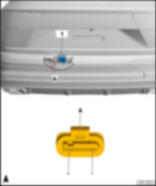
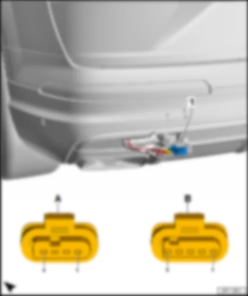
AUDI Q7 2016 Fitting location, rear lid power opening control unit J938
Fitting location, rear lid power opening control unit -J938- |
| on centre left at bottom on rear bumper cover. |
| 1 - | Rear lid power opening control unit -J938- |
| B - | 5-pin connector -T5bd- , black |
| Connector assignment, rear lid power opening control unit -J938- |
| -T4bs- (A) | Designation | | -T5bd- (B) | Designation |
| 1 | Terminal 30, from coupling point at right on rear bumper -TSFHR-
Convenience system central control unit -J393- | | 1 | Rear lid power opening sender -G750- |
| 2 | Terminal 31, to coupling point at right on rear bumper -TSFHR-
387 Earth connection 22 in main wiring harness
385 Earth connection 20 in main wiring harness
667 Earth point on rear left of roof | | 2 | Rear lid power opening sender -G750- |
| 3 | LIN bus, from coupling point at right on rear bumper -TSFHR-
Convenience system central control unit -J393- | | 3 | |
| 4 | | | 4 | Rear lid power opening sender 2 -G760- |
| | | | 5 | Rear lid power opening sender 2 -G760- |
AUDI Q7 2016 Fitting location, engine sound generator control unit J943
Fitting location, engine sound generator control unit -J943- |
| on right in luggage compartment, behind side trim, on wheel housing. |
| 1 - | Engine sound generator control unit -J943- |
| Connector assignment, engine sound generator control unit -J943- |
| -T2ap- (A) | Designation | | -T6f- (B) | Designation |
| 1 | Terminal 15, from fuse carrier 4 -ST4- in fuse holder B -SB- | | 7 | Terminal 15, from fuse carrier 4 -ST4- in fuse holder B -SB- |
| 2 | Terminal 31, to 676 earth point 2 on left in luggage compartment | | 8 | Terminal 31, to 676 earth point 2 on left in luggage compartment |
| 3 | Actuator 1 for engine sound generator -R257- | | 9 | |
| 4 | Actuator 1 for engine sound generator -R257- | | 10 | |
| 5 | | | 11 | Extended low CAN bus, to B671 connection 3 (extended low CAN bus) in main wiring harness |
| 6 | | | 12 | Extended high CAN bus, to B670 connection 3 (extended high CAN bus) in main wiring harness |
AUDI Q7 2016 Fitting location Rear-axle steering control unit J1019
Fitting location Rear-axle steering control unit -J1019- |
| On rear axle assembly carrier. |
| 1 - | Rear wheel steering control unit -J1019- |
| B - | 6-pin connector -T6f- |
| Connector assignment of rear-axle steering control unit -J1019- |
| -T2ap- (A) | Designation | | -T6f- (B) | Designation |
| 1 | Terminal 30, from fuse 6 -S139- in wiring junction -TV1-1)
Fuse 4 (30) -S207- in wiring junction 3 for terminal 30 -TV28-2) | | 1 | FlexRay bus, from coupling point on left in luggage compartment -THRL-
Data bus diagnostic interface -J533-3)
All-wheel drive control unit -J492-4) |
| 2 | Terminal 31, to 729 earth point on rear left wheel housing | | 2 | |
| | | | 3 | |
| | | | 4 | FlexRay bus, from coupling point on left in luggage compartment -THRL-
Data bus diagnostic interface -J533-3)
All-wheel drive control unit -J492-4) |
| | | | 5 | |
| | | | 6 | |
| 1) models without high-voltage system |
| 2) models with high-voltage system |
| 3) Only models without all-wheel drive control unit -J492- |
| 4) Only models with all-wheel drive control unit -J492- |
AUDI Q7 2016
Fitting location, CD changer -R41- /DVD changer -R161- |
| on left in luggage compartment, behind side trim, on wheel housing |
| 1 - | CD changer -R41- /DVD changer -R161- |
| B - | 2-pin connector -T2ev- , black |
| Connector assignment, CD changer -R41- /DVD changer -R161- |
| -T10l- (A) | Designation | | -T10l- (A) | Designation |
| 1 | | | 6 | |
| 2 | | | 7 | |
| 3 | Ring circuit break diagnostic | | 8 | |
| 4 | | | 9 | |
| 5 | Terminal 30, from fuse carrier 3 -ST3- in fuse holder F -SF- | | 10 | Terminal 31, to 387 earth connection 22 in main wiring harness
385 Earth connection 20 in main wiring harness
676 Earth point 2 on left in luggage compartment |
AUDI Q7 2016 Fitting location, remote control receiver for auxiliary heater R64
Fitting location, remote control receiver for auxiliary heater -R64- |
| on right in luggage compartment, behind the side trim. |
| 1 - | Remote control receiver for auxiliary heater -R64- |
| B - | 6-pin connector -T6e- , blue |
| Connector assignment, remote control receiver for auxiliary heater -R64- | | | |
| -T6e- (A) | Designation |
| 1 | Terminal 31, to 389 earth connection 24 in main wiring harness
51 Earth point on right in luggage compartment |
| 2 | Terminal 30, from fuse carrier 3 -ST3- in fuse holder F -SF- |
| 3 | |
| 4 | |
| 5 | Auxiliary heater control unit -J364- |
| 6 | |
AUDI Q7 2016 Fitting location TV tuner R78
Fitting location TV tuner -R78- |
| on right in luggage compartment, behind side trim, on wheel housing |
| B - | 2-pin connector -T2be- , black |
| D - | 4-pin connector -T4n- , green |
| q | from aerial amplifier 2 -R111- for aerial 2 for TV -R56- and aerial amplifier 1 for TV -R82- for aerial 3 for TV -R57- |
| Connector assignment, TV tuner -R78- |
| -T12h- (A) | Designation | | -T12h- (A) | Designation |
| 1 | Terminal 30, from fuse carrier 3 -ST3- in fuse holder F -SF- | | 7 | |
| 2 | Terminal 31, to 51 earth point on right in luggage compartment | | 8 | |
| 3 | Ring circuit break diagnostic | | 9 | |
| 4 | | | 10 | |
| 5 | | | 11 | |
| 6 | | | 12 | |
AUDI Q7 2016 Fitting location, aerial amplifier for mobile telephone R86
Fitting location, aerial amplifier for mobile telephone -R86- |
| on right in luggage compartment, behind the side trim. |
| 1 - | Aerial amplifier for mobile telephone -R86- |
| B - | 4-pin connector -T4fk- , black |
| Connector assignment, aerial amplifier for mobile telephone -R86- |
| | | -T4fk- (B) | Designation |
| 1 | Terminal 30, from fuse carrier 3 -ST3- in fuse holder F -SF- |
| 2 | Terminal 31, to 399 earth connection 34 in main wiring harness
51 Earth point on right in luggage compartment |
| 3 | Control unit 1 for information electronics -J794- |
| 4 | |
AUDI Q7 2016 Fitting location, high-voltage battery charging socket 1 UX4
Fitting location, high-voltage battery charging socket 1 -UX4- |
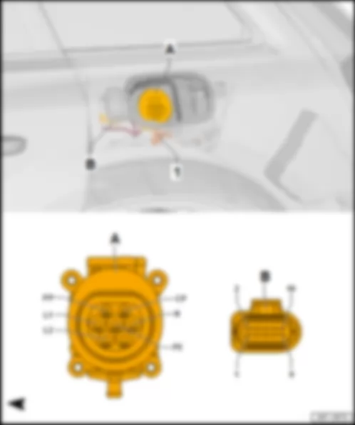
| In side part on left above the wheel housing. |
| 1 - | High-voltage wire for charging socket |
| A - | High-voltage battery charging socket 1 -UX4- |
| q | with actuator for high-voltage charging socket lock 1 -F498- and temperature sender for charging socket 1 -G853- |
| B - | Coupling point in luggage compartment, left -THRL- |
| q | 10-pin connector -T10ad- , black, to charging unit 1 for high-voltage battery -AX4- |
| q | 10-pin connector -T10adx- , black, to high-voltage battery charging socket 1 -UX4- |
| Connector assignment, coupling point in luggage compartment, left -THRL- to high-voltage battery charging socket 1 -UX4- |
| -T10adx- (A) | Designation | | -T10adx- (A) | Designation |
| 1 | High-voltage battery charging socket 1 -UX4- | | 6 | |
| 2 | High-voltage battery charging socket 1 -UX4- | | 7 | Actuator for high-voltage charging socket lock 1 -F498- |
| 3 | Temperature sender for charging socket 1 -G853- | | 8 | Actuator for high-voltage charging socket lock 1 -F498- |
| 4 | Temperature sender for charging socket 1 -G853- | | 9 | Actuator for high-voltage charging socket lock 1 -F498- |
| 5 | High-voltage battery charging socket 1 -UX4-1) 2) | | 10 | Actuator for high-voltage charging socket lock 1 -F498- |
| 1) for models with Japan equipment only |
| 2) for models for American markets only |

