AUTOMOTIVE ELECTRICIANS PORTAL

AUDI Q7 2017 – Adaptive cruise control . Wiring diagrams, Pin Connector, Location

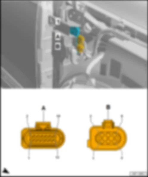
Wiring Diagram AUDI Q7 2017 - Adaptive cruise control unit - Control unit 2 for adaptive cruise control


Wiring Diagram  AUDI Q7 2017 - Adaptive cruise control unit - Control unit 2 for adaptive cruise control https://portal-diagnostov.com/license.html
https://portal-diagnostov.com/license.html Automotive Electricians Portal FZCO Automotive Electricians Portal FZCO
Download PDF file
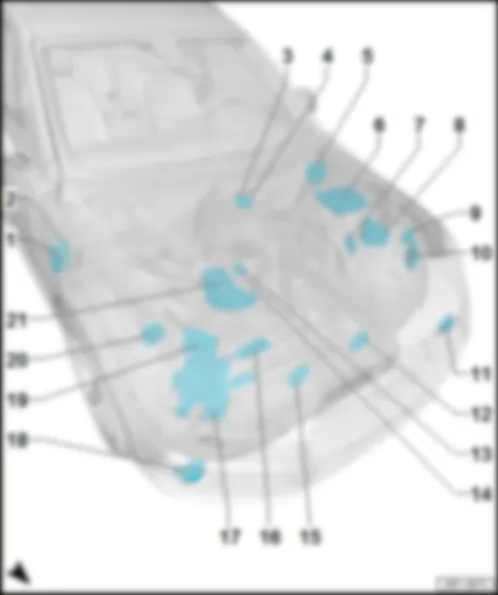
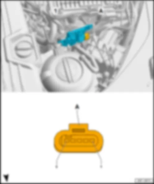
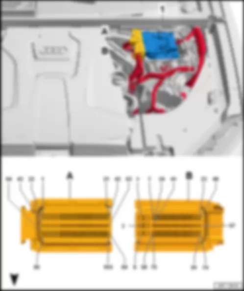
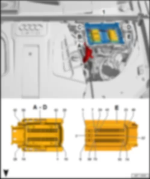
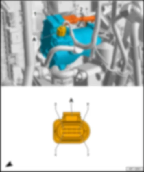
J428 Adaptive cruise control unit
J533 Data bus diagnostic interface
J850 Control unit 2 for adaptive cruise control
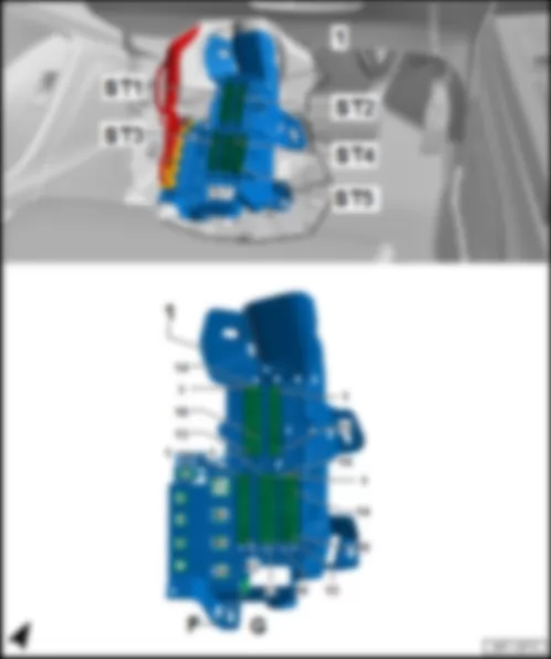
SB Fuse holder B
ST4 Fuse carrier 4
SB9 Fuse 9 on fuse holder B
T8d 8-pin connector, black
T8e 8-pin connector, black
T14b 14-pin connector
T14bx 14-pin connector
T54a 54-pin connector, black
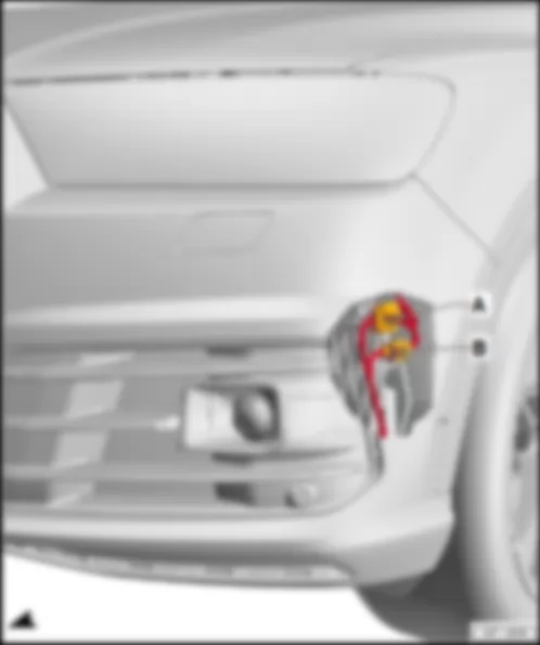
TSFVL Coupling point on front left bumper
   151 Earth connection 1, in front wiring harness
   373 Earth connection 8, in main wiring harness
   376 Earth connection 11, in main wiring harness
   C45 Positive connection 1 (15), in front wiring harness
*see applicable current flow diagram for fuse assignment
*2Data bus wire (FlexRay bus)


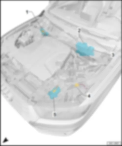
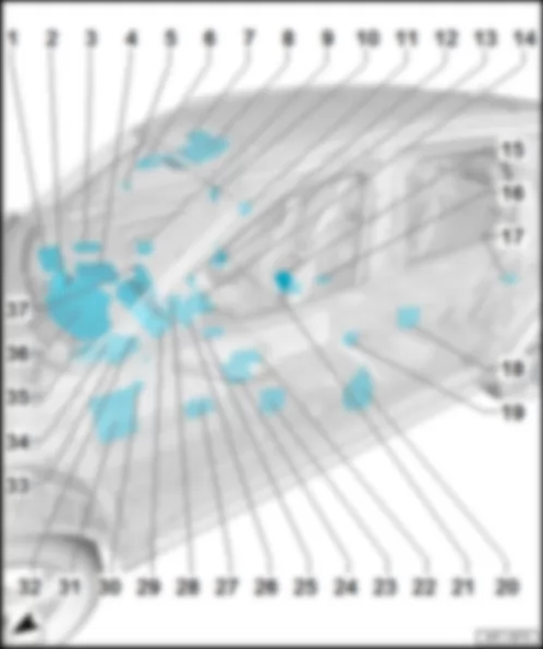
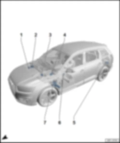
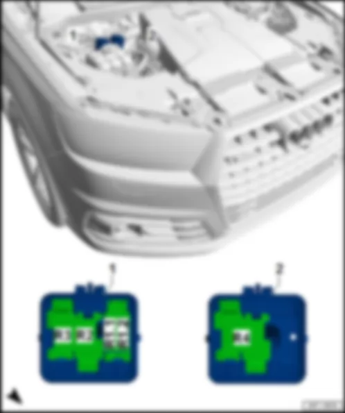
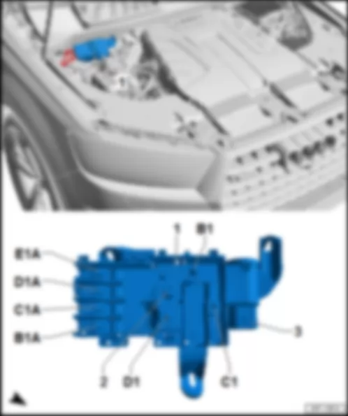
AUDI Q7 2017 Overview of control units in front part of vehicle

Overview of control units in front part of vehicle
AUDI Q7 2017 Overview of control units in front part of vehicle https://portal-diagnostov.com/license.html
https://portal-diagnostov.com/license.html Automotive Electricians Portal FZCO Automotive Electricians Portal FZCO
Get access to all wiring diagrams of the carDownload PDF file
q   Connector assignment
q   Fitting location for models with high-voltage system
q   Connector assignment
on front left headlight -MX1-
q   Fitting location, bi-xenon
q   Fitting location LED, LED matrix beam
q   Connector assignment, bi-xenon
q   Connector assignment, LED
q   Connector assignment, LED matrix beam
10 -  Output module 1 for left LED headlight -A31-
q   on front left headlight -MX1-
q   only installed on models with LED and LED matrix beam
q   Fitting location
q   Connector assignment, LED
q   Connector assignment, LED matrix beam
q   Connector assignment
on front right headlight -MX2-
q   only installed on models with LED and LED matrix beam
q   Fitting location
q   Connector assignment, LED
q   Connector assignment, LED matrix beam
20 -  Right light control unit -J1023-
q   on front right headlight -MX2-
q   Fitting location, bi-xenon
q   Fitting location LED, LED matrix beam
q   Connector assignment, bi-xenon
q   Connector assignment, LED
q   Connector assignment, LED matrix beam
q   Connector assignment


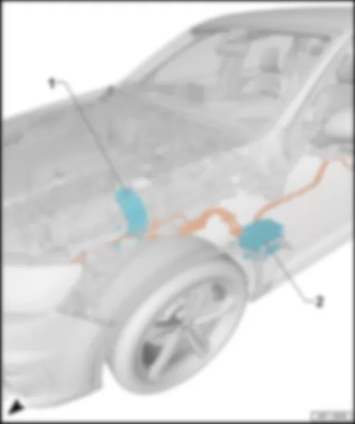
AUDI Q7 2017 Overview of additional control units in front part of vehicle for models with high-voltage system

Overview of additional control units in front part of vehicle for models with high-voltage system
AUDI Q7 2017 Overview of additional control units in front part of vehicle for models with high-voltage system https://portal-diagnostov.com/license.html
https://portal-diagnostov.com/license.html Automotive Electricians Portal FZCO Automotive Electricians Portal FZCO
Get access to all wiring diagrams of the carDownload PDF file
q   Connector assignment
Brake servo -NX6-
q   with brake pedal position sender -G100- /-G836- and brake servo control unit -J539-
q   Fitting location
q   Connector assignment


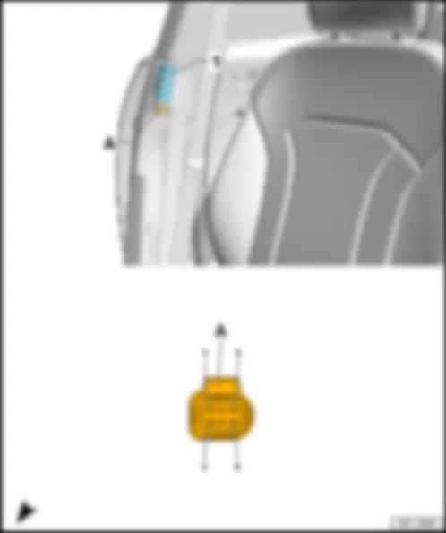
AUDI Q7 2017 Fitting location of particle sensor G784

Fitting location of particle sensor -G784-
Fitting location
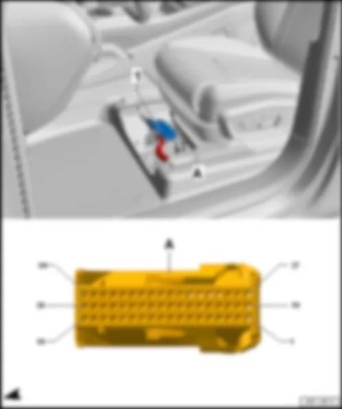
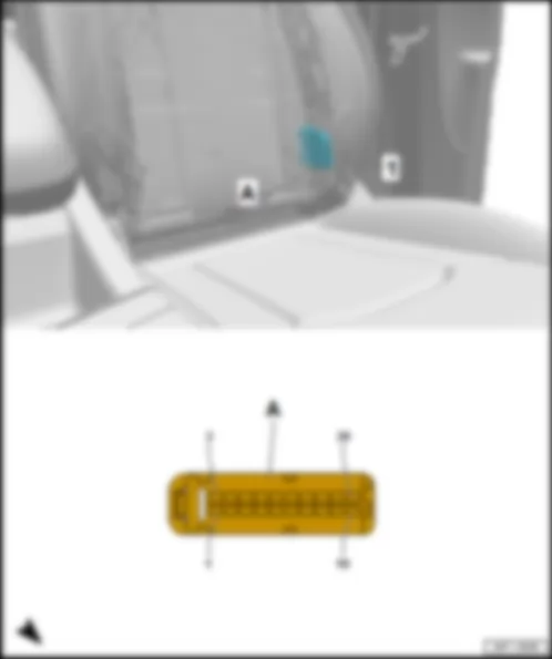
On left driver seat.
AUDI Q7 2017 Fitting location of particle sensor G784 https://portal-diagnostov.com/license.html
https://portal-diagnostov.com/license.html Automotive Electricians Portal FZCO Automotive Electricians Portal FZCO
Get access to all wiring diagrams of the carDownload PDF file
1 -  Particle sensor -G784-
Connector assignment particle sensor -G784-
   
-T4u- (A) Designation
1 Terminal 31, to 602 earth point on left in footwell
2 Drive low CAN bus, from B390 connection 1 (drive low CAN bus) in main wiring harness
Data bus diagnostic interface -J533-
3 Drive high CAN bus from B383 connection 1 (drive high CAN bus) in main wiring harness
Data bus diagnostic interface -J533-
4 Terminal 87, from B352 positive connection 3 (87a) in main wiring harness
Fuse carrier 1 -ST1- in fuse holder B -SB-

Back to overview .


AUDI Q7 2017 Fitting location, ABS control unit J104

Fitting location, ABS control unit -J104-
Fitting location
On left in engine compartment, in front of engine control unit -J623- .
AUDI Q7 2017 Fitting location, ABS control unit J104 https://portal-diagnostov.com/license.html
https://portal-diagnostov.com/license.html Automotive Electricians Portal FZCO Automotive Electricians Portal FZCO
Get access to all wiring diagrams of the carDownload PDF file
1 -  ABS control unit -J104-
q   with ABS hydraulic unit -N55-
Connector assignment, ABS control unit -J104-
-T46a- (A) Designation   -T46a- (A) Designation
1 Terminal 30, from fuse holder H -SH- in fuse holder B -SB- 24 Front left speed sensor -G47-
2 Right parking brake motor -V283- 25 Electromechanical parking brake warning lamp -K213-
3 Right parking brake motor -V283- 26 Front right speed sensor -G45-
4 Terminal 30, from fuse carrier 5 -ST5- in fuse holder B -SB- 27  
5   28 Data bus line (FlexRay bus), from engine control unit -J623-
6   29
7 Front left speed sensor -G47- 30 Terminal 30, from fuse holder H -SH- in fuse holder B -SB-
8 Roof carrier detection sensor -G625- 31 Electromechanical parking brake button -E538-
9   32 Electromechanical parking brake button -E538-
10   33
11   34
12 Left parking brake motor -V282- 35
13 Left parking brake motor -V282- 36 Terminal 15, from B281 positive connection 5 (15a) in main wiring harness
Onboard supply control unit -J519-
14 Terminal 31, to 671 earth point 1 on front side member, left 37 Rear right speed sensor -G44-
15 Electromechanical parking brake button -E538-   38  
16 Electromechanical parking brake button -E538-   39 Rear left speed sensor -G46-
17     40 Vacuum sender -G608-
18 Roof carrier detection sensor -G625-   41 Vacuum sender -G608-
19     42
20     43
21 Front right speed sensor -G45- 44 Data bus line (FlexRay bus), from engine control unit -J623-
22 Rear right speed sensor -G44- 45 Vacuum sender -G608-
23 Rear left speed sensor -G46- 46 Terminal 31, to 671 earth point 1 on front side member, left

Back to overview .


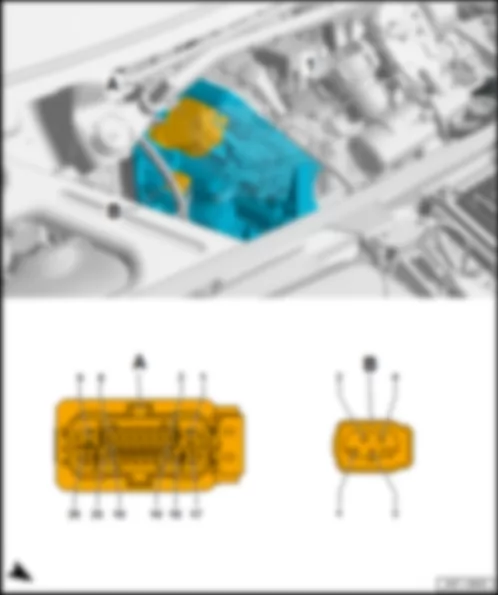
AUDI Q7 2017 Fitting location automatic glow period control unit J179

Fitting location automatic glow period control unit -J179-
Fitting location
At centre in plenum chamber.
AUDI Q7 2017 Fitting location automatic glow period control unit J179 https://portal-diagnostov.com/license.html
https://portal-diagnostov.com/license.html Automotive Electricians Portal FZCO Automotive Electricians Portal FZCO
Get access to all wiring diagrams of the carDownload PDF file
1 -  Automatic glow period control unit -J179-
2 -  Not installed
B -  Not installed

   
Connector assignment of automatic glow period control unit -J179-
-T11a- (A) Designation   -T11a- (B) Designation
1 Glow plug 1 -Q10-   7 Terminal 31, to 368 earth connection 3 in main wiring harness
655 Earth point, on left headlight
2 Glow plug 2 -Q11-   8 Glow plug 6 -Q15-
3 Glow plug 3 -Q12-   9  
4 Glow plug 4 -Q13-   10 Engine control unit -J623-
5 Glow plug 5 -Q14-   11 Terminal 30, from glow plug fuse -S125- in terminal 30 wiring junction 2 -TV22-
6 Terminal 87, from B466 connection 2 in main wiring harness
Fuse carrier 1 -ST1- in fuse holder B -SB-
     

Back to overview .


AUDI Q7 2017 Fitting location automatic gearbox control unit J217

Fitting location automatic gearbox control unit -J217-
Fitting location
Integrated in gearbox.
AUDI Q7 2017 Fitting location automatic gearbox control unit J217 https://portal-diagnostov.com/license.html
https://portal-diagnostov.com/license.html Automotive Electricians Portal FZCO Automotive Electricians Portal FZCO
Get access to all wiring diagrams of the carDownload PDF file
1 -  Automatic gearbox control unit -J217-
Connector assignment of automatic gearbox control unit -J217-
-T16a- (A) Designation   -T16a- (A) Designation
1 Selector position P/N line, to D217 connection (selector position P/N) in main wiring harness   9 Terminal 15, from B281 positive connection 5 (15a) in main wiring harness
2     10  
3 Data bus line (FlexRay bus), from data bus diagnostic interface -J533- 11  
4 Data bus line (FlexRay bus), from data bus diagnostic interface -J533- 12  
5 Data bus line (FlexRay bus), to power steering control unit -J500-1)
Brake servo -NX6-2)
  13 Terminal 30, fromfuse carrier 1 -ST1- in fuse holder F -SF-
6 Data bus line (FlexRay bus), to power steering control unit -J500-1)
Brake servo -NX6-2)
  14 Terminal 31, to 602 earth point on left in footwell
7     15 Gearbox oil cooling valve -N509-
8     16  

1) models without high-voltage system
2) models with high-voltage system
Back to overview .


AUDI Q7 2017

Fitting location, radiator fan control unit -J293- /-J671-
Fitting location
On radiator.
AUDI Q7 2017 https://portal-diagnostov.com/license.html
https://portal-diagnostov.com/license.html Automotive Electricians Portal FZCO Automotive Electricians Portal FZCO
Get access to all wiring diagrams of the carDownload PDF file
1 -  Radiator fan control unit 2 -J671-
2 -  Radiator fan control unit -J293-
B -  4-pin connector -T4w- , black

   
Connector assignment, radiator fan control unit -J293- /-J671-
-T4y- (A) Designation   -T4w- (B) Designation
1 Terminal 30, from radiator fan fuse for 2nd speed -S104- in terminal 30 wiring junction 2 -TV22-   1 Terminal 30, from B467 connection 3 in main wiring harness
Radiator fan single fuse -S42- in terminal 30 wiring junction 2 -TV22-
2 Terminal 87, from fuse carrier 1 -ST1- in fuse holder B -SB-1)
Thermal management control unit -J1024-2)
  2 Terminal 87, from fuse carrier 1 -ST1- in fuse holder B -SB-1)
Thermal management control unit -J1024-2)
3 Fan stage, from engine control unit -J623-1)
Thermal management control unit -J1024-2)
3 Fan stage, from engine control unit -J623-1)
Thermal management control unit -J1024-2)
4 Terminal 31, to 686 earth point 2 on front of right side member 4 Terminal 31, to 686 earth point 2 on front of right side member

1) models without high-voltage system
2) models with high-voltage system
Back to overview .


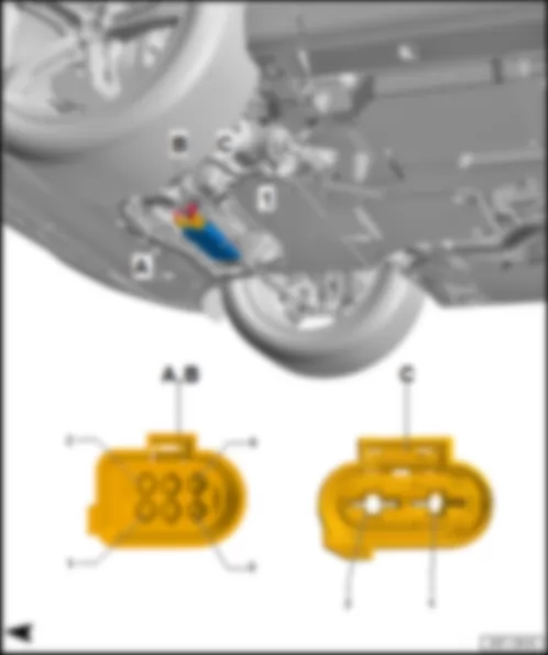
AUDI Q7 2017 Fitting location, auxiliary heater control unit J364

Fitting location, auxiliary heater control unit -J364-
Fitting location
In front right wheel housing on side member.
AUDI Q7 2017 Fitting location, auxiliary heater control unit J364 https://portal-diagnostov.com/license.html
https://portal-diagnostov.com/license.html Automotive Electricians Portal FZCO Automotive Electricians Portal FZCO
Get access to all wiring diagrams of the carDownload PDF file
1 -  Auxiliary heater control unit -J364-
B -  2-pin connector -T2ag- , brown
Connector assignment, auxiliary heater control unit -J364-
-T6c- (A) Designation   -T2ag- (B) Designation
1 Extended high CAN bus, from B670 connection 3 (extended high CAN bus) in main wiring harness
Data bus diagnostic interface -J533-
  1 Terminal 30 from fuse carrier 3 -ST3- in fuse holder B -SB-
2 Extended CAN bus, low, from B671 connection 3 (extended CAN bus, low) in main wiring harness
Data bus diagnostic interface -J533-
  2 Terminal 31, to 656 earth point on right headlight
3 Heater coolant shut-off valve -N279-      
4 Metering pump -V54-      
5 Terminal 31, to 380 earth connection 15 in main wiring harness
377 Earth connection 12 in main wiring harness
656 Earth point, on right headlight
     
6 Remote control receiver for auxiliary heater -R64-  

Back to overview .


AUDI Q7 2017 Fitting location, control unit for wiper motor J400

Fitting location, control unit for wiper motor -J400-
Fitting location
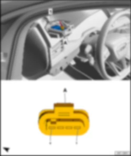
In driver side plenum chamber.
AUDI Q7 2017 Fitting location, control unit for wiper motor J400 https://portal-diagnostov.com/license.html
https://portal-diagnostov.com/license.html Automotive Electricians Portal FZCO Automotive Electricians Portal FZCO
Get access to all wiring diagrams of the carDownload PDF file
1 -  Wiper motor control unit -J400-
Connector assignment, wiper motor control unit -J400-
   
-T4fr- (A) Designation
1 Terminal 30, from fuse carrier 3 -ST3- in fuse holder B -SB-
2 Terminal 31, to 376 earth connection 11 in main wiring harness
655 Earth point, on left headlight
3  
4 LIN bus, from onboard supply control unit -J519-

Back to overview .


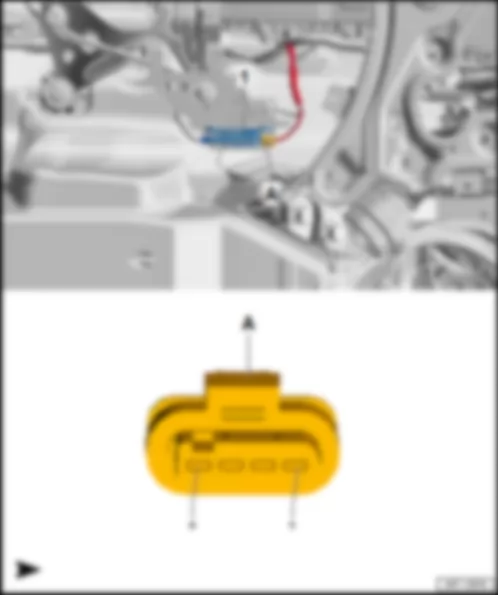
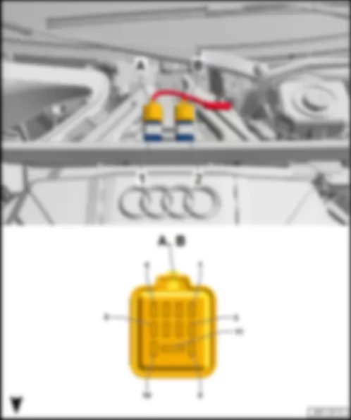
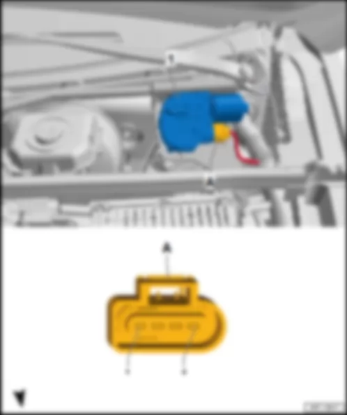
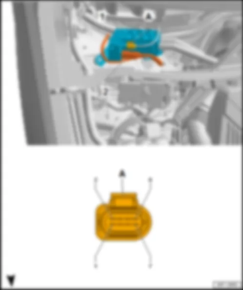
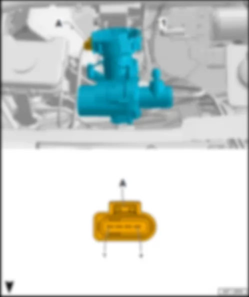
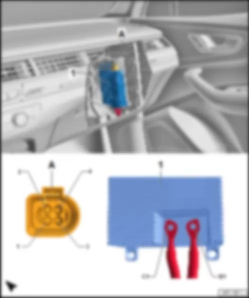
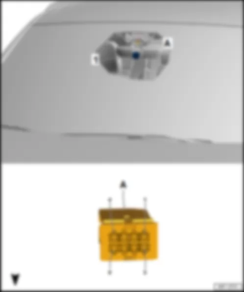
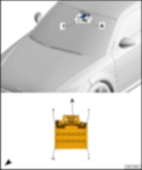
AUDI Q7 2017 Fitting location, adaptive cruise control unit J428

Fitting location, adaptive cruise control unit -J428-
Fitting location
On front right lock carrier behind the front bumper cover.
AUDI Q7 2017 Fitting location, adaptive cruise control unit J428 https://portal-diagnostov.com/license.html
https://portal-diagnostov.com/license.html Automotive Electricians Portal FZCO Automotive Electricians Portal FZCO
Get access to all wiring diagrams of the carDownload PDF file
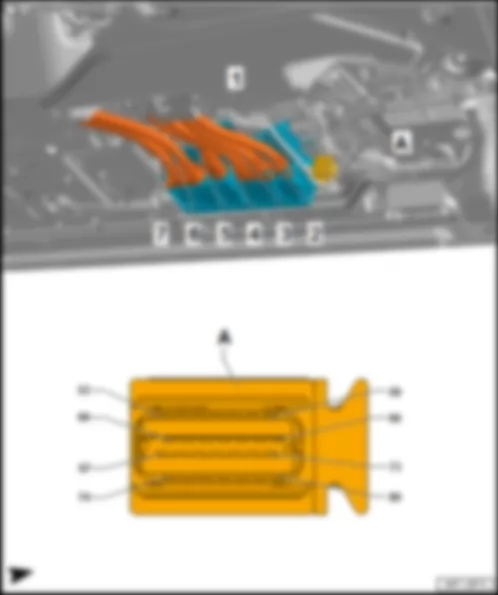
1 -  Adaptive cruise control unit -J428-
Connector assignment of adaptive cruise control unit -J428-
   
-T8e- (A) Designation
1 Terminal 31, to 151 earth connection 1 in front wiring harness
Coupling point on front left bumper -TSFVL-
373 Earth connection 8 in main wiring harness
376 Earth connection 11 in main wiring harness
655 Earth point, on left headlight
2  
3  
4  
5 Data bus line (FlexRay bus), from control unit 2 for adaptive cruise control -J850-
6 Data bus line (FlexRay bus), from control unit 2 for adaptive cruise control -J850-
7  
8 Terminal 15, from C45 positive connection 1 (15) in front wiring harness
Coupling point on front left bumper -TSFVL-
Fuse carrier 4 -ST4- in fuse holder B -SB-

Back to overview .


AUDI Q7 2017 Fitting location, power steering control unit J500

Fitting location, power steering control unit -J500-
Fitting location
On steering box.
AUDI Q7 2017 Fitting location, power steering control unit J500 https://portal-diagnostov.com/license.html
https://portal-diagnostov.com/license.html Automotive Electricians Portal FZCO Automotive Electricians Portal FZCO
Get access to all wiring diagrams of the carDownload PDF file
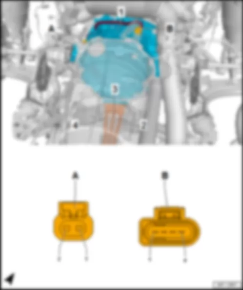
1 -  Power steering control unit -J500-
q   Components: steering moment sender -G269- , electromechanical power steering motor -V187-
B -  6-pin connector -T6aa- , brown
Connector assignment, power steering control unit -J500-
-T6aa- (B) Designation   -T2em- (C) Designation
1     1 Terminal 30, from fuse 1 -S131- in main fuse carrier on the battery1)
Fuse 3 (30) -S206- in wiring junction 3 for terminal 30 -TV28-2)
2 Terminal 15, from coupling point on left in engine compartment -TML-
B281 Positive connection 5 (15a) in main wiring harness
Onboard supply control unit -J519-
2 Terminal 31, to 745 earth point 3 on front of right side member
3 Data bus line (FlexRay bus), from automatic gearbox control unit -J217-1
Brake servo -NX6-2)
   
4        
5 Data bus line (FlexRay bus), from automatic gearbox control unit -J217-1
Brake servo -NX6-2)
     
6      

1) models without high-voltage system
2) models with high-voltage system
Back to overview .


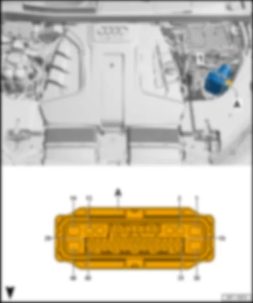
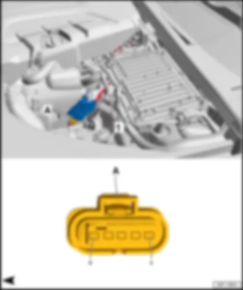
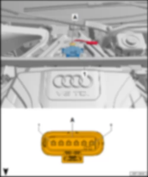
AUDI Q7 2017 Fitting location NOx sensor control unit J583

Fitting location NOx sensor control unit -J583-
   
Fitting location, NOx sensor control unit -J583- , models without high voltage system
Fitting location
On left in engine compartment at suspension turret.
AUDI Q7 2017 Fitting location NOx sensor control unit J583 https://portal-diagnostov.com/license.html
https://portal-diagnostov.com/license.html Automotive Electricians Portal FZCO Automotive Electricians Portal FZCO
Get access to all wiring diagrams of the carDownload PDF file
1 -  NOx sensor control unit -J583-
Connector assignment for NOx sensor control unit -J583-
   
-T5r- (A) Designation
1 Terminal 87, from B352 positive connection 3 (87a) in main wiring harness
Fuse carrier 1 -ST1- in fuse holder B -SB-
2 Terminal 31, to 373 earth connection 8 in main wiring harness
376 Earth connection 11 in main wiring harness
688 Earth point 2 on centre tunnel
3 Drive low CAN bus, from B394 connection 5 (drive low CAN bus) in main wiring harness
B390 Connection 1 (powertrain CAN bus, low), in main wiring harness
Data bus diagnostic interface -J533-
4 Drive high CAN bus from B387 connection 5 (drive high CAN bus) in main wiring harness
B383 Connection 1 (powertrain CAN bus, high), in main wiring harness
Data bus diagnostic interface -J533-
5  

Back to overview .
   
Fitting location, NOx sensor control unit -J583- , models with high voltage system
Fitting location
On left in engine compartment, in front of engine control unit -J623- .
AUDI Q7 2017 Fitting location NOx sensor control unit J583 https://portal-diagnostov.com/license.html
https://portal-diagnostov.com/license.html Automotive Electricians Portal FZCO Automotive Electricians Portal FZCO
Get access to all wiring diagrams of the carDownload PDF file
1 -  NOx sensor control unit -J583-
A -  5-pin connector -T5r- , black
q   Connector assignment

Fitting location, engine control unit -J623-
   
Fitting location, engine control unit -J623- , 196-pin
Fitting location
In left of engine compartment.
AUDI Q7 2017 Fitting location NOx sensor control unit J583 https://portal-diagnostov.com/license.html
https://portal-diagnostov.com/license.html Automotive Electricians Portal FZCO Automotive Electricians Portal FZCO
Get access to all wiring diagrams of the carDownload PDF file
1 -  Engine control unit -J623-
B -  91-pin connector -T91- , black

Back to overview .
   
Fitting location, engine control unit -J623- , 315-pin
Fitting location
In left of engine compartment.
AUDI Q7 2017 Fitting location NOx sensor control unit J583 https://portal-diagnostov.com/license.html
https://portal-diagnostov.com/license.html Automotive Electricians Portal FZCO Automotive Electricians Portal FZCO
Get access to all wiring diagrams of the carDownload PDF file
1 -  Engine control unit -J623-
B -  56-pin connector -T56b- , black
D -  56-pin connector -T56d- , black
E -  91-pin connector -T91- , black

Back to overview .


AUDI Q7 2017 Fitting location, control unit for air conditioning compressor J842

Fitting location, control unit for air conditioning compressor -J842-
Fitting location
In the electrical air conditioner compressor -V470- at front left on engine.
AUDI Q7 2017 Fitting location, control unit for air conditioning compressor J842 https://portal-diagnostov.com/license.html
https://portal-diagnostov.com/license.html Automotive Electricians Portal FZCO Automotive Electricians Portal FZCO
Get access to all wiring diagrams of the carDownload PDF file
1 -  Control unit for air conditioner compressor -J842-
A -  8-pin connector -T8an- , black

   
.


AUDI Q7 2017 Fitting location, high-voltage heater (PTC) control unit J848

Fitting location, high-voltage heater (PTC) control unit -J848-
Fitting location
In the high-voltage heater (PTC) -Z115- on right in plenum chamber.
AUDI Q7 2017 Fitting location, high-voltage heater (PTC) control unit J848 https://portal-diagnostov.com/license.html
https://portal-diagnostov.com/license.html Automotive Electricians Portal FZCO Automotive Electricians Portal FZCO
Get access to all wiring diagrams of the carDownload PDF file
1 -  High voltage heater (PTC) control unit -J848-
A -  8-pin connector -T8ao- , black

   
.


AUDI Q7 2017 Fitting location, control unit 2 for adaptive cruise control J850

Fitting location, control unit 2 for adaptive cruise control -J850-
Fitting location
On front left lock carrier behind the front bumper cover.
AUDI Q7 2017 Fitting location, control unit 2 for adaptive cruise control J850 https://portal-diagnostov.com/license.html
https://portal-diagnostov.com/license.html Automotive Electricians Portal FZCO Automotive Electricians Portal FZCO
Get access to all wiring diagrams of the carDownload PDF file
1 -  Control unit 2 for adaptive cruise control -J850-
Connector assignment of control unit 2 for adaptive cruise control -J850-
   
-T8d- (A) Designation
1 Terminal 31, to 151 earth connection 1 in front wiring harness
Coupling point on front left bumper -TSFVL-
373 Earth connection 8 in main wiring harness
376 Earth connection 11 in main wiring harness
655 Earth point, on left headlight
2 Data bus line (FlexRay bus), to control unit for adaptive cruise control -J428-
3 Data bus line (FlexRay bus), to control unit for adaptive cruise control -J428-
4  
5 Data bus line (FlexRay bus), from coupling point at left of front bumper -TSFVL-
Data bus diagnostic interface -J533-
6 Data bus line (FlexRay bus), from coupling point at left of front bumper -TSFVL-
Data bus diagnostic interface -J533-
7  
8 Terminal 15, from C45 positive connection 1 (15) in front wiring harness
Coupling point on front left bumper -TSFVL-
Fuse carrier 4 -ST4- in fuse holder B -SB-

Back to overview .


AUDI Q7 2017 Fitting location, control unit for structure-borne sound J869

Fitting location, control unit for structure-borne sound -J869-
Fitting location
At centre in plenum chamber.
AUDI Q7 2017 Fitting location, control unit for structure-borne sound J869 https://portal-diagnostov.com/license.html
https://portal-diagnostov.com/license.html Automotive Electricians Portal FZCO Automotive Electricians Portal FZCO
Get access to all wiring diagrams of the carDownload PDF file
1 -  Control unit for structure-borne sound -J869-
Connector assignment, control unit for structure-borne sound -J869-
   
-T6z- (A) Designation
1 Actuator for structure-borne sound -R214-
2 Actuator for structure-borne sound -R214-
3 Terminal 15, from B283 positive connection 7 (15a) in main wiring harness
Fuse carrier 4 -ST4- in fuse holder B -SB-
4 Terminal 31, to 201 earth connection 5 in engine compartment wiring harness
209 Earth connection 6 in engine compartment wiring harness
656 Earth point, on right headlight
5 Extended low CAN bus, to B671 connection 3 (extended low CAN bus) in main wiring harness
Data bus diagnostic interface -J533-
6 Extended high CAN bus, to B670 connection 3 (extended high CAN bus) in main wiring harness
Data bus diagnostic interface -J533-

Back to overview .


AUDI Q7 2017 Fitting location, control unit for NOx sender 2 J881

Fitting location, control unit for NOx sender 2 -J881-
Fitting location
On left driver seat.
AUDI Q7 2017 Fitting location, control unit for NOx sender 2 J881 https://portal-diagnostov.com/license.html
https://portal-diagnostov.com/license.html Automotive Electricians Portal FZCO Automotive Electricians Portal FZCO
Get access to all wiring diagrams of the carDownload PDF file
1 -  Control unit for NOx sender 2 -J881-
Connector assignment, control unit for NOx sender 2 -J881-
   
-T5s- (A) Designation
1 Terminal 87, from B352 positive connection 3 (87a) in main wiring harness
Fuse carrier 1 -ST1- in fuse holder B -SB-
2 Terminal 31, to 372 earth connection 7 in main wiring harness
381 Earth connection 16 in main wiring harness
720 Earth point, on right B-pillar
3 Drive low CAN bus, from B390 connection 1 (drive low CAN bus) in main wiring harness
Data bus diagnostic interface -J533-
4 Drive high CAN bus from B383 connection 1 (drive high CAN bus) in main wiring harness
Data bus diagnostic interface -J533-
5 Terminal 31, to 371 earth connection 6 in main wiring harness
379 Earth connection 14 in main wiring harness
79 Earth point, on left B-pillar

Back to overview .


AUDI Q7 2017 Fitting location, power unit mounting control unit J931

Fitting location, power unit mounting control unit -J931-
Fitting location
Under the wing, at the top on the right of the A-pillar.
AUDI Q7 2017 Fitting location, power unit mounting control unit J931 https://portal-diagnostov.com/license.html
https://portal-diagnostov.com/license.html Automotive Electricians Portal FZCO Automotive Electricians Portal FZCO
Get access to all wiring diagrams of the carDownload PDF file
1 -  Power unit mounting control unit -J931-
B -  6-pin connector -T6n- , black

   
Connector assignment, power unit mounting control unit -J931-
-T14g- (A) Designation   -T6n- (B) Designation
1 Power unit mounting sender 1 -G748-   1 Power unit mounting actuator 1 -N513-
2 Power unit mounting sender 1 -G748-   2 Power unit mounting actuator 1 -N513-
3 Power unit mounting sender 2 -G749-   3 Terminal 31, to 656 earth point on right headlight
4 Engine control unit -J623-   4 Power unit mounting actuator 2 -N514-
5     5 Power unit mounting actuator 2 -N514-
6 Power unit mounting sender 2 -G749- 6 Terminal 30, from fuse carrier 2 -ST2- in fuse holder B -SB-
7        
8        
9        
10 Hybrid CAN bus, high, to B776 connection 1 (hybrid CAN bus, high) in main wiring harness      
11        
12 Hybrid CAN bus, low, to B777 connection 1 (hybrid CAN bus, low) in main wiring harness      
13        
14 Terminal 15, from B281 positive connection 5 (15a) in main wiring harness      

Back to overview .


AUDI Q7 2017 Fitting location, thermal management control unit J1024

Fitting location, thermal management control unit -J1024-
Fitting location
Under the wing, at the top on the right of the A-pillar.
AUDI Q7 2017 Fitting location, thermal management control unit J1024 https://portal-diagnostov.com/license.html
https://portal-diagnostov.com/license.html Automotive Electricians Portal FZCO Automotive Electricians Portal FZCO
Get access to all wiring diagrams of the carDownload PDF file
1 -  Thermal management control unit -J1024-
Connector assignment, thermal management control unit -J1024-
-T40a- (A) Designation   -T40a- (A) Designation
81     101 Sender earth connection, to 285 earth connection 7 in interior wiring harness
82 Coolant temperature sender 3 for thermal management -G904-   102  
83 Coolant temperature sender 6 for thermal management -G907-   103 LIN bus, to B842 connection 8 (LIN bus) in main wiring harness
84 Coolant temperature sender 8 for thermal management -G968-   104 LIN bus, to B608 connection 4 in interior wiring harness
85     105 Hybrid CAN bus, high, to B776 connection 1 (hybrid CAN bus, high) in main wiring harness
86     106  
87 Thermal management coolant pump 2 -V618-   107 Thermal management coolant pump relay -J1141-
88 Radiator fan control unit 2 -J671-   108 Refrigerant shut-off valve -V424-
89 Radiator fan control unit 2 -J671-   109 Coolant changeover valve 1 -N632-
90     110 Coolant changeover valve 2 -N633-
91 Coolant temperature sender 5 for thermal management -G906-   111 Coolant changeover valve 3 -N634-
92 Coolant temperature sender 7 for thermal management -G908-   112 Coolant changeover valve 4 -N635-
93     113 Hybrid CAN bus, low, to B777 connection 1 (hybrid CAN bus, low) in main wiring harness
94 Thermal management coolant pump 4 -V620-   114 Sender earth connection, to 294 earth connection 9 in interior wiring harness
95 Thermal management coolant pump -V617-   115 Terminal 31, to 656 earth point on right headlight
96 Radiator fan control unit -J293-   116 Terminal 30, from fuse carrier 2 -ST2- in fuse holder B -SB-
97 Radiator fan control unit -J293-   117 Coolant shut-off valve 2 -N645-
98 Coolant temperature sender 1 for thermal management -G902-   118  
99 Coolant temperature sender 4 for thermal management -G905-   119  
100 Coolant shortage indicator sender 2 -G837-   120  

Back to overview .


AUDI Q7 2017

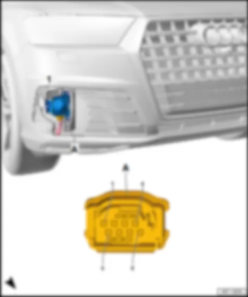
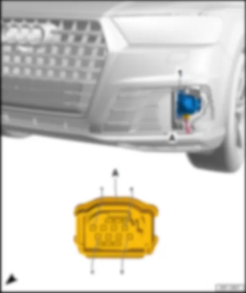
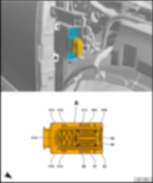
Fitting location, control units on front headlight -MX1- /-MX2-
   
Fitting location, control units on front headlight -MX1- /-MX2-
Fitting location
At front of vehicle.
  Note:
The fitting location of the left light control unit -J1018- is shown. The fitting location of the right light control unit -J1023- is laterally reversed.
AUDI Q7 2017 https://portal-diagnostov.com/license.html
https://portal-diagnostov.com/license.html Automotive Electricians Portal FZCO Automotive Electricians Portal FZCO
Get access to all wiring diagrams of the carDownload PDF file
1 -  Left light control unit -J1018- /right light control unit -J1023-
14-pin connector -T14d- /-T14e- , black
q   Left headlight: -T14d-
q   Right headlight: -T14e-

   
Connector assignment for headlight, bi-xenon
-T14d- (A) Designation   -T14e- (A) Designation
1 Extended CAN bus, high, to
Onboard supply control unit -J519-
  1 Extended CAN bus, high, to
Onboard supply control unit -J519-
2 Extended CAN bus, low, to
Onboard supply control unit -J519-
  2 Extended CAN bus, low, to
Onboard supply control unit -J519-
3     3
4 Onboard supply control unit -J519-   4 Onboard supply control unit -J519-
5 Terminal 31, to 376 earth connection 11 in main wiring harness
655 Earth point, on left headlight
  5 Terminal 31, to 377 earth connection 12 in main wiring harness
656 Earth point, on right headlight
6 Onboard supply control unit -J519- 6 Onboard supply control unit -J519-
7     7  
8     8  
9     9  
10 Terminal 31, to 376 earth connection 11 in main wiring harness
655 Earth point, on left headlight
  10 Terminal 31, to 377 earth connection 12 in main wiring harness
656 Earth point, on right headlight
11 Onboard supply control unit -J519-   11 Onboard supply control unit -J519-
12     12  
13     13  
14     14  

Back to overview .
   
Fitting location, control units on front headlight -MX1- /-MX2-
Fitting location
At front of vehicle.
  Note:
The fitting location of the control units at the left headlight -MX1- is shown. The fitting locations of the control units at the right headlight -MX2- are laterally reversed.
AUDI Q7 2017 https://portal-diagnostov.com/license.html
https://portal-diagnostov.com/license.html Automotive Electricians Portal FZCO Automotive Electricians Portal FZCO
Get access to all wiring diagrams of the carDownload PDF file
1 -  Output module 1 for left LED headlight -A31- /output module 1 for right LED headlight -A27-
2 -  Left light control unit -J1018- /right light control unit -J1023-
A -  14-pin connector -T14d- /-T14e- , black
q   Left headlight: -T14d-
q   Right headlight: -T14e-

   
Connector assignment for headlight, LED
-T14d- (A) Designation   -T14e- (A) Designation
1 Extended CAN bus, high, to
Onboard supply control unit -J519-
  1 Extended CAN bus, high, to
Onboard supply control unit -J519-
2 Extended CAN bus, low, to
Onboard supply control unit -J519-
  2 Extended CAN bus, low, to
Onboard supply control unit -J519-
3     3
4     4  
5 Terminal 31, to 376 earth connection 11 in main wiring harness
655 Earth point, on left headlight
  5 Terminal 31, to 377 earth connection 12 in main wiring harness
656 Earth point, on right headlight
6 Onboard supply control unit -J519- 6 Onboard supply control unit -J519-
7     7  
8 Terminal 15, from fuse carrier 4 -ST4- in fuse holder B -SB-   8 Terminal 15, from fuse carrier 4 -ST4- in fuse holder B -SB-
9 Onboard supply control unit -J519-   9 Onboard supply control unit -J519-
10 Terminal 31, to 376 earth connection 11 in main wiring harness
655 Earth point, on left headlight
  10 Terminal 31, to 377 earth connection 12 in main wiring harness
656 Earth point, on right headlight
11 Onboard supply control unit -J519-   11 Onboard supply control unit -J519-
12     12  
13     13  
14     14  

Back to overview .
   
Connector assignment for headlight, matrix beam
-T14d- (A) Designation   -T14e- (A) Designation
1 Extended CAN bus, high, to
B108 Connection 1 (CAN bus extended, high), in main wiring harness
Onboard supply control unit -J519-
Front camera for driver assist systems -R242-
  1 Extended CAN bus, high, to
Onboard supply control unit -J519-
2 Extended CAN bus, low, to
B109 Connection 1 (CAN bus extended, low), in main wiring harness
Onboard supply control unit -J519-
Front camera for driver assist systems -R242-
  2 Extended CAN bus, low, to
Onboard supply control unit -J519-
3     3
4     4  
5 Terminal 31, to 376 earth connection 11 in main wiring harness
655 Earth point, on left headlight
  5 Terminal 31, to 377 earth connection 12 in main wiring harness
656 Earth point, on right headlight
6 Onboard supply control unit -J519- 6 Onboard supply control unit -J519-
7 Terminal 31, to 376 earth connection 11 in main wiring harness
655 Earth point, on left headlight
  7 Terminal 31, to 377 earth connection 12 in main wiring harness
656 Earth point, on right headlight
8 Terminal 15, from fuse carrier 4 -ST4- in fuse holder B -SB-   8 Terminal 15, from fuse carrier 4 -ST4- in fuse holder B -SB-
9 Onboard supply control unit -J519-   9 Onboard supply control unit -J519-
10 Terminal 31, to 376 earth connection 11 in main wiring harness
655 Earth point, on left headlight
  10 Terminal 31, to 377 earth connection 12 in main wiring harness
656 Earth point, on right headlight
11 Onboard supply control unit -J519-   11 Onboard supply control unit -J519-
12     12  
13     13  
14     14  

Back to overview .
   
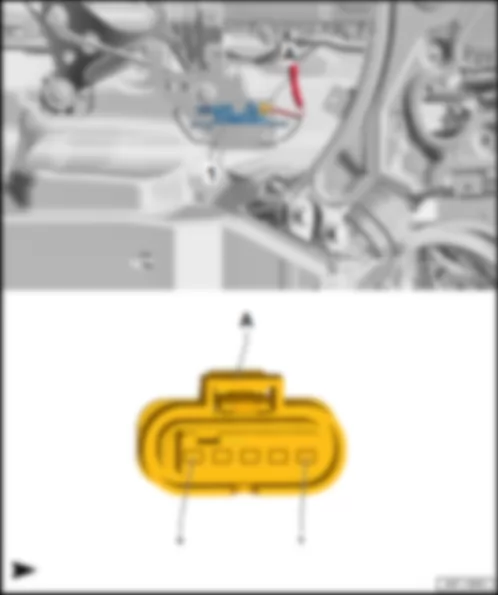
Fitting location, brake servo -NX6-
Fitting location
At centre left in plenum chamber
AUDI Q7 2017 https://portal-diagnostov.com/license.html
https://portal-diagnostov.com/license.html Automotive Electricians Portal FZCO Automotive Electricians Portal FZCO
Get access to all wiring diagrams of the carDownload PDF file
1 -  Brake servo -NX6-
q   with brake pedal position sender -G100- /-G836- and brake servo control unit -J539-
B -  4-pin connector -T4hf- , black
q   from brake pedal position sender -G100- /-G836- to brake servo control unit -J539-

   
.


AUDI Q7 2017 Fitting location maintenance connector for high-voltage system TW

Fitting location maintenance connector for high-voltage system -TW-
Fitting location
On the connecting plate above the front left headlight -MX1- .
AUDI Q7 2017 Fitting location maintenance connector for high-voltage system TW https://portal-diagnostov.com/license.html
https://portal-diagnostov.com/license.html Automotive Electricians Portal FZCO Automotive Electricians Portal FZCO
Get access to all wiring diagrams of the carDownload PDF file
1 -  Maintenance connector for high-voltage system -TW-
Connector assignment maintenance connector for high-voltage system -TW-
   
-T4hg- (A) Designation
1 Terminal 30, from fuse carrier 4 -ST4- in fuse holder F -SF-
2 Hybrid battery unit -AX1-
3 Control unit for air conditioning compressor -J842- (pilot line)
4 Hybrid battery unit -AX1- (pilot line)

Back to overview .


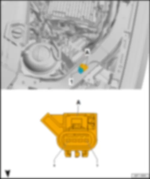
AUDI Q7 2017 Fitting location, brake system pressure accumulator VX70

Fitting location, brake system pressure accumulator -VX70-
Fitting location
In the plenum chamber on the left next to the brake servo -NX6- .
AUDI Q7 2017 Fitting location, brake system pressure accumulator VX70 https://portal-diagnostov.com/license.html
https://portal-diagnostov.com/license.html Automotive Electricians Portal FZCO Automotive Electricians Portal FZCO
Get access to all wiring diagrams of the carDownload PDF file
1 -  Brake system pressure accumulator -VX70-
Connector assignment of brake system pressure accumulator -VX70-
   
-T4hg- (A) Designation
1 Terminal 30, from fuse carrier 5 -ST5- in fuse holder B -SB-
2 Brake servo -NX6-
3 Brake servo -NX6-
4 Terminal 31, to 645 earth point 1 on bulkhead

Back to overview .


AUDI Q7 2017 Overview of control units in middle part of vehicle

Overview of control units in middle part of vehicle
AUDI Q7 2017 Overview of control units in middle part of vehicle https://portal-diagnostov.com/license.html
https://portal-diagnostov.com/license.html Automotive Electricians Portal FZCO Automotive Electricians Portal FZCO
Get access to all wiring diagrams of the carDownload PDF file
q   Connector assignment
q   Connector assignment of air conditioning system KH5
q   Fitting location of air conditioning system 9AH
q   Connector assignment of air conditioning system 9AH
q   Connector assignment
Rear information display and operating unit control unit -J648- /-J649-
q   Rear left information display and operating unit control unit -J648-
q   Rear right information display and operating unit control unit -J649-
q   Fitting location
q   Connector assignment, rear left information display and operating unit control unit -J648-
q   Connector assignment, rear right information display and operating unit control unit -J649-
q   Connector assignment
Seat and steering column adjustment control unit with memory -J136- /front passenger seat adjustment control unit with memory -J521-
q   Fitting location
q   Connector assignment, seat and steering column adjustment control unit with memory -J136-
q   Connector assignment, front passenger seat adjustment control unit with memory -J521-
q   Connector assignment
q   Fitting location, models with Audi connect emergency call & service (IW3)
q   Connector assignment, models without Audi connect emergency call & service (IW0)
q   Connector assignment, models with Audi connect emergency call & service (IW3)
q   Connector assignment
q   Connector assignment of air conditioning system 9AD
q   Connector assignment of air conditioning system KH5
q   Connector assignment of air conditioning system 9AH


AUDI Q7 2017 Overview of additional control units in centre part of vehicle for models with high-voltage system

Overview of additional control units in centre part of vehicle for models with high-voltage system
AUDI Q7 2017 Overview of additional control units in centre part of vehicle for models with high-voltage system https://portal-diagnostov.com/license.html
https://portal-diagnostov.com/license.html Automotive Electricians Portal FZCO Automotive Electricians Portal FZCO
Get access to all wiring diagrams of the carDownload PDF file
Three-phase current drive -VX54-
q   with drive motor temperature sender -G712- , drive motor rotor position sender 1 -G713- and electric drive motor -V141-
q   Fitting location
Power and control electronics for electric drive -JX1-
q   with voltage converter -A19- , DC/AC converter for drive motor -A37- and electric drive control unit -J841-
q   Fitting location
q   Connector assignment


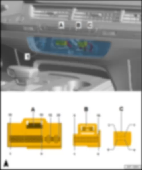
AUDI Q7 2017 Fitting location Operating and display unit for Climatronic air conditioning system E87

Fitting location Operating and display unit for Climatronic air conditioning system -E87-
Fitting location
in centre of dash panel.
AUDI Q7 2017 Fitting location Operating and display unit for Climatronic air conditioning system E87 https://portal-diagnostov.com/license.html
https://portal-diagnostov.com/license.html Automotive Electricians Portal FZCO Automotive Electricians Portal FZCO
Get access to all wiring diagrams of the carDownload PDF file
1 -  Operating and display unit for Climatronic air conditioning system -E87-
B -  16-pin connector -T16k- , black
Connector assignment of operating and display unit for Climatronic air conditioning system -E87- , air conditioning system 9AD
-T20d- (A) Designation   -T16k- (B) Designation
1   1 Rear temperature flap control motor -V137-
2 Drive high CAN bus, from coupling point at bottom on left A-pillar -TALU-
B385 Connection 3 (powertrain CAN bus, high), in main wiring harness
B384 Connection 2 (powertrain CAN bus, high), in main wiring harness
Data bus diagnostic interface -J533-
2 Terminal 30, to L5 connection 1 in air conditioner unit wiring harness
Defroster flap control motor -V107-
Rear temperature flap control motor -V137-
Left temperature flap control motor -V158-
Left side vent control motor -V299-
Right side vent control motor -V300-
L6 Connection 2 in air conditioning system wiring harness
Air recirculation flap control motor -V113-
Right temperature flap control motor -V159-
Rear air distribution flap control motor -V427-
Fresh air flap control motor -V438-
Auxiliary air heater control unit -J604-
3 Drive low CAN bus, from coupling point at bottom on left A-pillar -TALU-
B392 Connection 3 (powertrain CAN bus, low), in main wiring harness
B391 Connection 2 (powertrain CAN bus, low), in main wiring harness
Data bus diagnostic interface -J533-
3 Earth, to 112 earth connection 2 in air conditioning system wiring harness
Defroster flap control motor -V107-
Air recirculation flap control motor -V113-
Rear temperature flap control motor -V137-
Left temperature flap control motor -V158-
Right temperature flap control motor -V159-
Left side vent control motor -V299-
Right side vent control motor -V300-
Rear air distribution flap control motor -V427-
Fresh air flap control motor -V438-
4 LIN bus, to A227 connection 2 (LIN bus) in dash panel wiring harness
Fresh air blower control unit -J126-
Coupling point on left A-pillar, bottom -TALU-
B698 Connection 3 (LIN bus) in main wiring harness
High-pressure sender -G65-
Humidity sender in fresh air intake duct -G657- , air quality sensor -G238-
4 Evaporator output temperature sender -G263-
5   5 Left footwell vent temperature sender -G261-
6 Photosensor for sunlight intensity -G107- 6 Right footwell vent temperature sender -G262-
7 Earth, to 335 earth connection 5 in dash panel wiring harness
Photosensor for sunlight intensity -G107-
Front left chest vent temperature sensor -G385-
Front right chest vent temperature sensor -G386-
Coupling point on left A-pillar, bottom -TALU-
Rear chest vent temperature sensor -G537-
7  
8 Photosensor for sunlight intensity -G107- 8
9 Photosensor for sunlight intensity -G107- 9 Earth, to 97 earth connection 1 in air conditioning system wiring harness
Left footwell vent temperature sender -G261-
Right footwell vent temperature sender -G262-
Evaporator output temperature sender -G263-
10   10
11 Front left chest vent temperature sensor -G385- 11 Auxiliary air heater control unit -J604-
12 Front right chest vent temperature sensor -G386- 12  
13   13
14   14
15 Rear chest vent temperature sensor -G537-   15  
16 Terminal 30, to coupling point at bottom on left A-pillar -TALU-
B487 connection 23 in main wiring harness
High-pressure sender -G65-
Humidity sender in fresh air intake duct -G657- , air quality sensor -G238-
  16  
17      
18      
19 Terminal 31, to 752 earth point 3 on right A-pillar1)
687 Earth point 1 on centre tunnel2)
 
20 Terminal 30, from fuse holder C -SC-    

1) Left-hand drive
2) Right-hand drive
Back to overview .
   
Connector assignment of operating and display unit for Climatronic air conditioning system -E87- , air conditioning system KH5
-T20d- (A) Designation   -T16k- (B) Designation
1   1 Rear temperature flap control motor -V137-
2 Drive high CAN bus, from coupling point at bottom on left A-pillar -TALU-
B385 Connection 3 (powertrain CAN bus, high), in main wiring harness
B384 Connection 2 (powertrain CAN bus, high), in main wiring harness
Data bus diagnostic interface -J533-
2 Terminal 30, to L5 connection 1 in air conditioner unit wiring harness
Defroster flap control motor -V107-
Rear temperature flap control motor -V137-
Left temperature flap control motor -V158-
Left side vent control motor -V299-
Right side vent control motor -V300-
L6 Connection 2 in air conditioning system wiring harness
Air recirculation flap control motor -V113-
Right temperature flap control motor -V159-
Rear air distribution flap control motor -V427-
Fresh air flap control motor -V438-
Auxiliary air heater control unit -J604-
3 Drive low CAN bus, from coupling point at bottom on left A-pillar -TALU-
B392 Connection 3 (powertrain CAN bus, low), in main wiring harness
B391 Connection 2 (powertrain CAN bus, low), in main wiring harness
Data bus diagnostic interface -J533-
3 Earth, to 112 earth connection 2 in air conditioning system wiring harness
Defroster flap control motor -V107-
Air recirculation flap control motor -V113-
Rear temperature flap control motor -V137-
Left temperature flap control motor -V158-
Right temperature flap control motor -V159-
Left side vent control motor -V299-
Right side vent control motor -V300-
Rear air distribution flap control motor -V427-
Fresh air flap control motor -V438-
4 LIN bus, to A227 connection 2 (LIN bus) in dash panel wiring harness
Fresh air blower control unit -J126-
Coupling point on left A-pillar, bottom -TALU-
B698 Connection 3 (LIN bus) in main wiring harness
Rear Climatronic operating and display unit -E265-
High-pressure sender -G65-
Humidity sender in fresh air intake duct -G657- , air quality sensor -G238-
Coupling point in interior, centre -TIM-
Rear fresh air blower control unit -J391-
Rear right chest vent control motor -V316-
4 Evaporator output temperature sender -G263-
5   5 Left footwell vent temperature sender -G261-
6 Photosensor for sunlight intensity -G107- 6 Right footwell vent temperature sender -G262-
7 Earth, to 335 earth connection 5 in dash panel wiring harness
Photosensor for sunlight intensity -G107-
Front left chest vent temperature sensor -G385-
Front right chest vent temperature sensor -G386-
7  
8 Photosensor for sunlight intensity -G107- 8
9 Photosensor for sunlight intensity -G107- 9 Earth, to 97 earth connection 1 in air conditioning system wiring harness
Left footwell vent temperature sender -G261-
Right footwell vent temperature sender -G262-
Evaporator output temperature sender -G263-
10   10
11 Front left chest vent temperature sensor -G385- 11 Auxiliary air heater control unit -J604-
12 Front right chest vent temperature sensor -G386- 12  
13   13
14   14
15     15
16 Terminal 30, to coupling point at bottom on left A-pillar -TALU-
B487 connection 23 in main wiring harness
High-pressure sender -G65-
Humidity sender in fresh air intake duct -G657- , air quality sensor -G238-
Coupling point in interior, centre -TIM-
L31 Connection (5 volt) in air conditioning unit wiring harness
Right B-pillar and footwell shut-off flap control motor -V211-
Left B-pillar and footwell shut-off flap control motor -V212-
Rear left chest vent control motor -V315-
Rear right chest vent control motor -V316-
  16
17 Earth, to coupling point on right A-pillar, bottom -TARU-
Coupling point in interior, centre -TIM-
188 Earth connection 3 in air conditioning system wiring harness
Right B-pillar and footwell shut-off flap control motor -V211-
Left B-pillar and footwell shut-off flap control motor -V212-
Rear left chest vent control motor -V315-
Rear right chest vent control motor -V316-
   
18      
19 Terminal 31, to 752 earth point 3 on right A-pillar1)
687 Earth point 1 on centre tunnel2)
 
20 Terminal 30, from fuse holder C -SC-    

1) Left-hand drive
2) Right-hand drive
Back to overview .
   
Connector assignment of operating and display unit for Climatronic air conditioning system -E87- , air conditioning system 9AH
-T20d- (A) Designation -T16k- (B) Designation   -T6g- (C) Designation
1     1 Left footwell flap control motor -V108-   1 Potentiometer in rear right chest vent -G631-
2 Drive high CAN bus, from coupling point at bottom on left A-pillar -TALU-
B385 Connection 3 (powertrain CAN bus, high), in main wiring harness
B384 Connection 2 (powertrain CAN bus, high), in main wiring harness
Data bus diagnostic interface -J533-
  2 Terminal 30, to L5 connection 1 in air conditioner unit wiring harness
Defroster flap control motor -V107-
Left footwell flap control motor -V108-
Left centre vent control motor -V110-
Rear temperature flap control motor -V137-
Left temperature flap control motor -V158-
Left side vent control motor -V299-
Control motor for left footwell temperature flap -V411-
L6 Connection 2 in air conditioning system wiring harness
Right footwell flap control motor -V109-
Right central vent control motor -V111-
Air recirculation flap control motor -V113-
Right temperature flap control motor -V159-
Right side vent control motor -V300-
Right footwell temperature flap control motor -V412-
Rear air distribution flap control motor -V427-
Fresh air flap control motor -V438-
  2 Potentiometer in rear left chest vent -G630-
3 Drive low CAN bus, from coupling point at bottom on left A-pillar -TALU-
B392 Connection 3 (powertrain CAN bus, low), in main wiring harness
B391 Connection 2 (powertrain CAN bus, low), in main wiring harness
Data bus diagnostic interface -J533-
  3 Earth, to 112 earth connection 2 in air conditioning system wiring harness
Defroster flap control motor -V107-
Left footwell flap control motor -V108-
Left centre vent control motor -V110-
Rear temperature flap control motor -V137-
Left temperature flap control motor -V158-
Left side vent control motor -V299-
Control motor for left footwell temperature flap -V411-
188 Earth connection 3 in air conditioning system wiring harness
Right footwell flap control motor -V109-
Right central vent control motor -V111-
Air recirculation flap control motor -V113-
Right temperature flap control motor -V159-
Right side vent control motor -V300-
Right footwell temperature flap control motor -V412-
Rear air distribution flap control motor -V427-
Fresh air flap control motor -V438-
  3 Potentiometer in left side vent -G628-
4 LIN bus, to A227 connection 2 (LIN bus) in dash panel wiring harness
Fresh air blower control unit -J126-
Driver-side ioniser -J1105-
Dash panel vent control motor -V562-
Coupling point on left A-pillar, bottom -TALU-
B698 Connection 3 (LIN bus) in main wiring harness
High-pressure sender -G65-
Humidity sender in fresh air intake duct -G657- , air quality sensor -G238-
Coupling point in interior, centre -TIM-
Rear fresh air blower control unit -J391-
  4 Evaporator output temperature sender -G263-   4 Potentiometer in right side vent -G629-
5     5 Left footwell vent temperature sender -G261-   5 Potentiometer in left centre vent -G626-
6 5V output, to A58 connection (5 Volt) in instrument panel wiring harness
Photosensor for sunlight intensity -G107-
Potentiometer in left centre vent -G626-
Potentiometer in right centre dash panel vent -G627-
Potentiometer in left side vent -G628-
Potentiometer in right side vent -G629-
Potentiometer in rear left chest vent -G630-
Potentiometer in rear right chest vent -G631-
  6 Right footwell vent temperature sender -G262-   6 Potentiometer in right centre dash panel vent -G627-
7 Earth, to 335 earth connection 5 in dash panel wiring harness
Photosensor for sunlight intensity -G107-
Front left chest vent temperature sensor -G385-
Front right chest vent temperature sensor -G386-
822 Earth connection 8 in dash panel wiring harness
Dash panel vent button -E815-
Potentiometer in left centre vent -G626-
Potentiometer in right centre dash panel vent -G627-
Potentiometer in left side vent -G628-
Potentiometer in right side vent -G629-
Potentiometer in rear left chest vent -G630-
Potentiometer in rear right chest vent -G631-
  7      
8 Photosensor for sunlight intensity -G107-   8      
9 Photosensor for sunlight intensity -G107-   9 Earth, to 97 earth connection 1 in air conditioning system wiring harness
Left footwell vent temperature sender -G261-
Right footwell vent temperature sender -G262-
Evaporator output temperature sender -G263-
   
10     10      
11 Front left chest vent temperature sensor -G385- 11 Auxiliary air heater control unit -J604-      
12 Front right chest vent temperature sensor -G386- 12        
13 Dash panel vent button -E815-   13      
14 Dash panel vent button -E815-   14      
15     15      
16 Terminal 30, to A68 connection (30, air conditioning system) in dash panel wiring harness
Driver-side ioniser -J1105-
Dash panel vent control motor -V562-
Coupling point on left A-pillar, bottom -TALU-
B487 connection 23 in main wiring harness
High-pressure sender -G65-
Humidity sender in fresh air intake duct -G657- , air quality sensor -G238-
  16      
17 Dash panel vent control motor -V562-          
18            
19 Terminal 31, to 752 earth point 3 on right A-pillar1)
687 Earth point 1 on centre tunnel2)
       
20 Terminal 30, from fuse holder C -SC-          

1) Left-hand drive
2) Right-hand drive
Back to overview .


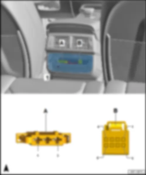
AUDI Q7 2017 Fitting location Rear Climatronic operating and display unit E265

   
Fitting location Rear Climatronic operating and display unit -E265- , air conditioning system KH5
Fitting location
In rear centre console.
AUDI Q7 2017 Fitting location Rear Climatronic operating and display unit E265 https://portal-diagnostov.com/license.html
https://portal-diagnostov.com/license.html Automotive Electricians Portal FZCO Automotive Electricians Portal FZCO
Get access to all wiring diagrams of the carDownload PDF file
1 -  Rear Climatronic operating and display unit -E265- , air conditioning system KH5
B -  8-pin connector -T8y- , black

   
Connector assignment Rear Climatronic operating and display unit -E265- , air conditioning system KH5
-T3by- (A) Designation   -T8y- (B) Designation
1 Heated bench seat cushion for rear left seat -Z10- /Heated backrest for rear left seat -Z11- 1 LIN bus, from B698 connection 3 (LIN bus) in main wiring harness
Coupling point on left A-pillar, bottom -TALU-
A227 Connection 2 (LIN bus) in dash panel wiring harness
Operating and display unit for Climatronic air conditioning system -E87-
2 Terminal 30, from fuse carrier 1 -ST1- in fuse holder F -SF- 2 Terminal 15, from B282 positive connection 6 (15a) in main wiring harness
Fuse carrier 4 -ST4- in fuse holder B -SB-
3 Heated bench seat cushion for rear right seat -Z12- /Heated backrest for rear right seat -Z13- 3 Terminal 31, to 371 earth connection 6 in main wiring harness
379 Earth connection 14 in main wiring harness
79 Earth point, on left B-pillar
    4 Earth, to rear chest vent temperature sensor -G537- /rear left seat temperature sensor -G94- /rear right seat temperature sensor -G95-
    5 Rear chest vent temperature sensor -G537-
    6
    7 Rear left seat temperature sensor -G94-
    8 Rear right seat temperature sensor -G95-

Back to overview .
   
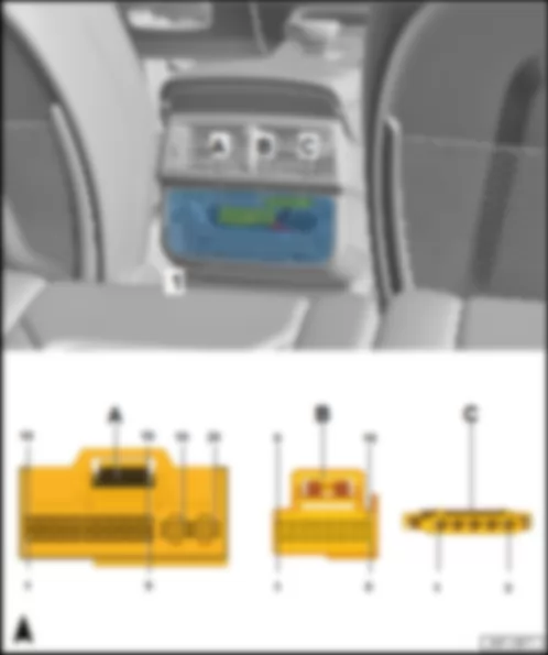
Fitting location Rear Climatronic operating and display unit -E265- , air conditioning system 9AH
Fitting location
In rear centre console.
AUDI Q7 2017 Fitting location Rear Climatronic operating and display unit E265 https://portal-diagnostov.com/license.html
https://portal-diagnostov.com/license.html Automotive Electricians Portal FZCO Automotive Electricians Portal FZCO
Get access to all wiring diagrams of the carDownload PDF file
1 -  Rear Climatronic operating and display unit -E265- , air conditioning system 9AH
B -  16-pin connector -T16l- , black
Connector assignment Rear Climatronic operating and display unit -E265- , air conditioning system 9AH
-T20e- (A) Designation -T16l- (B) Designation   -T5i- (C) Designation
1     1 Rear right temperature flap control motor -V314-   1 Heated bench seat cushion for rear left seat -Z10-
2 Drive high CAN bus from B384 connection 2 (drive high CAN bus) in main wiring harness
Data bus diagnostic interface -J533-
  2 Terminal 30, to L9 connection 1 in air conditioning system wiring harness
Left B-pillar and footwell shut-off flap control motor -V212-
Rear left temperature flap control motor -V313-
Rear left chest vent control motor -V315-
Rear air recirculation flap control motor -V421-
L31 Connection (5 volt) in air conditioning unit wiring harness
Right B-pillar and footwell shut-off flap control motor -V211-
Rear right temperature flap control motor -V314-
Rear right chest vent control motor -V316-
  2 heated backrest for rear left seat -Z11-
3 Drive low CAN bus, from B391 connection 2 (drive low CAN bus) in main wiring harness
Data bus diagnostic interface -J533-
  3 Earth, to L10 connection 2 in air conditioning system wiring harness
Left B-pillar and footwell shut-off flap control motor -V212-
Rear left temperature flap control motor -V313-
Rear left chest vent control motor -V315-
Rear air recirculation flap control motor -V421-
L2 Connection in air conditioning system wiring harness
Right B-pillar and footwell shut-off flap control motor -V211-
Rear right temperature flap control motor -V314-
Rear right chest vent control motor -V316-
  3 Terminal 30, from fuse carrier 1 -ST1- in fuse holder F -SF-
4 Rear passenger side ioniser -J1108-   4 Rear left chest vent temperature sender -G635- 4 Heated bench seat cushion for rear right seat -Z12-
5     5 Vent temperature sender for rear left footwell -G637- 5 Heated backrest for rear right seat -Z13-
6     6 Vent temperature sender for rear right footwell -G638-    
7 Earth, torear left seat temperature sensor -G94- /rear right seat temperature sensor -G95- /rear left backrest temperature sensor -G808- /rear right backrest temperature sensor -G809- 7        
8     8      
9     9 Rear right chest vent temperature sender -G636-    
10     10 Earth, to L7 connection 3 in air conditioner unit wiring harness
Rear left chest vent temperature sender -G635-
Rear right chest vent temperature sender -G636-
Vent temperature sender for rear left footwell -G637-
Vent temperature sender for rear right footwell -G638-
   
11     11      
12     12      
13     13      
14     14      
15 Rear left seat temperature sensor -G94-   15      
16 Rear left seat backrest temperature sensor -G808- 16        
17 Rear right seat temperature sensor -G95-          
18 Rear right seat backrest temperature sensor -G809-          
19 Terminal 31, to 398 earth connection 33 in main wiring harness
393 Earth connection 28 in main wiring harness
688 Earth point 2 on centre tunnel
         
20 Terminal 30, from fuse carrier 2 -ST2- in fuse holder F -SF-            

Back to overview .
   
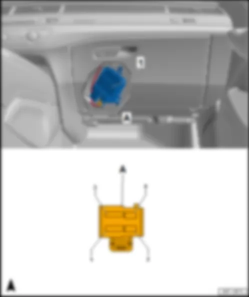
Fitting location, fresh air blower control unit -J126-
Fitting location
Behind the glove component on front heater and air conditioner unit.
AUDI Q7 2017 Fitting location Rear Climatronic operating and display unit E265 https://portal-diagnostov.com/license.html
https://portal-diagnostov.com/license.html Automotive Electricians Portal FZCO Automotive Electricians Portal FZCO
Get access to all wiring diagrams of the carDownload PDF file
1 -  Fresh air blower control unit -J126-
Connector assignment, fresh air blower control unit -J126-
   
-T4f- (A) Designation
1 Terminal 31, to 752 earth point 3 on right A-pillar1)
687 Earth point 1 on centre tunnel2)
2  
3 Terminal 30, from fuse carrier 2 -ST2- in fuse holder B -SB-
4 LIN bus, from A227 connection 2 (LIN bus) in dash panel wiring harness
Operating and display unit for Climatronic air conditioning system -E87-

1) Left-hand drive
2) Right-hand drive
Back to overview .


AUDI Q7 2017

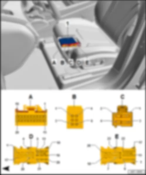
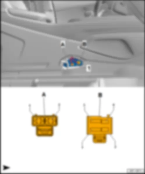
Fitting location, seat and steering column adjustment control unit with memory -J136- /front passenger seat adjustment control unit with memory -J521-
Fitting location
at bottom of seat.
  Note:
The fitting location of the seat and steering column adjustment control unit with memory -J136- is shown. The fitting location of the front passenger seat adjustment with memory control unit -J521- is laterally reversed.
AUDI Q7 2017 https://portal-diagnostov.com/license.html
https://portal-diagnostov.com/license.html Automotive Electricians Portal FZCO Automotive Electricians Portal FZCO
Get access to all wiring diagrams of the carDownload PDF file
1 -  Seat and steering column adjustment control unit with memory -J136- /front passenger seat adjustment control unit with memory -J521-
20-pin connector -T20p- /-T20q- , black
q   20-pin connector -T20p- on seat and steering column adjustment control unit with memory -J136-
q   20-pin connector -T20q- on front passenger seat adjustment control unit with memory -J521-
6-pin connector -T6bk- /-T6bl- , black
q   6-pin connector -T6bk- on seat and steering column adjustment control unit with memory -J136-
q   6-pin connector -T6bl- on front passenger seat adjustment with memory control unit -J521-
4-pin connector -T4fy- /-T4fz- , black
q   4-pin connector -T4fy- on seat and steering column adjustment control unit with memory -J136-
q   4-pin connector -T4fz- on front passenger seat adjustment control unit with memory -J521-
26-pin connector -T26f- /-T26g- , blue
q   26-pin connector -T26f- on seat and steering column adjustment control unit with memory -J136-
q   26-pin connector -T26g- on front passenger seat adjustment control unit with memory -J521-
26-pin connector -T26b- /-T26c- , white
q   26-pin connector -T26b- on seat and steering column adjustment control unit with memory -J136-
q   26-pin connector -T26c- on front passenger seat adjustment control unit with memory -J521-

   
Connector assignment, seat and steering column adjustment control unit with memory -J136-
-T20p- (A) Designation   -T20p- (A) Designation
1 Convenience CAN bus, high, from coupling point for front left seat -TSVL-
B398 Connection 2 (convenience CAN bus, high) in main wiring harness
B402 Connection 6 (convenience CAN bus, high) in main wiring harness
B397 Connection 1 (convenience CAN bus, high) in main wiring harness
Data bus diagnostic interface -J533-
  11 Convenience CAN bus, low, from coupling point for front left seat -TSVL-
B407 Connection 2 (convenience CAN bus, low) in main wiring harness
B411 Connection 6 (convenience CAN bus, low) in main wiring harness
B406 Connection 1 (convenience CAN bus, low) in main wiring harness
Data bus diagnostic interface -J533-
2     12
3 Coding line to contact 20 on connector -T20p- 13
4     14 Driver seat longitudinal adjustment switch -E363- in driver seat adjustment operating unit -E470-
5     15 Driver seat rake adjustment switch -E222- in driver seat adjustment operating unit -E470-
6     16 Driver seat height adjustment switch -E364- in driver seat adjustment operating unit -E470-
7     17 Driver seat backrest adjustment switch -E96- in driver seat adjustment operating unit -E470-
8     18  
9     19 Supply, switch -E96- /-E222- /-E363- /-E364- in the driver seat adjustment operating unit -E470-
10     20 Coding line to contact 3 on connector -T20p-

   
-T6bk- (B) Designation   -T4fy- (C) Designation
1 Lumbar support adjustment valve block on driver side -N209-1) /driver seat lumbar support adjustment pump -V152-2)   1 Terminal 30, from coupling point for left front seat -TSVL-
Driver seat adjustment thermal fuse 1 -S44- on fuse holder B -SB-
2 Lumbar support adjustment valve block on driver side -N209-1) /driver seat lumbar support adjustment pump -V152-2)   2  
3 Lumbar support adjustment valve block on driver side -N209-1) /driver seat lumbar support adjustment pump -V152-2)   3 Terminal 31, to coupling point for left front seat -TSVL-
379 Earth connection 14 in main wiring harness
79 Earth point, on left B-pillar
4 Compressor for multicontour driver seat -V439-1)   4  
5 Compressor for multicontour driver seat -V439-1)    
6        

1) not for normal seat (Q1A)
2) for comfort seat only (Q2J)
   
-T26f- (D) Designation   -T26b- (E) Designation
1 Backrest adjustment sender for driver seat -G219- /driver seat backrest adjustment motor -V45-   1  
2     2
3 Driver seat lumbar support longitudinal adjustment motor -V125-1) /driver seat lumbar support height adjustment motor -V596-2)   3 Longitudinal adjustment sender for driver seat -G218-
4     4 Switch module for driver seat -E663-1)
5     5 Earth, to switch module for driver seat -E663-1) /driver seat massage function button -E670-2) /longitudinal adjustment sender for driver seat -G218-
6     6  
7 Lumbar support height adjustment sender -G374-1)   7 Rake adjustment sender for driver seat -G232- /driver seat rake adjustment motor -V243-
8 Lumbar support longitudinal adjustment sender -G375-1)   8 Driver seat longitudinal adjustment motor -V28-
9     9 Seat depth adjustment sender -G378-1) /driver seat depth adjustment motor -V256-1)
10     10 Height adjustment sender for driver seat -G231- /driver seat height adjustment motor -V245-
11     11  
12     12 Driver seat massage function button -E670-2)
13     13  
14     14 Switch module for driver seat -E663-1)
15     15  
16 Driver seat lumbar support height adjustment motor -V129-1)   16  
17     17 Switch module for driver seat -E663-1)
18 Driver seat lumbar support longitudinal adjustment motor -V125-1) /driver seat lumbar support height adjustment motor -V596-2)   18  
19 Backrest adjustment sender for driver seat -G219- /driver seat backrest adjustment motor -V45-   19  
20     20  
21     21  
22 Earth, to lumbar support height adjustment sender -G374-1) /lumbar support longitudinal adjustment sender -G375-1)   22  
23     23 Rake adjustment sender for driver seat -G232- /driver seat rake adjustment motor -V243-
24     24 Driver seat longitudinal adjustment motor -V28-
25     25 Height adjustment sender for driver seat -G231- /driver seat height adjustment motor -V245-
26 Driver seat lumbar support height adjustment motor -V129-1)   26 Seat depth adjustment sender -G378-1) /driver seat depth adjustment motor -V256-1)

1) not for normal seat (Q1A)
2) for comfort seat only (Q2J)
Back to overview .
   
Connector assignment of control unit for front passenger seat adjustment with memory function -J521-
-T20q- (A) Designation   -T20q- (A) Designation
1 Convenience CAN bus, high, from coupling point for front right seat -TSVR-
B402 Connection 6 (convenience CAN bus, high) in main wiring harness
B397 Connection 1 (convenience CAN bus, high) in main wiring harness
Data bus diagnostic interface -J533-
  11 Convenience CAN bus, low, from coupling point for front right seat -TSVR-
B411 Connection 6 (convenience CAN bus, low) in main wiring harness
B406 Connection 1 (convenience CAN bus, low) in main wiring harness
Data bus diagnostic interface -J533-
2     12
3 Coding line to contact 20 on connector -T20q- 13
4     14 Front passenger seat longitudinal adjustment switch -E64- in front passenger seat adjustment operating unit -E471-
5     15 Front passenger seat rake adjustment button -E334- in front passenger seat adjustment operating unit -E471-
6     16 Front passenger seat height adjustment switch -E365- in front passenger seat adjustment operating unit -E471-
7     17 Front passenger seat backrest adjustment switch -E98- in front passenger seat adjustment operating unit -E471-
8     18  
9     19 Supply, switch -E64- /-E98- /-E334- /-E365- in the front passenger seat adjustment operating unit -E471-
10     20 Coding line to contact 3 on connector -T20q-

   
-T6bl- (B) Designation   -T4fz- (C) Designation
1 Lumbar support adjustment valve block on front passenger side -N210-1) /front passenger side lumbar support adjustment pump -V153-2)   1 Terminal 30, from coupling point for right front seat -TSVR-
Front passenger seat adjustment thermal fuse 1 -S46- on fuse holder F -SF-
2 Lumbar support adjustment valve block on front passenger side -N210-1) /front passenger side lumbar support adjustment pump -V153-2)   2  
3 Lumbar support adjustment valve block on front passenger side -N210-1) /front passenger side lumbar support adjustment pump -V153-2)   3 Terminal 31, to coupling point for right front seat -TSVR-
381 Earth connection 16 in main wiring harness
720 Earth point, on right B-pillar
4 Compressor for multicontour front passenger seat -V440-1)   4  
5 Compressor for multicontour front passenger seat -V440-1)    
6        

1) not for normal seat (Q1A)
2) for comfort seat only (Q2J)
   
-T26g- (D) Designation   -T26c- (E) Designation
1 Backrest adjustment sender for front passenger seat -G279- /front passenger seat backrest adjustment motor -V46-   1  
2     2
3 Front passenger seat lumbar support longitudinal adjustment motor -V126-1) /front passenger seat lumbar support height adjustment motor -V597-2)   3 Longitudinal adjustment sender for front passenger seat -G278-
4     4 Switch module for front passenger seat -E664-1)
5     5 Earth, to switch module for front passenger seat -E664-1) /front passenger seat massage function button -E671-2) /longitudinal adjustment sender for front passenger seat -G278-
6     6  
7 Front passenger lumbar support height adjustment sender -G721-1)   7 Rake adjustment sender for front passenger seat -G359- /front passenger seat rake adjustment motor -V244-
8 Front passenger lumbar support longitudinal adjustment sender -G722-1)   8 Front passenger seat longitudinal adjustment motor -V31-
9     9 Front passenger seat depth adjustment sender -G724-1) /front passenger seat depth adjustment motor -V257-1)
10     10 Sender for height adjustment of front passenger seat -G607- /front passenger seat height adjustment motor -V246-
11     11  
12     12 Front passenger seat massage function button -E671-2)
13     13  
14     14 Switch module for front passenger seat -E664-1)
15     15  
16 Front passenger seat lumbar support height adjustment motor -V130-1)   16  
17     17 Switch module for front passenger seat -E664-1)
18 Front passenger seat lumbar support longitudinal adjustment motor -V126-1) /front passenger seat lumbar support height adjustment motor -V597-2)   18  
19 Backrest adjustment sender for front passenger seat -G279- /front passenger seat backrest adjustment motor -V46-   19  
20     20  
21     21  
22 Earth, to front passenger lumbar support height adjustment sender -G721-1) /front passenger lumbar support longitudinal adjustment sender -G722-1)   22  
23     23 Rake adjustment sender for front passenger seat -G359- /front passenger seat rake adjustment motor -V244-
24     24 Front passenger seat longitudinal adjustment motor -V31-
25     25 Sender for height adjustment of front passenger seat -G607- /front passenger seat height adjustment motor -V246-
26 Front passenger seat lumbar support height adjustment motor -V130-1)   26 Front passenger seat depth adjustment sender -G724-1) /front passenger seat depth adjustment motor -V257-1)

1) not for normal seat (Q1A)
2) for comfort seat only (Q2J)
Back to overview .


AUDI Q7 2017 Fitting location, airbag control unit J234

Fitting location, airbag control unit -J234-
Fitting location
Under centre console at front on centre tunnel
AUDI Q7 2017 Fitting location, airbag control unit J234 https://portal-diagnostov.com/license.html
https://portal-diagnostov.com/license.html Automotive Electricians Portal FZCO Automotive Electricians Portal FZCO
Get access to all wiring diagrams of the carDownload PDF file
1 -  Airbag control unit -J234-
B -  96-pin connector -T96a- , yellow

Back to overview .


AUDI Q7 2017 Fitting location, sliding sunroof adjustment control unit J245

Fitting location, sliding sunroof adjustment control unit -J245-
Fitting location
On front and rear of sliding sunroof frame.
AUDI Q7 2017 Fitting location, sliding sunroof adjustment control unit J245 https://portal-diagnostov.com/license.html
https://portal-diagnostov.com/license.html Automotive Electricians Portal FZCO Automotive Electricians Portal FZCO
Get access to all wiring diagrams of the carDownload PDF file
1 -  Sunroof roller blind motor -V260-
q   with sunroof roller blind motor Hall sensor -G404- and sunroof roller blind motor Hall sensor 2 -G917-
B -  16-pin connector -T16g- , brown
D -  5-pin connector -T5k- , black
Connector assignment, sliding sunroof adjustment control unit -J245-
-T16g- (B) Designation -T4bi- (C) Designation   -T5k- (D) Designation
1 Sliding sunroof motor -V1-   1 Sunroof roller blind motor -V260-   1 Terminal 31, to 689 earth point, at front, central in roof
2 Sliding sunroof motor -V1-   2 Sunroof roller blind motor -V260-   2
3 Sliding sunroof motor -V1- /sunroof roller blind motor -V260-   3 Sliding sunroof motor -V1-   3 Convenience CAN bus, high, to B398 connection 2 (convenience CAN bus, high) in main wiring harness
4 Sliding sunroof adjustment regulator -E139-   4 Sliding sunroof motor -V1- 4 Convenience CAN bus, low, to B407 connection 2 (convenience CAN bus, low) in main wiring harness
5 Sliding sunroof adjustment regulator -E139-       5 Terminal 30, from fuse carrier 3 -ST3- in fuse holder B -SB-
6 Sliding sunroof adjustment regulator -E139-          
7            
8            
9 Sunroof roller blind motor -V260-        
10 Sunroof roller blind motor -V260-        
11 Sliding sunroof motor -V1- /sunroof roller blind motor -V260-        
12 Sliding sunroof adjustment regulator -E139-          
13            
14            
15            
16 Sliding sunroof adjustment regulator -E139-          

Back to overview .


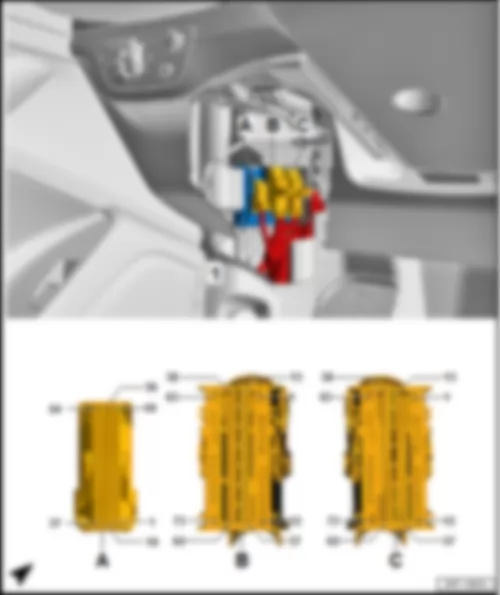
AUDI Q7 2017 Fitting location, control unit in dash panel insert J285

Fitting location, control unit in dash panel insert -J285-
Fitting location
In driver side dash panel.
AUDI Q7 2017 Fitting location, control unit in dash panel insert J285 https://portal-diagnostov.com/license.html
https://portal-diagnostov.com/license.html Automotive Electricians Portal FZCO Automotive Electricians Portal FZCO
Get access to all wiring diagrams of the carDownload PDF file
1 -  Control unit in dash panel insert -J285-
B -  2-pin connector -T2r- , black
q   MOST bus
Connector assignment, control unit in dash panel insert -J285-
-T32a- (C) Designation -T32a- (C) Designation   -T32a- (C) Designation
1 Ring circuit break diagnostic   12     23  
2     13   24  
3 Infotainment low CAN bus, from A179 connection (infotainment low CAN bus) in dash panel wiring harness
Coupling point on left A-pillar, bottom -TALU-
Data bus diagnostic interface -J533-
  14   25  
4 Infotainment high CAN bus, from A178 connection (infotainment high CAN bus) in dash panel wiring harness
Coupling point on left A-pillar, bottom -TALU-
Data bus diagnostic interface -J533-
  15   26  
5     16   27  
6     17   28  
7     18     29  
8 Dash panel insert operating buttons -E493-   19 FlexRay bus, to coupling point at bottom on left A-pillar -TALU-
Control unit for night vision system -J853-
  30 Terminal 31, to 44 earth point at bottom of left A-pillar1)
752 Earth point 3 on right A-pillar2)
9     20 FlexRay bus, to coupling point at bottom on left A-pillar -TALU-
Control unit for night vision system -J853-
  31  
10     21     32 Terminal 30, from fuse holder C -SC-
11     22      

1) Left-hand drive
2) Right-hand drive
Back to overview .


AUDI Q7 2017 Fitting location, battery monitor control unit J367

Fitting location, battery monitor control unit -J367-
Fitting location
In front right of footwell at negative terminal of battery -A- .
AUDI Q7 2017 Fitting location, battery monitor control unit J367 https://portal-diagnostov.com/license.html
https://portal-diagnostov.com/license.html Automotive Electricians Portal FZCO Automotive Electricians Portal FZCO
Get access to all wiring diagrams of the carDownload PDF file
1 -  Battery monitor control unit -J367-
Connector assignment, battery monitor control unit -J367-
   
-T2ct- (A) Designation
1 LIN bus, to B699 connection 4 (LIN bus) in main wiring harness
Data bus diagnostic interface -J533-
2 Terminal 30, from B299 positive connection 3 (30) in main wiring harness
Connection B1, main fuse carrier on the battery -A-

Back to overview .


AUDI Q7 2017 Fitting location, driver door control unit J386

Fitting location, driver door control unit -J386-
Fitting location
In driver door.
AUDI Q7 2017 Fitting location, driver door control unit J386 https://portal-diagnostov.com/license.html
https://portal-diagnostov.com/license.html Automotive Electricians Portal FZCO Automotive Electricians Portal FZCO
Get access to all wiring diagrams of the carDownload PDF file
1 -  Driver door control unit -J386-
B -  16-pin connector -T16e- , black
D -  6-pin connector -T6aq- , black

   
Connector assignment, driver door control unit -J386-
-T32c- (A) Designation   -T16e- (B) Designation
1 Central locking SAFELOCK function warning lamp -K133-   1  
2     2 Driver side automatic anti-dazzle exterior mirror -Y20-
3 Light for driver side interior door handle illumination -L219-   3 Driver side turn signal repeater bulb -L131- /heated exterior mirror on driver side -Z4-
4 Terminal 58s, to R52 connection (58s) in driver door wiring harness
Mirror adjustment switch -E43- /mirror adjustment changeover switch -E48-
Rear lid remote release button -E233-
Driver side interior locking button for central locking system -E308-
Driver side operating unit for memory settings -E464-
Operating unit for window regulator in driver door -E512-
Button for deactivating interior monitoring and vehicle inclination sensor -E616-
  4 Earth, to 107 earth connection in exterior mirror wiring harness
Potentiometer for horizontal adjustment of driver side mirror -G514- /potentiometer for vertical adjustment of driver side mirror -G515-
Lane change assist warning lamp in driver side exterior mirror -K233-
5 Earth, to 267 earth connection 2 in driver door wiring harness
Mirror adjustment switch -E43- /mirror adjustment changeover switch -E48-
Driver side interior locking button for central locking system -E308-
Driver side operating unit for memory settings -E464-
Operating unit for window regulator in driver door -E512-
Button for deactivating interior monitoring and vehicle inclination sensor -E616-
Central locking SAFELOCK function warning lamp -K133-
Light for driver side interior door handle illumination -L219-
Light for driver door ambient lighting -W86-
Light 2 for driver door ambient lighting -W97-
Driver door exit warning light -W111-
404 earth connection 4 in driver door wiring harness
Rear lid remote release button -E233-
Light for driver door loudspeaker trim -L223-
Driver side door warning lamp -W30-
Driver side entry light -W92-
  5 Driver side mirror adjustment motor -V17- /driver side mirror adjustment motor -V149-
6 Driver door exit warning light -W111-   6 Driver side automatic anti-dazzle exterior mirror -Y20-
7     7 Driver side mirror adjustment motor -V17-
8 to R97 connection 4 in driver door wiring harness
Light for driver door loudspeaker trim -L223-
Light for driver door ambient lighting -W86-
Light 2 for driver door ambient lighting -W97-
  8 Driver side mirror adjustment motor -V149-
9     9 Driver side fold-in mirror motor -V121-
10 Button for deactivating interior monitoring and vehicle inclination sensor -E616-   10 Driver side fold-in mirror motor -V121-
11 Operating unit for window regulator in driver door -E512-
Warning lamp for activated right childproof lock -K272-
  11 Driver side turn signal repeater bulb -L131-
12 Operating unit for window regulator in driver door -E512-
Warning lamp for activated left childproof lock -K271-
  12 Lane change assist warning lamp in driver side exterior mirror -K233-
13 Driver side interior locking button for central locking system -E308-   13 Potentiometer for horizontal adjustment of driver side mirror -G514-
14     14 Potentiometer for horizontal adjustment of driver side mirror -G514- /potentiometer for vertical adjustment of driver side mirror -G515-
15 Driver side operating unit for memory settings -E464-
Driver seat memory function button -E283-
  15 Heated exterior mirror on driver side -Z4-
16 to R56 connection (entry light) in driver door wiring harness
Driver side door warning lamp -W30-
Driver side entry light -W92-
  16 Potentiometer for vertical adjustment of driver side mirror -G515-
17 Driver side operating unit for memory settings -E464-      
18      
19 Driver side operating unit for memory settings -E464-
Seat memory position button 1 in driver door -E218- /seat memory position button 2 in driver door -E219-
     
20 Button for deactivating interior monitoring and vehicle inclination sensor -E616-    
21        
22        
23 Rear lid remote release button -E233-    
24 Mirror adjustment switch -E43-      
25 Mirror adjustment changeover switch -E48-      
26        
27 Operating unit for window regulator in driver door -E512-    
28 Driver side interior locking button for central locking system -E308-    
29 Operating unit for window regulator in driver door -E512-
Rear passenger side window regulator button, in driver door -E714-
     
30 Operating unit for window regulator in driver door -E512-
Rear driver side window regulator button, in driver door -E712-
     
31 Operating unit for window regulator in driver door -E512-
Front passenger side window regulator button, in driver door -E715-
     
32 Operating unit for window regulator in driver door -E512-
Front driver side window regulator button -E710-


-T20h- (C) Designation   -T6aq- (D) Designation
1 Driver side central locking lock unit -F220-   1  
2 Driver side central locking lock unit -F220-   2  
3 Front left door exterior handle illumination bulb -L162-   3 Driver side window regulator motor -V147-
4 Driver side central locking lock unit -F220-   4  
5 Driver side central locking lock unit -F220-   5 Driver door power latching motor -V302-
6 Driver side central locking lock unit -F220-   6 Driver side window regulator motor -V147-
7 Driver door power latching motor -V302-    
8      
9      
10 LIN bus, to coupling point on front left door -TTVL-
Coupling point on rear left door -TTHL-
Rear driver side door control unit -J926-
   
11 Driver side central locking lock unit -F220-
Driver door central locking SAFELOCK function motor -V161- /central locking motor on driver side -V503-
     
12 Driver side central locking lock unit -F220-
Driver door central locking SAFELOCK function motor -V161-
     
13 Driver side central locking lock unit -F220-
Driver side central locking motor -V503-
   
14 Convenience CAN bus, low, from coupling point on front left door -TTVL-
B407 Connection 2 (convenience CAN bus, low) in main wiring harness
B411 Connection 6 (convenience CAN bus, low) in main wiring harness
B406 Connection 1 (convenience CAN bus, low) in main wiring harness
Data bus diagnostic interface -J533-
     
15 Convenience CAN bus, high, from coupling point on front left door -TTVL-
B398 Connection 2 (convenience CAN bus, high) in main wiring harness
B402 Connection 6 (convenience CAN bus, high) in main wiring harness
B397 Connection 1 (convenience CAN bus, high) in main wiring harness
Data bus diagnostic interface -J533-
   
16 Light for driver side sill panel moulding ambient lighting -W102-      
17      
18      
19 Terminal 30, from R94 connection 1 in driver door wiring harness
Coupling point on front left door -TTVL-
Fuse carrier 3 -ST3- in fuse holder B -SB-
     
20 Terminal 31, to 205 earth connection in driver side door wiring harness
Coupling point on front left door -TTVL-
369 Earth connection 4 in main wiring harness
645 Earth point 1, on bulkhead
 

Back to overview .


AUDI Q7 2017 Fitting location, front passenger door control unit J387

Fitting location, front passenger door control unit -J387-
Fitting location
In front passenger door.
AUDI Q7 2017 Fitting location, front passenger door control unit J387 https://portal-diagnostov.com/license.html
https://portal-diagnostov.com/license.html Automotive Electricians Portal FZCO Automotive Electricians Portal FZCO
Get access to all wiring diagrams of the carDownload PDF file
1 -  Front passenger door control unit -J387-
B -  16-pin connector -T16f- , black
D -  6-pin connector -T6ar- , black

   
Connector assignment, front passenger door control unit -J387-
-T32d- (A) Designation   -T16f- (B) Designation
1     1
2     2 Front passenger side automatic anti-dazzle exterior mirror -Y21-
3 Light for front passenger side interior door handle illumination -L220-   3 Front passenger side turn signal repeater bulb -L132- /heated exterior mirror on front passenger side -Z5-
4 Terminal 58s, to R53 connection (58s) in front passenger door wiring harness
Front passenger side interior locking button for central locking system -E309-
Front passenger side operating unit for memory settings -E465-
Front passenger side window regulator button -E716-
  4 Earth, to 107 earth connection in exterior mirror wiring harness
Potentiometer for horizontal adjustment of front passenger side mirror -G516- /Potentiometer for vertical adjustment of front passenger side mirror -G517-
Lane change assist warning lamp in front passenger side exterior mirror -K234-
5 Earth, to 268 earth connection 2 in front passenger door wiring harness
Front passenger side interior locking button for central locking system -E309-
Front passenger side operating unit for memory settings -E465-
Front passenger side window regulator button -E716-
Light for front passenger side interior door handle illumination -L220-
Light for passenger door ambient lighting -W87-
Light 2 for front passenger door ambient lighting -W98-
Front passenger door exit warning light -W112-
405 earth connection 4 in front passenger door wiring harness
Light for passenger side door loudspeaker trim -L224-
Front passenger side door warning light -W36-
Front passenger side entry light -W93-
  5 Front passenger side mirror adjustment motor -V25- /front passenger side mirror adjustment motor -V150-
6 Front passenger door exit warning light -W112-   6 Front passenger side automatic anti-dazzle exterior mirror -Y21-
7     7 Front passenger side mirror adjustment motor -V25-
8 to R99 connection 2 in front passenger door wiring harness
Light for passenger side door loudspeaker trim -L224-
Light for passenger door ambient lighting -W87-
Light 2 for front passenger door ambient lighting -W98-
  8 Front passenger side mirror adjustment motor -V150-
9     9 Front passenger side fold-in mirror motor -V122-
10     10 Front passenger side fold-in mirror motor -V122-
11     11 Front passenger side turn signal repeater bulb -L132-
12     12 Lane change assist warning lamp in front passenger side exterior mirror -K234-
13 Front passenger side interior locking button for central locking system -E309-   13 Potentiometer for horizontal adjustment of front passenger side mirror -G516-
14     14 Potentiometer for horizontal adjustment of front passenger side mirror -G516- /Potentiometer for vertical adjustment of front passenger side mirror -G517-
15 Front passenger side operating unit for memory settings -E465-
Front passenger seat memory function button -E340-
  15 Heated exterior mirror on front passenger side -Z5-
16 to R100 connection 3 in front passenger door wiring harness
Front passenger side door warning light -W36-
Front passenger side entry light -W93-
  16 Front passenger side potentiometer for vertical mirror adjustment -G517-
17 Front passenger side operating unit for memory settings -E465-    
18      
19 Front passenger side operating unit for memory settings -E465-
Seat memory position button 1 in front passenger door -E513- /seat memory position button 2 in front passenger door -E514-
   
20      
21        
22        
23        
24        
25        
26        
27        
28 Front passenger side interior locking button for central locking system -E309-    
29        
30        
31        
32 Front passenger side window regulator button -E716-    

   
-T20i- (C) Designation   -T6ar- (D) Designation
1     1
2 Front passenger side central locking lock unit -F221-   2  
3 Front right door exterior handle illumination bulb -L163-   3 Front passenger side window regulator motor -V148-
4 Front passenger side central locking lock unit -F221-   4  
5 Front passenger side central locking lock unit -F221-   5 Front passenger door power latching motor -V303-
6 Front passenger side central locking lock unit -F221-   6 Front passenger side window regulator motor -V148-
7 Front passenger door power latching motor -V303-    
8      
9      
10 LIN bus, to coupling point on front right door -TTVR-
Coupling point on rear right door -TTHR-
Rear passenger side door control unit -J927-
   
11 Front passenger side central locking lock unit -F221-
Front passenger door central locking SAFELOCK function motor -V162- /central locking motor on front passenger side -V504-
     
12 Front passenger side central locking lock unit -F221-
Front passenger door central locking SAFELOCK function motor -V162-
     
13 Front passenger side central locking lock unit -F221-
Front passenger side central locking motor -V504-
   
14 Convenience CAN bus, low, from coupling point on front right door -TTVR-
B411 Connection 6 (convenience CAN bus, low) in main wiring harness
B406 Connection 1 (convenience CAN bus, low) in main wiring harness
Data bus diagnostic interface -J533-
     
15 Convenience CAN bus, high, from coupling point on front right door -TTVR-
B402 Connection 6 (convenience CAN bus, high) in main wiring harness
B397 Connection 1 (convenience CAN bus, high) in main wiring harness
Data bus diagnostic interface -J533-
   
16 Light for sill panel moulding ambient lighting, front passenger side -W103-      
17      
18      
19 Terminal 30, from R16 positive connection 1 (30) in front passenger door wiring harness
Coupling point on front right door -TTVR-
Fuse carrier 5 -ST5- in fuse holder B -SB-
     
20 Terminal 31, to 206 earth connection in front passenger door wiring harness
Coupling point on front right door -TTVR-
394 Earth connection 29 in main wiring harness
638 Earth point on right A-pillar
 

Back to overview .


AUDI Q7 2017 Fitting location Rear fresh air blower control unit J391

Fitting location Rear fresh air blower control unit -J391-
Fitting location
On heater/air conditioner, in the centre console
AUDI Q7 2017 Fitting location Rear fresh air blower control unit J391 https://portal-diagnostov.com/license.html
https://portal-diagnostov.com/license.html Automotive Electricians Portal FZCO Automotive Electricians Portal FZCO
Get access to all wiring diagrams of the carDownload PDF file
1 -  Rear fresh air blower control unit -J391-
Connector assignment of rear fresh air blower control unit -J391-
   
-T4dz- (A) Designation
1 Terminal 31, to coupling point in interior, centre -TIM-
398 Earth connection 33 in main wiring harness
393 Earth connection 28 in main wiring harness
688 Earth point 2 on centre tunnel
2  
3 Terminal 30, from coupling point in interior, centre -TIM-
Fuse carrier 2 -ST2- in fuse holder F -SF-
4 LIN bus, from coupling point in interior, centre -TIM-
B698 Connection 3 (LIN bus) in main wiring harness
Coupling point on left A-pillar, bottom -TALU-
A227 Connection 2 (LIN bus) in dash panel wiring harness
Operating and display unit for Climatronic air conditioning system -E87-

Back to overview .


AUDI Q7 2017 Fitting location, multifunction steering wheel control unit J453

Fitting location, multifunction steering wheel control unit -J453-
Fitting location
On the right of the steering wheel in the multifunction buttons on right in steering wheel -E441- .
AUDI Q7 2017 Fitting location, multifunction steering wheel control unit J453 https://portal-diagnostov.com/license.html
https://portal-diagnostov.com/license.html Automotive Electricians Portal FZCO Automotive Electricians Portal FZCO
Get access to all wiring diagrams of the carDownload PDF file
1 -  Multifunction steering wheel control unit -J453-
q   in the multifunction buttons on right in steering wheel -E441- .
A -  3-pin connector -T3- , black
q   to Tiptronic switch (shift up) -E479-
B -  11-pin connector -T11- , black
q   to multifunction buttons on the left in the steering wheel -E440-
Connector assignment, multifunction steering wheel control unit -J453-
   
-T4bd- (C) Designation
1 LIN bus, from spring -F350-
2 Terminal 30, from spring -F350-
3 Terminal 31, from spring -F350-
4 Horn plate -H-

Back to overview .


AUDI Q7 2017 Fitting location, heated windscreen control unit J505

Fitting location, heated windscreen control unit -J505-
Fitting location
on right A-pillar, centre.
AUDI Q7 2017 Fitting location, heated windscreen control unit J505 https://portal-diagnostov.com/license.html
https://portal-diagnostov.com/license.html Automotive Electricians Portal FZCO Automotive Electricians Portal FZCO
Get access to all wiring diagrams of the carDownload PDF file
1 -  Heated windscreen control unit -J505-
Connector assignment of heated windscreen control unit -J505-
   
-T4i- (A) Designation
1 Heated windscreen -Z2-
2 Heated windscreen -Z2-
3 Terminal 30, from bottom coupling point on right A-pillar -TARU-
B299 Positive connection 3 (30), in main wiring harness
Connection B1, main fuse carrier on the battery -A-
4 LIN bus, from bottom coupling point on right A-pillar -TARU-
Convenience system central control unit -J393-

Back to overview .


AUDI Q7 2017 Fitting location, onboard supply control unit J519

Fitting location, onboard supply control unit -J519-
Fitting location
on left A-pillar.
AUDI Q7 2017 Fitting location, onboard supply control unit J519 https://portal-diagnostov.com/license.html
https://portal-diagnostov.com/license.html Automotive Electricians Portal FZCO Automotive Electricians Portal FZCO
Get access to all wiring diagrams of the carDownload PDF file
1 -  Onboard supply control unit -J519-
B -  73-pin connector -T73a- , black
Connector assignment, onboard supply control unit -J519-
-T54b- (A) Designation -T73a- (B) Designation   -T73b- (C) Designation
1 Entry and start authorisation button -E408-   1 12 V sockets -U5- /-U18- /-U19- /-U20-   1 Terminal 30, from fuse carrier 3 -ST3- in fuse holder B -SB-
2 Front right footwell illumination bulb -L152-   2 Terminal 30, from fuse carrier 5 -ST5- in fuse holder B -SB-   2 Headlight washer system pump -V11-
3 Front left footwell illumination bulb -L151-   3   3 Washer pump -V5- /rear window wiper motor -V12-
4     4   4 Washer pump -V5- /rear window wiper motor -V12-
5     5   5 Treble horn -H2- /bass horn -H7-
6     6   6  
7     7 Terminal 15, from B450 connection 1 (PDC) in main wiring harness
Fuse carrier 4 -ST4- in fuse holder B -SB-
  7  
8     8 Air conditioning system magnetic clutch -N25-   8  
9     9     9 Heating resistors for nozzles -Z20- /-Z21- /-Z114-
10     10     10 Front right heated seat backrest -Z117-
11 Earth, to centre dash panel switch module -EX22-   11 Rear left footwell illumination bulb -L106- /rear right footwell illumination bulb -L107-   11 Heated front passenger seat -Z8- /front passenger seat lateral support heater -Z33- /heated seat extension for front passenger seat -Z38-
12     12 Terminal 30, from fuse carrier 5 -ST5- in fuse holder B -SB-   12 Terminal 30, from fuse carrier 5 -ST5- in fuse holder B -SB-
13     13   13  
14     14     14  
15     15     15  
16     16 Air conditioner compressor regulating valve -N280-   16 Earth, to 348 earth connection (parking aid), in front bumper wiring harness
Front parking aid sender -G252- /-G253- /-G254- /-G255-
Front park assist steering sender -G568- /-G569-
17     17 Auto-hold warning lamp -K237-   17 Earth, to 352 earth connection (parking aid), in rear bumper wiring harness
Rear parking aid sender -G203- /-G204- /-G205- /-G206-
Rear park assist steering sender -G716- /-G717-
18 LIN bus, to control unit for electrically adjustable steering column -J866-   18   18 Front left parking aid sender -G255-
19 Front parking aid warning buzzer -H22-   19 Terminal 15, to B281 positive connection 5 (15a) in main wiring harness   19 Supply, to X65 connection (parking aid), in front bumper wiring harness
Front parking aid sender -G252- /-G253- /-G254- /-G255-
Front park assist steering sender -G568- /-G569-
20 Front parking aid warning buzzer -H22-   20 Front left brake pad wear sender -G34-   20 Supply, to X68 connection (parking aid), in rear bumper wiring harness
Rear parking aid sender -G203- /-G204- /-G205- /-G206-
Rear park assist steering sender -G716- /-G717-
21     21 Brake fluid level warning contact -F34-   21 Front right parking aid sender -G252-
22     22 LIN bus, to wiper motor control unit -J400-   22 Front centre right parking aid sender -G253-
23     23 LIN bis. to rain and light sensor -G397- 23 Front left seat temperature sender -G344-
24     24 LIN bus, to B549 connection 2 (LIN bus) in main wiring harness
Garage door operating unit -E284-
Roof electronics control unit -J528-
Garage door operation control unit -J530-
Automatic anti-dazzle interior mirror -Y7-
  24  
25     25 LIN bus, to seat fans -V388- /-V389- /-V390- /-V391-   25 Front left backrest temperature sensor -G806-
26     26     26 Front right seat temperature sender -G345-
27     27 LIN bus, to B711 connection 6 (LIN bus) in main wiring harness
Light for front left door contour lighting -L251-
Light for front right door contour lighting -L252-
Light for rear left door contour lighting -L253-
Light for rear right door contour lighting -L254-
Light conductor for front centre console ambient lighting -W74-
  27 Front right backrest temperature sensor -G807-
28     28 LIN bus (ambient lighting), to dash panel contour illumination light 3 -L245-   28  
29     29     29  
30 LIN bus, to light switch -E1-   30 Bonnet contact switch 2 -F329-   30  
31     31 Bonnet contact switch -F266-   31 Auto-hold button -E540-
32     32 Terminal 58s, to B732 connection 2 (58s) in main wiring harness
B731 connection 1 (58s) in main wiring harness
  32  
33     33     33  
34     34 Terminal 58s, to roof electronics control unit -J528-   34  
35     35 Rear parking aid warning buzzer -H15-   35  
36     36 Supply, to A138 connection 2 in dash panel wiring harness
Light 1 for dash panel contour lighting -L243-
Light 2 for dash panel contour lighting -L244-
  36  
37 Terminal 58s, to A3 positive connection (58) in dash panel wiring harness
A175 connection (58s), in dash panel wiring harness
B732 connection 2 (58s) in main wiring harness 1)
  37   37  
38     38 Air conditioner compressor regulating valve -N280-   38  
39 Glove compartment light -W6-   39     39
40     40 Earth, to 410 earth connection 1 (sender earth) in main wiring harness   40 Convenience CAN bus, high, from B398 connection 2 (convenience CAN bus, high) in main wiring harness
B402 Connection 6 (convenience CAN bus, high) in main wiring harness
B397 Connection 1 (convenience CAN bus, high) in main wiring harness
Data bus diagnostic interface -J533-
41     41     41 Convenience CAN bus, low, to B407 connection 2 (convenience CAN bus, low) in main wiring harness
B411 Connection 6 (convenience CAN bus, low) in main wiring harness
B406 Connection 1 (convenience CAN bus, low) in main wiring harness
Data bus diagnostic interface -J533-
42     42 Extended low CAN bus, to B109 connection 1 (extended low CAN bus) in main wiring harness
Front left headlight -MX1-
Front camera for driver assist systems -R242-
  42 Extended high CAN bus, to front right headlight -MX2-
43     43 Extended high CAN bus, to B108 connection 1 (extended high CAN bus) in main wiring harness
Front left headlight -MX1-
Front camera for driver assist systems -R242-
  43 Extended low CAN bus, to front right headlight -MX2-
44     44 Windscreen washer fluid level sender -G33-   44  
45     45 Coolant shortage indicator sender -G32-   45  
46     46 Ambient temperature sensor -G17-   46 Seat heating control unit -J882-
47     47     47  
48     48     48 Front centre left parking aid sender -G254-
49     49     49  
50 LIN bus, to light switch -E1-   50     50 Front right sender for park assist steering on right side of vehicle -G569-
51 Lin bus, to centre dash panel switch module -EX22-   51   51 Front left sender for park assist steering on left side of vehicle -G568-
52     52     52 Rear right parking aid sender -G206-
53 LIN bus, to dash panel contour illumination light 1 -L243-   53 Rear parking aid warning buzzer -H15-   53 Rear left parking aid sender -G203-
54     54     54  
      55     55 Rear centre right parking aid sender -G205-
      56     56 Rear centre left parking aid sender -G204-
      57     57 Rear right park assist steering sender -G717-
      58     58 Rear left park assist steering sender -G716-
      59 Ambient light power supply, to B470 connection 6 in main wiring harness   59  
      60     60  
      61     61  
      62     62  
      63 Terminal 31, to 369 earth connection 4 in main wiring harness
645 Earth point 1, on bulkhead
  63 Terminal 31, to 369 earth connection 4 in main wiring harness
645 Earth point 1, on bulkhead
      64 Front left headlight -MX1-   64 Front right headlight -MX2-
      65 Front left headlight -MX1-   65 Front right headlight -MX2-
      66 Terminal 30, from fuse carrier 3 -ST3- in fuse holder B -SB-   66 Terminal 30, from fuse carrier 3 -ST3- in fuse holder B -SB-
      67 Front right headlight -MX2-   67 Front left headlight -MX1-
      68     68  
      69     69  
      70     70  
      71     71 Heated front passenger seat -Z6- /driver seat cushion lateral support heater -Z31- /heated seat extension for driver seat -Z37-
      72 Illuminated vanity mirror -W14- /-W20-   72 Front left heated seat backrest -Z116-
      73 Terminal 30, from fuse carrier 3 -ST3- in fuse holder B -SB-   73 Terminal 30, from fuse carrier 3 -ST3- in fuse holder B -SB-

1) models with air conditioning system KH5 only
Back to overview .


AUDI Q7 2017 Fitting location, steering column electronics control unit J527

Fitting location, steering column electronics control unit -J527-
Fitting location
On steering column.
AUDI Q7 2017 Fitting location, steering column electronics control unit J527 https://portal-diagnostov.com/license.html
https://portal-diagnostov.com/license.html Automotive Electricians Portal FZCO Automotive Electricians Portal FZCO
Get access to all wiring diagrams of the carDownload PDF file
1 -  Steering column electronics control unit -J527-
Connector assignment, steering column electronics control unit -J527-
-T17e- (A) Designation   -T17e- (A) Designation
1 Terminal 30, from fuse holder C -SC- 10
2 LIN bus, to coupling point at bottom on left A-pillar -TALU-
Data bus diagnostic interface -J533-
  11 Airbag control unit -J234-
3 FlexRay bus, from coupling point at bottom on left A-pillar -TALU-
Data bus diagnostic interface -J533-1) or
running gear control unit -J775-2) or
front camera for driver assist systems -R242-3)
  12 Airbag control unit -J234-
4 FlexRay bus, from coupling point at bottom on left A-pillar -TALU-
Data bus diagnostic interface -J533-1) or
running gear control unit -J775-2) or
front camera for driver assist systems -R242-3)
  13 Airbag control unit -J234-
5     14 Airbag control unit -J234-
6     15 Terminal 30, from fuse holder C -SC-
7 Engine control unit -J623-   16  
8     17 Terminal 31, to 44 earth point at bottom of left A-pillar4)
752 Earth point 3 on right A-pillar5)
9      

1) only models without running gear control unit -J775- and without front camera for driver assist systems -R242-
2) only models with running gear control unit -J775- and without front camera for driver assist systems -R242-
3) Only models with front camera for driver assist systems -R242-
4) Left-hand drive
5) Right-hand drive
Back to overview .


AUDI Q7 2017 Fitting location, roof electronics control unit J528

Fitting location, roof electronics control unit -J528-
Fitting location
In front roof module -WX3- .
AUDI Q7 2017 Fitting location, roof electronics control unit J528 https://portal-diagnostov.com/license.html
https://portal-diagnostov.com/license.html Automotive Electricians Portal FZCO Automotive Electricians Portal FZCO
Get access to all wiring diagrams of the carDownload PDF file
1 -  Roof electronics control unit -J528-
B -  4-pin connector -T4fl- , black
q   for front right microphone -R141-
D -  3-pin connector -T3ai- , black
q   for garage door operating unit -E284-
F -  10-pin connector -T10r- , brown
q   for sliding sunroof adjustment regulator -E139-
H -  4-pin connector -T4ed- , black
q   for interior microphone -R74-

Connector assignment of roof electronics control unit -J528-
   
-T6bc- (A) Designation
1  
2 Terminal 58s, from onboard supply control unit -J519-
3 Terminal 30, from fuse carrier 5 -ST5- in fuse holder B -SB-
4  
5 Terminal 31, to 395 earth connection 30 in main wiring harness
689 Earth point at centre front of roof
6 LIN bus, from B549 connection 2 (LIN bus) in main wiring harness
Onboard supply control unit -J519-

Back to overview .


AUDI Q7 2017 Fitting location, data bus diagnostic interface J533

   
Fitting location, data bus diagnostic interface -J533- , models without Audi connect emergency call & service (IW0)
Fitting location
Under front left seat on floor panel.
AUDI Q7 2017 Fitting location, data bus diagnostic interface J533 https://portal-diagnostov.com/license.html
https://portal-diagnostov.com/license.html Automotive Electricians Portal FZCO Automotive Electricians Portal FZCO
Get access to all wiring diagrams of the carDownload PDF file
1 -  Data bus diagnostic interface -J533-
Connector assignment, data bus diagnostic interface -J533-
-T54a- (A) Designation -T54a- (A) Designation   -T54a- (A) Designation
1     19   37  
2     20   38  
3 FlexRay bus, to diagnostic connection -U31-   21 FlexRay bus, to diagnostic connection -U31- 39  
4 FlexRay bus, to diagnostic connection -U31-   22 FlexRay bus, to diagnostic connection -U31- 40  
5 FlexRay bus, to all-wheel drive control unit -J492-1)
Rear wheel steering control unit -J1019-2)
  23 FlexRay bus, to all-wheel drive control unit -J492-1)
Rear wheel steering control unit -J1019-2)
  41 FlexRay bus, from all-wheel drive control unit -J492-
6     24   42 FlexRay bus, from all-wheel drive control unit -J492-
7 FlexRay bus, to control unit 2 for adaptive cruise control -J850-   25 FlexRay bus, to control unit 2 for adaptive cruise control -J850-   43
8 FlexRay bus, to airbag control unit -J234-   26 FlexRay bus, to airbag control unit -J234-   44  
9 FlexRay bus, to automatic gearbox control unit -J217-   27 FlexRay bus, to automatic gearbox control unit -J217-   45 FlexRay bus, to steering column electronics control unit -J527-3) or
front camera for driver assist systems -R242-4) or
running gear control unit -J775-5)
10 FlexRay bus, to engine control unit -J623-   28 FlexRay bus, to engine control unit -J623-   46 FlexRay bus, to steering column electronics control unit -J527-3) or
front camera for driver assist systems -R242-4) or
running gear control unit -J775-5)
11 Drive high CAN bus to B383 connection 1 (drive high CAN bus) in main wiring harness   29 Drive low CAN bus, to B390 connection 1 (drive low CAN bus) in main wiring harness   47  
12 Extended high CAN bus, to B670 connection 3 (extended high CAN bus) in main wiring harness   30 Extended low CAN bus, to B671 connection 3 (extended low CAN bus) in main wiring harness   48 Diagnostic low CAN bus, to diagnostic connection -U31-
13 Infotainment high CAN bus, to A178 connection (infotainment high CAN bus) in dash panel wiring harness   31 Infotainment low CAN bus, to A179 connection (infotainment low CAN bus) in dash panel wiring harness 49 Diagnostic high CAN bus, to diagnostic connection -U31-
14     32     50 Drive low CAN bus, to B391 connection 2 (drive low CAN bus) in main wiring harness
15 Convenience CAN bus, high, to B397 connection 1 (convenience CAN bus, high) in main wiring harness   33 Convenience CAN bus, low, to B406 connection 1 (convenience CAN bus, low) in main wiring harness   51 Drive high CAN bus to B384 connection 2 (drive high CAN bus) in main wiring harness
16 LIN bus, to B699 connection 4 (LIN bus) in main wiring harness
Battery monitor control unit -J367-
Alternator -C-
34 LIN bus, to steering column electronics control unit -J527-   52  
17 Terminal 15, from B450 connection 1 (PDC) in main wiring harness
Fuse carrier 4 -ST4- in fuse holder B -SB-
  35     53
18 Terminal 30, from fuse carrier 5 -ST5- in fuse holder B -SB-   36 Diagnostic connection -U31-   54 Earth, to 79 earth point on left B-pillar

1) Only models with all-wheel drive control unit -J492-
2) Only models without all-wheel drive control unit -J492-
3) only models without running gear control unit -J775- and without front camera for driver assist systems -R242-
4) only models without running gear control unit -J775- and with front camera for driver assist systems -R242-
5) Only models with running gear control unit -J775-
Back to overview .
   
Fitting location, data bus diagnostic interface -J533- , models with Audi connect emergency call & service (IW3)
Fitting location
Under front left seat on floor panel.
AUDI Q7 2017 Fitting location, data bus diagnostic interface J533 https://portal-diagnostov.com/license.html
https://portal-diagnostov.com/license.html Automotive Electricians Portal FZCO Automotive Electricians Portal FZCO
Get access to all wiring diagrams of the carDownload PDF file
1 -  Data bus diagnostic interface -J533-
B -  54-pin connector -T54c- , blue
C -  54-pin connector -T54a- , black

   
Connector assignment, data bus diagnostic interface -J533-
-T54c- (B) Designation -T54c- (B) Designation   -T54c- (B) Designation
1     19   37  
2 Loudspeaker for special signals -R80-   20     38  
3 Loudspeaker for special signals -R80-   21     39  
4     22   40  
5 Control unit 1 for information electronics -J794-   23   41  
6 Control unit 1 for information electronics -J794-   24   42  
7     25     43  
8     26     44  
9 Left front microphone -R140-   27     45  
10 Left front microphone -R140-   28     46  
11 Control unit 1 for information electronics -J794-   29     47  
12 Control unit 1 for information electronics -J794-   30     48  
13 Control unit 1 for information electronics -J794-   31     49  
14 Airbag control unit -J234-   32     50  
15     33     51  
16     34     52  
17     35     53  
18     36     54 Screen earth

   
-T54a- (C) Designation -T54a- (C) Designation   -T54a- (C) Designation
1     19   37  
2     20   38  
3 FlexRay bus, to diagnostic connection -U31-   21 FlexRay bus, to diagnostic connection -U31- 39  
4 FlexRay bus, to diagnostic connection -U31-   22 FlexRay bus, to diagnostic connection -U31- 40  
5 FlexRay bus, to all-wheel drive control unit -J492-1)
Rear wheel steering control unit -J1019-2)
  23 FlexRay bus, to all-wheel drive control unit -J492-1)
Rear wheel steering control unit -J1019-2)
  41 FlexRay bus, from all-wheel drive control unit -J492-
6     24   42 FlexRay bus, from all-wheel drive control unit -J492-
7 FlexRay bus, to control unit 2 for adaptive cruise control -J850-   25 FlexRay bus, to control unit 2 for adaptive cruise control -J850-   43
8 FlexRay bus, to airbag control unit -J234-   26 FlexRay bus, to airbag control unit -J234-   44  
9 FlexRay bus, to automatic gearbox control unit -J217-   27 FlexRay bus, to automatic gearbox control unit -J217-   45 FlexRay bus, to steering column electronics control unit -J527-3) or
front camera for driver assist systems -R242-4) or
running gear control unit -J775-5)
10 FlexRay bus, to engine control unit -J623-   28 FlexRay bus, to engine control unit -J623-   46 FlexRay bus, to steering column electronics control unit -J527-3) or
front camera for driver assist systems -R242-4) or
running gear control unit -J775-5)
11 Drive high CAN bus to B383 connection 1 (drive high CAN bus) in main wiring harness   29 Drive low CAN bus, to B390 connection 1 (drive low CAN bus) in main wiring harness   47  
12 Extended high CAN bus, to B670 connection 3 (extended high CAN bus) in main wiring harness   30 Extended low CAN bus, to B671 connection 3 (extended low CAN bus) in main wiring harness   48 Diagnostic low CAN bus, to diagnostic connection -U31-
13 Infotainment high CAN bus, to A178 connection (infotainment high CAN bus) in dash panel wiring harness   31 Infotainment low CAN bus, to A179 connection (infotainment low CAN bus) in dash panel wiring harness 49 Diagnostic high CAN bus, to diagnostic connection -U31-
14     32     50 Drive low CAN bus, to B391 connection 2 (drive low CAN bus) in main wiring harness
15 Convenience CAN bus, high, to B397 connection 1 (convenience CAN bus, high) in main wiring harness   33 Convenience CAN bus, low, to B406 connection 1 (convenience CAN bus, low) in main wiring harness   51 Drive high CAN bus to B384 connection 2 (drive high CAN bus) in main wiring harness
16 LIN bus, to B699 connection 4 (LIN bus) in main wiring harness
Battery monitor control unit -J367-
Alternator -C-
34 LIN bus, to steering column electronics control unit -J527-   52  
17 Terminal 15, from B450 connection 1 (PDC) in main wiring harness
Fuse carrier 4 -ST4- in fuse holder B -SB-
  35     53
18 Terminal 30, from fuse carrier 5 -ST5- in fuse holder B -SB-   36 Diagnostic connection -U31-   54 Earth, to 79 earth point on left B-pillar

1) Only models with all-wheel drive control unit -J492-
2) Only models without all-wheel drive control unit -J492-
3) only models without running gear control unit -J775- and without front camera for driver assist systems -R242-
4) only models without running gear control unit -J775- and with front camera for driver assist systems -R242-
5) Only models with running gear control unit -J775-
Back to overview .
   
Fitting location, fuel pump control unit -J538-
Fitting location
Under rear seat bench, on fuel tank.
AUDI Q7 2017 Fitting location, data bus diagnostic interface J533 https://portal-diagnostov.com/license.html
https://portal-diagnostov.com/license.html Automotive Electricians Portal FZCO Automotive Electricians Portal FZCO
Get access to all wiring diagrams of the carDownload PDF file
1 -  Fuel pump control unit -J538-
Connector assignment, fuel pump control unit -J538-
   
-T6s- (A) Designation
1 Fuel system pressurisation pump -G6-
2 Fuel system pressurisation pump -G6-
3 Fuel system pressurisation pump -G6-
4 Terminal 31, to 480 earth connection in fuel tank wiring harness
Coupling point for fuel delivery unit -TKFE-
378 Earth connection 13 in main wiring harness
62 Earth point on right C-pillar
5 Terminal 87, from coupling point for fuel delivery unit -TKFE-
Fuse carrier 1 -ST1- in fuse holder B -SB-
6 Engine control unit -J623-

Back to overview .


AUDI Q7 2017 Fitting location, selector lever sensors control unit J587

Fitting location, selector lever sensors control unit -J587-
Fitting location
In selector lever -E313- in centre console.
AUDI Q7 2017 Fitting location, selector lever sensors control unit J587 https://portal-diagnostov.com/license.html
https://portal-diagnostov.com/license.html Automotive Electricians Portal FZCO Automotive Electricians Portal FZCO
Get access to all wiring diagrams of the carDownload PDF file
1 -  Selector lever sensors control unit -J587-
q   in selector lever -E313-
Connector assignment, selector lever sensors control unit -J587-
-T10i- (A) Designation   -T10d- (A) Designation
1 Terminal 30, from fuse carrier 5 -ST5- in fuse holder B -SB- 6  
2   7  
3 Infotainment low CAN bus, to A179 connection (infotainment CAN bus, low) in dash panel wiring harness 8  
4 Infotainment CAN bus, high, to A178 connection (infotainment CAN bus, high) in dash panel wiring harness 9  
5   10 Terminal 31, to 688 earth point 2 on centre tunnel

Back to overview .


AUDI Q7 2017

Rear information display and operating unit control unit -J648- /-J649-
Fitting location
On front left/right seat backrest frame.
  Note:
The fitting location of the rear left information display and operating unit control unit -J648- is shown. The fitting location of the Rear right information display and operating unit control unit -J649- is laterally reversed.
AUDI Q7 2017 https://portal-diagnostov.com/license.html
https://portal-diagnostov.com/license.html Automotive Electricians Portal FZCO Automotive Electricians Portal FZCO
Get access to all wiring diagrams of the carDownload PDF file
1 -  Rear information display and operating unit control unit -J648- /-J649-
q   Rear left information display and operating unit control unit -J648-
q   Rear right information display and operating unit control unit -J649-
20-pin connector -T20n- /-T20o- , black
q   20-pin connector -T20n- to rear left information display and operating unit control unit -J648-
q   20-pin connector -T20o- to rear right information display and operating unit control unit -J649-

   
Connector assignment, rear left information display and operating unit control unit -J648-
-T20n- (A) Designation   -T20n- (A) Designation
1   11  
2   12  
3 Holder for multimedia system display unit 4 -R316- 13  
4 Holder for multimedia system display unit 4 -R316- 14  
5 Holder for multimedia system display unit 4 -R316- 15  
6 Holder for multimedia system display unit 4 -R316-   16 CAN bus, control unit 1 for information electronics, low, to E148 connection 2 (CAN bus, control unit 1 for information electronics, low)
7 Holder for multimedia system display unit 4 -R316-   17 Terminal 30, from fuse carrier 3 -ST3- in fuse holder F -SF-
8     18 CAN bus, control unit 1 for information electronics, high, to E146 connection 2 (CAN bus, control unit 1 for information electronics, high)
9     19  
10     20 Terminal 31, to 79 earth point on left B-pillar

Back to overview .
   
Connector assignment rear right information display and operating unit control unit -J649-
-T20o- (A) Designation   -T20o- (A) Designation
1 Coding line to contact 2 on connector -T20o- 11  
2 Coding line to contact 1 on connector -T20o- 12  
3 Holder for multimedia system display unit 3 -R315- 13  
4 Holder for multimedia system display unit 3 -R315- 14  
5 Holder for multimedia system display unit 3 -R315- 15  
6 Holder for multimedia system display unit 3 -R315-   16 CAN bus, control unit 1 for information electronics, low, to E148 connection 2 (CAN bus, control unit 1 for information electronics, low)
7 Holder for multimedia system display unit 3 -R315-   17 Terminal 30, from fuse carrier 3 -ST3- in fuse holder F -SF-
8     18 CAN bus, control unit 1 for information electronics, high, to E146 connection 2 (CAN bus, control unit 1 for information electronics, high)
9     19  
10     20 Terminal 31, to 720 earth point on right B-pillar

Back to overview .


AUDI Q7 2017 Fitting location, chip card reader control unit J676

Fitting location, chip card reader control unit -J676-
Fitting location
At the top of the glove compartment.
AUDI Q7 2017 Fitting location, chip card reader control unit J676 https://portal-diagnostov.com/license.html
https://portal-diagnostov.com/license.html Automotive Electricians Portal FZCO Automotive Electricians Portal FZCO
Get access to all wiring diagrams of the carDownload PDF file
1 -  Chip card reader control unit -J676-
B -  10-pin connector -T10u- , black
Connector assignment, chip card reader control unit -J676-
-T10u- (A) Designation   -T10u- (A) Designation
1 Traffic data aerial -R173-   6 Control unit 1 for information electronics -J794-
2 Traffic data aerial -R173-   7 Traffic data aerial -R173-
3 Traffic data aerial -R173-   8 Traffic data aerial -R173-
4 Traffic data aerial -R173-   9 Terminal 30, from fuse holder C -SC-
5     10 Terminal 31, to 752 earth point 3 on right A-pillar1)
687 Earth point 1 on centre tunnel2)

1) Left-hand drive
2) Right-hand drive
Back to overview .


AUDI Q7 2017 Fitting location, control unit for electronic steering column lock J764

Fitting location, control unit for electronic steering column lock -J764-
Fitting location
On steering column.
AUDI Q7 2017 Fitting location, control unit for electronic steering column lock J764 https://portal-diagnostov.com/license.html
https://portal-diagnostov.com/license.html Automotive Electricians Portal FZCO Automotive Electricians Portal FZCO
Get access to all wiring diagrams of the carDownload PDF file
1 -  Control unit for electronic steering column lock -J764-
Connector assignment of control unit for electronic steering column lock -J764-
   
-T4r- (A) Designation
1 Convenience CAN bus, high, from coupling point at bottom on left A-pillar -TALU-
B398 Connection 2 (convenience CAN bus, high) in main wiring harness
B402 Connection 6 (convenience CAN bus, high) in main wiring harness
B397 Connection 1 (convenience CAN bus, high) in main wiring harness
Data bus diagnostic interface -J533-
2 Convenience CAN bus, low, from coupling point at bottom on left A-pillar -TALU-
B407 Connection 2 (convenience CAN bus, low) in main wiring harness
B411 Connection 6 (convenience CAN bus, low) in main wiring harness
B406 Connection 1 (convenience CAN bus, low) in main wiring harness
Data bus diagnostic interface -J533-
3 Terminal 30, from fuse holder C -SC-
4 Terminal 31, to 44 earth point at bottom of left A-pillar1)
752 Earth point 3 on right A-pillar2)

1) Left-hand drive
2) Right-hand drive
Back to overview .


AUDI Q7 2017 Fitting location Running gear control unit J775

Fitting location Running gear control unit -J775-
Fitting location
Under centre console at front on centre tunnel
AUDI Q7 2017 Fitting location Running gear control unit J775 https://portal-diagnostov.com/license.html
https://portal-diagnostov.com/license.html Automotive Electricians Portal FZCO Automotive Electricians Portal FZCO
Get access to all wiring diagrams of the carDownload PDF file
1 -  Running gear control unit -J775-
Connector assignment of running gear control unit -J775-
-T81a- (A) Designation -T81a- (A) Designation   -T81a- (A) Designation
1 Terminal 30, from fuse carrier 1 -ST1- in fuse holder F -SF- 28 Operating unit for lowering load sill -E682-
Loading height button -E539-
  55  
2     29 Earth, to operating unit for lowering load sill -E682-
Loading height button -E539-
  56  
3     30   57  
4     31 Front right vehicle level sender -G289- 58  
5 Terminal 31, to 602 earth point on left in footwell   32 Rear left vehicle level sender -G76-   59 Adaptive suspension drain valve -N111-
6 Running gear sensors high CAN bus, from B663 connection (running gear sensors high CAN bus) in main wiring harness   33 Valve block for adaptive suspension -NX7-
Rear right suspension strut valve -N151-
  60  
7     34 Front right vehicle level sender -G289-   61  
8 Valve block for adaptive suspension -NX7-
Pressure sender for adaptive suspension -G291-
  35 Valve block for adaptive suspension -NX7-
Rear left suspension strut valve -N150-
  62 Terminal 15, from B281 positive connection 5 (15a) in main wiring harness
Onboard supply control unit -J519-
9 Front left vehicle level sender -G78-   36 Compressor temperature sender for adaptive suspension -G290-   63 FlexRay bus, to front camera for driver assist systems -R242-1) or
to steering column electronics control unit -J527-2)
10 Front left vehicle level sender -G78-   37 Valve block for adaptive suspension -NX7-
Front left suspension strut valve -N148-
  64 FlexRay bus, to front camera for driver assist systems -R242-1) or
to steering column electronics control unit -J527-2)
11 Front left vehicle level sender -G78-   38     65  
12 Front right vehicle level sender -G289-   39     66  
13 Rear left vehicle level sender -G76-   40     67 Operating unit for lowering load sill -E682-
Loading height button -E539-
14 Rear left vehicle level sender -G76-   41     68 Rear right shock absorber damping adjustment valve -N339-
15     42     69 Rear right shock absorber damping adjustment valve -N339-
16 Compressor temperature sender for adaptive suspension -G290-   43     70  
17 Rear right vehicle level sender -G77-   44 FlexRay bus, from data bus diagnostic interface -J533-   71 Operating unit for lowering load sill -E682-
Loading height button -E539-
18 Rear right vehicle level sender -G77-   45 FlexRay bus, from data bus diagnostic interface -J533-   72 Rear left shock absorber damping adjustment valve -N338-
19 Rear right vehicle level sender -G77-   46     73 Rear left shock absorber damping adjustment valve -N338-
20     47     74  
21     48     75 Valve block for adaptive suspension -NX7-
Front right suspension strut valve -N149-
22     49 Operating unit for lowering load sill -E682-
Loading height button -E539-
  76 Front right shock absorber damping adjustment valve -N337-
23     50     77 Front right shock absorber damping adjustment valve -N337-
24     51     78 Adaptive suspension drain valve -N111-
25 Running gear sensors low CAN bus, from B664 connection (running gear sensors low CAN bus) in main wiring harness 52     79 Adaptive suspension drain valve -N111-
26 Valve block for adaptive suspension -NX7-
Pressure sender for adaptive suspension -G291-
  53 Valve block for adaptive suspension -NX7-
Adaptive suspension pressure accumulator valve -N311-
  80 Front left shock absorber damping adjustment valve -N336-
27 Valve block for adaptive suspension -NX7-
Pressure sender for adaptive suspension -G291-
  54 Valve block for adaptive suspension -NX7-
Front left suspension strut valve -N148-
Front right suspension strut valve -N149-
Rear left suspension strut valve -N150-
Rear right suspension strut valve -N151-
Adaptive suspension pressure accumulator valve -N311-
  81 Front left shock absorber damping adjustment valve -N336-

1) Only models with front camera for driver assist systems -R242-
2) Only models without front camera for driver assist systems -R242-
Back to overview .


AUDI Q7 2017 Fitting location, control unit 1 for information electronics J794

Fitting location, control unit 1 for information electronics -J794-
Fitting location
In glove compartment.
AUDI Q7 2017 Fitting location, control unit 1 for information electronics J794 https://portal-diagnostov.com/license.html
https://portal-diagnostov.com/license.html Automotive Electricians Portal FZCO Automotive Electricians Portal FZCO
Get access to all wiring diagrams of the carDownload PDF file
1 -  Control unit 1 for information electronics -J794-
A -  4-pin connector -T4et- , Bordeaux violet
q   LTE/UMTS/GSM aerial connection from LTE aerial 2 -R306-
q   one component together with -Q-
q   Installation equipment-dependent
2-pin connector -T2is- , black/2-pin connector -T2it- , brown
q   Excluding USA: DAB aerial connection (black, -T2is- ) from aerial amplifier 2 -R111- , digital radio aerial -R183-
q   only USA: SAT aerial connection (brown, -T2it- ) from satellite tuner aerial -R172- in the roof aerial -R216-
q   Installation equipment-dependent
C -  Quad connector
E -  12-pin connector -T12n- , grey
G -  12-pin connector -T12m- , blue
J -  2-pin connector -T2ls- , black
q   MOST bus
L -  4-pin connector -T4fb- , curry yellow
q   to connection for external audio sources -R199-
N -  5-pin connector -T5bc- , beige
q   from overhead view camera control unit -J928-
q   Installation equipment-dependent
P -  2-pin connector -T2jg- , blue
q   GPS aerial connection for GPS aerial -R50- in the roof aerial -R216-
q   Installation equipment-dependent
Q -  4-pin connector -T4et- , Bordeaux violet
q   LTE aerial connection from LTE aerial 1 -R297-
q   one component together with -A-
q   Installation equipment-dependent

   
Connector assignment, control unit 1 for information electronics -J794-
-T8i- (D) Designation -T12n- (E) Designation   -T12o- (F) Designation
9 Subwoofer -R211- 1 CAN bus, control unit 1 for information electronics, high, to E145 connection 1 (CAN bus, control unit 1 for information electronics, high)
Multimedia system operating unit -E380-
Pivot mechanism for display -VX452-
  1 Connection for external audio sources -R199- , AUX IN earth
10 Centre loudspeaker -R208- /central loudspeaker 2 -R219-   2 Multimedia system operating unit -E380-   2 Connection for external audio sources -R199- , AUX IN right
11     3 Ring circuit break diagnostic   3 Connection for external audio sources -R199- , USB 5V
12     4   4 Connection for external audio sources -R199- , USB earth
13 Subwoofer -R211- 5 Telephone bracket -R126- /aerial amplifier for mobile telephone -R86-   5  
14 Centre loudspeaker -R208- /central loudspeaker 2 -R219-   6 Infotainment CAN bus, high, from A178 connection (infotainment CAN bus, high) in dash panel wiring harness
Coupling point on left A-pillar, bottom -TALU-
Data bus diagnostic interface -J533-
  6  
17 Terminal 31, to 752 earth point 3 on right A-pillar1)
687 Earth point 1 on centre tunnel2)
  7 CAN bus, control unit 1 for information electronics, low, to E147 connection 1 (CAN bus, control unit 1 for information electronics, low)
Multimedia system operating unit -E380-
Pivot mechanism for display -VX452-
  7 Connection for external audio sources -R199- , AUX IN left
18 Terminal 30, from fuse holder C -SC-   8 Multimedia system operating unit -E380-   8 Connection for external audio sources -R199- , screen earth
      9     9  
      10     10  
      11 Telephone bracket -R126-   11  
      12 Infotainment CAN bus, low, from A179 connection (infotainment CAN bus, low) in dash panel wiring harness
Coupling point on left A-pillar, bottom -TALU-
Data bus diagnostic interface -J533-
  12  

1) Left-hand drive
2) Right-hand drive
   
-T12m- (G) Designation   -T8z- (H) Designation
1 Front left microphone -R140-1) /data bus diagnostic interface -J533-2) 1 Rear right treble loudspeaker -R16- /rear right bass loudspeaker -R17-
2 Front right microphone -R141- 2 Front right treble loudspeaker -R22- /front right bass loudspeaker -R23-
3   3 Front left treble loudspeaker -R20- /front left bass loudspeaker -R21-
4 Data bus diagnostic interface -J533-2) 4 Rear left treble loudspeaker -R14- /rear left bass loudspeaker -R15-
5 Data bus diagnostic interface -J533-2) 5 Rear right treble loudspeaker -R16- /rear right bass loudspeaker -R17-
6 Reversing camera -R189-   6 Front right treble loudspeaker -R22- /front right bass loudspeaker -R23-
7 Front left microphone -R140-1) /data bus diagnostic interface -J533-2)   7 Front left treble loudspeaker -R20- /front left bass loudspeaker -R21-
8 Front right microphone -R141-   8 Rear left treble loudspeaker -R14- /rear left bass loudspeaker -R15-
9        
10 Data bus diagnostic interface -J533-2)      
11        
12 Reversing camera -R189-      

1) models without Audi connect emergency call & service (IW0)
2) models with Audi connect emergency call & service (IW3)
Back to overview .


AUDI Q7 2017 Fitting location Main beam assist control unit J844

Fitting location Main beam assist control unit -J844-
Fitting location
On interior mirror.
AUDI Q7 2017 Fitting location Main beam assist control unit J844 https://portal-diagnostov.com/license.html
https://portal-diagnostov.com/license.html Automotive Electricians Portal FZCO Automotive Electricians Portal FZCO
Get access to all wiring diagrams of the carDownload PDF file
1 -  Main beam assist control unit -J844-
Connector assignment of main beam assist control unit -J844-
-T8l- (A) Designation   -T8l- (A) Designation
1 Terminal 15, from B282 positive connection 6 (15a) in main wiring harness
Fuse carrier 4 -ST4- in fuse holder B -SB-
5  
2 Terminal 31, to 395 earth connection 30 in main wiring harness
689 Earth point at centre front of roof
6  
3 Extended high CAN bus, from B670 connection 3 (extended high CAN bus) in main wiring harness
Data bus diagnostic interface -J533-
7 LIN bus, from B549 connection 2 (LIN bus) in main wiring harness
Onboard supply control unit -J519-
4   8 Extended CAN bus, low, from B671 connection 3 (extended CAN bus, low) in main wiring harness
Data bus diagnostic interface -J533-

Back to overview .


AUDI Q7 2017 Fitting location, control unit for night vision system J853

Fitting location, control unit for night vision system -J853-
Fitting location
In front footwell on left on floor panel.
AUDI Q7 2017 Fitting location, control unit for night vision system J853 https://portal-diagnostov.com/license.html
https://portal-diagnostov.com/license.html Automotive Electricians Portal FZCO Automotive Electricians Portal FZCO
Get access to all wiring diagrams of the carDownload PDF file
1 -  Control unit for night vision system -J853-
B -  5-pin connector -T5b- , black
q   to camera for night vision system -R212-

   
Connector assignment of control unit for night vision system -J853-
-T12g- (A) Designation   -T12g- (A) Designation
1 Terminal 31, to 602 earth point on left in footwell 7 Extended high CAN bus, from B670 connection 3 (extended high CAN bus) in main wiring harness
Data bus diagnostic interface -J533-
2     8 Extended CAN bus, low, from B671 connection 3 (extended CAN bus, low) in main wiring harness
Data bus diagnostic interface -J533-
3     9 FlexRay bus, to coupling point at bottom on left A-pillar -TALU-
Control unit in dash panel insert -J285-
4     10 FlexRay bus, to coupling point at bottom on left A-pillar -TALU-
Control unit in dash panel insert -J285-
5     11
6 Terminal 15, from B278 positive connection 2 (15a) in main wiring harness
Fuse carrier 4 -ST4- in fuse holder B -SB-
  12  

Back to overview .


AUDI Q7 2017

Fitting location, control units for front belt tensioners -J854- /-J855-
Fitting location
On belt retractor in B-pillar
AUDI Q7 2017 https://portal-diagnostov.com/license.html
https://portal-diagnostov.com/license.html Automotive Electricians Portal FZCO Automotive Electricians Portal FZCO
Get access to all wiring diagrams of the carDownload PDF file
1 -  Control units for front belt tensioners -J854- /-J855-
5-pin connector -T5ce- /-T5cf- , colourless
q   5-pin connector -T5ce- on control unit for front left belt tensioner -J854-
q   5-pin connector -T5cf- on control unit for front right belt tensioner -J855-

   
Connector assignment of control unit for front belt tensioner -J854- /-J855-
-T5ce- (A) Designation   -T5cf- (A) Designation
1   1
2 Convenience CAN bus, low, to B409 connection 4 (convenience CAN bus, low) in main wiring harness
Airbag control unit -J234-
2 Convenience CAN bus, low, to B409 connection 4 (convenience CAN bus, low) in main wiring harness
Airbag control unit -J234-
3 Convenience CAN bus, high, B400 connection 4 (convenience CAN bus, high) in main wiring harness
Airbag control unit -J234-
3 Convenience CAN bus, high, B400 connection 4 (convenience CAN bus, high) in main wiring harness
Airbag control unit -J234-
4 Terminal 30, from fuse carrier 1 -ST1- in fuse holder F -SF- 4 Terminal 30, from fuse carrier 3 -ST3- in fuse holder F -SF-
5 Terminal 31, to 79 earth point on left B-pillar 5 Terminal 31, to 720 earth point on right B-pillar

Back to overview .


AUDI Q7 2017 Fitting location, control unit for electrically adjustable steering column J866

Fitting location, control unit for electrically adjustable steering column -J866-
Fitting location
On steering column.
AUDI Q7 2017 Fitting location, control unit for electrically adjustable steering column J866 https://portal-diagnostov.com/license.html
https://portal-diagnostov.com/license.html Automotive Electricians Portal FZCO Automotive Electricians Portal FZCO
Get access to all wiring diagrams of the carDownload PDF file
1 -  Control unit for electrically adjustable steering column -J866-
A -  10-pin connector -T10- , red
Connector assignment for control unit for electrically adjustable steering column -J866-
-T10- (A) Designation   -T6a- (B) Designation
1 Steering column vertical adjustment motor -V123- /steering column axial adjustment motor -V124- 1 Steering column adjustment switch -E167-
2   2
3   3 Terminal 31, to 44 earth point at bottom of left A-pillar1)
752 Earth point 3 on right A-pillar2)
4 Steering column axial adjustment motor -V124- 4 Steering column adjustment switch -E167-
5 Steering column vertical adjustment motor -V123- 5 LIN bus, from onboard supply control unit -J519-
6 Steering column vertical adjustment sender -G357-   6 Terminal 30, from fuse holder C -SC-
7 Steering column vertical adjustment sender -G357-      
8        
9 Steering column axial adjustment sender -G358-      
10 Steering column axial adjustment sender -G358-      

1) Left-hand drive
2) Right-hand drive
Back to overview .


AUDI Q7 2017 Fitting location, seat heating control unit J882

Fitting location, seat heating control unit -J882-
Fitting location
On left C-pillar, under wheel housing liner.
AUDI Q7 2017 Fitting location, seat heating control unit J882 https://portal-diagnostov.com/license.html
https://portal-diagnostov.com/license.html Automotive Electricians Portal FZCO Automotive Electricians Portal FZCO
Get access to all wiring diagrams of the carDownload PDF file
1 -  Seat heating control unit -J882-
Connector assignment of seat heating control unit -J882-
-T16o- (A) Designation   -T16o- (A) Designation
1 Button for left seat heating -E653- 9 Rear right seat temperature sensor -G95-
2 Button for left seat heating -E653- 10 Terminal 31, to 278 earth connection 4 in interior wiring harness
61 Earth point on left C-pillar
3 Button for left seat heating -E653- 11 Onboard supply control unit -J519-
4 Button for right seat heating -E654- 12 Terminal 15, from B282 positive connection 6 (15a) in main wiring harness
Fuse carrier 4 -ST4- in fuse holder B -SB-
5 Button for right seat heating -E654- 13 Terminal 30, from B646 connection 3 (seat heating) in main wiring harness
Fuse carrier 1 -ST1- in fuse holder F -SF-
6 Button for right seat heating -E654-   14 Terminal 30, from B646 connection 3 (seat heating) in main wiring harness
Fuse carrier 1 -ST1- in fuse holder F -SF-
7 Button for left seat heating -E653- /button for right seat heating -E654-   15 Heated bench seat cushion for rear right seat -Z12- /Heated backrest for rear right seat -Z13-
8 Rear left seat temperature sensor -G94-   16 Heated bench seat cushion for rear left seat -Z10- /Heated backrest for rear left seat -Z11-

Back to overview .


AUDI Q7 2017 Fitting location, control unit for heads-up display J898

Fitting location, control unit for heads-up display -J898-
Fitting location
In driver side dash panel.
AUDI Q7 2017 Fitting location, control unit for heads-up display J898 https://portal-diagnostov.com/license.html
https://portal-diagnostov.com/license.html Automotive Electricians Portal FZCO Automotive Electricians Portal FZCO
Get access to all wiring diagrams of the carDownload PDF file
1 -  Control unit for heads-up display -J898-
Connector assignment for control unit for heads-up display -J898-
-T10f- (A) Designation   -T10f- (A) Designation
1 Infotainment high CAN bus, to A178 connection (infotainment high CAN bus) in dash panel wiring harness
Data bus diagnostic interface -J533-
  6  
2 Infotainment low CAN bus, to A179 connection (infotainment low CAN bus) in dash panel wiring harness
Data bus diagnostic interface -J533-
  7  
3     8
4     9
5 Terminal 30, from fuse holder C -SC- 10 Terminal 31, to 44 earth point at bottom of left A-pillar1)
752 Earth point 3 on right A-pillar2)

1) Left-hand drive
2) Right-hand drive
Back to overview .


AUDI Q7 2017 Fitting location, Control unit for fuel tank leak detection J909

Fitting location, Control unit for fuel tank leak detection -J909-
Fitting location
at front left of fuel tank.
AUDI Q7 2017 Fitting location, Control unit for fuel tank leak detection J909 https://portal-diagnostov.com/license.html
https://portal-diagnostov.com/license.html Automotive Electricians Portal FZCO Automotive Electricians Portal FZCO
Get access to all wiring diagrams of the carDownload PDF file
1 -  Control unit for fuel tank leak detection -J909-
Connector assignment of fuel tank leak diagnosis control unit -J909-
   
-T5v- (A) Designation
1 Tank pressure sensor -G400-
2 Engine control unit -J623-
3 Engine control unit -J623-
4 Terminal 30, from fuse carrier 3 -ST3- in fuse holder F -SF-
5 Tank pressure sensor -G400-

Back to overview .


AUDI Q7 2017 Fitting location Rear driver side door control unit J926

Fitting location Rear driver side door control unit -J926-
Fitting location
in rear driver side door.
AUDI Q7 2017 Fitting location Rear driver side door control unit J926 https://portal-diagnostov.com/license.html
https://portal-diagnostov.com/license.html Automotive Electricians Portal FZCO Automotive Electricians Portal FZCO
Get access to all wiring diagrams of the carDownload PDF file
1 -  Rear driver side door control unit -J926-
B -  16-pin connector -T16h- , black
D -  6-pin connector -T6al- , black

   
Connector assignment of rear driver side door control unit -J926-
-T6ao- (A) Designation   -T16h- (B) Designation
1 Rear driver side door exit warning light -W113-   1 Light for rear driver side interior door handle illumination -L221-
2     2 Terminal 58s, to R54 connection (58s) in rear left door wiring harness
Rear driver side window regulator button -E711-
Rear driver side interior locking button for central locking system -E717-
3     3 to R102 connection 2 in rear left door wiring harness
Light for rear driver side door ambient lighting -W88-
Light 2 for rear driver side door ambient lighting -W99-
4     4
5     5
6     6
    7
    8
    9 Rear driver side window regulator button -E711-
    10 Rear driver side interior locking button for central locking system -E717-
    11 Rear driver side interior locking button for central locking system -E717-
    12 to R45 connection (87) in rear left door wiring harness
Rear driver side entry light -W83-
Rear driver side door warning lamp -W90-
    13 Earth, to 408 earth connection 3 in rear left door wiring harness
Rear driver side window regulator button -E711-
Rear driver side interior locking button for central locking system -E717-
Light for rear driver side interior door handle illumination -L221-
Rear driver side entry light -W83-
Light for rear driver side door ambient lighting -W88-
Rear driver side door warning lamp -W90-
Light 2 for rear driver side door ambient lighting -W99-
Rear driver side door exit warning light -W113-
    14
    15
    16

   
-T20k- (C) Designation   -T6al- (D) Designation
1 Light for rear driver side exterior door handle illumination -L285-   1  
2 Rear central locking actuator, driver side -F509-   2  
3     3 Rear driver side window regulator motor -V471-
4 Rear central locking actuator, driver side -F509-   4  
5 Rear central locking actuator, driver side -F509-   5  
6 Rear central locking actuator, driver side -F509-   6 Rear driver side window regulator motor -V471-
7 Rear left power latching motor -V307-    
8      
9 Rear central locking actuator, driver side -F509-
Rear driver side childproof lock motor -V535-
     
10 LIN bus, from coupling point on rear left door -TTHL-
Coupling point on front left door -TTVL-
Driver door control unit -J386-
   
11 Rear central locking actuator, driver side -F509-
Rear childproof lock motor, driver side -V535- /rear central locking SAFELOCK function motor, driver side -V537- /rear central locking motor, driver side -V539-
   
12 Rear central locking actuator, driver side -F509-
Rear driver side door central locking SAFELOCK function motor -V537-
     
13 Rear central locking actuator, driver side -F509-
Rear driver side door central locking motor -V539-
     
14 Rear left power latching motor -V307-    
15 Light for rear sill panel moulding ambient lighting, driver side -W105-    
16      
17 Rear central locking actuator, driver side -F509-    
18      
19 Terminal 30, from R31 connection 1 in rear left door wiring harness
Coupling point on rear left door -TTHL-
Fuse carrier 3 -ST3- in fuse holder B -SB-
     
20 Terminal 31, to 207 earth connection in rear left door wiring harness
Coupling point on rear left door -TTHL-
379 Earth connection 14 in main wiring harness
79 Earth point, on left B-pillar
 

Back to overview .


AUDI Q7 2017 Fitting location Rear passenger side door control unit J927

Fitting location Rear passenger side door control unit -J927-
Fitting location
in rear passenger side door.
AUDI Q7 2017 Fitting location Rear passenger side door control unit J927 https://portal-diagnostov.com/license.html
https://portal-diagnostov.com/license.html Automotive Electricians Portal FZCO Automotive Electricians Portal FZCO
Get access to all wiring diagrams of the carDownload PDF file
1 -  Rear passenger side door control unit -J927-
B -  16-pin connector -T16i- , black
D -  6-pin connector -T6am- , black

   
Connector assignment of rear passenger side door control unit -J927-
-T6ap- (A) Designation   -T16i- (B) Designation
1 Rear passenger side door exit warning light -W114-   1 Light for rear passenger side interior door handle illumination -L222-
2     2 Terminal 58s, to R55 connection (58s) in rear right door wiring harness
Rear passenger side window regulator button -E713-
Rear passenger side interior locking button for central locking system -E718-
3     3 to R91 connection 3 in rear right door wiring harness
Light for rear passenger side door ambient lighting -W89-
Light 2 for rear front passenger side door ambient lighting -W100-
4     4
5     5
6     6
    7
    8
    9 Rear passenger side window regulator button -E713-
    10 Rear passenger side interior locking button for central locking system -E718-
    11 Rear passenger side interior locking button for central locking system -E718-
    12 to R46 connection (87) in rear right door wiring harness
Rear passenger side entry light -W84-
Rear passenger side door warning lamp -W91-
    13 Earth, 409 earth connection 3 in rear left door wiring harness
Rear passenger side window regulator button -E713-
Rear passenger side interior locking button for central locking system -E718-
Light for rear passenger side interior door handle illumination -L222-
Rear passenger side entry light -W84-
Light for rear passenger side door ambient lighting -W89-
Rear passenger side door warning lamp -W91-
Light 2 for rear front passenger side door ambient lighting -W100-
Rear passenger side door exit warning light -W114-
    14
    15
    16

   
-T20l- (C) Designation   -T6am- (D) Designation
1 Light for rear passenger side exterior door handle illumination -L286-   1  
2 Rear central locking actuator, passenger side -F510-   2  
3     3 Rear passenger side window regulator motor -V472-
4 Rear central locking actuator, passenger side -F510-   4  
5 Rear central locking actuator, passenger side -F510-   5  
6 Rear central locking actuator, passenger side -F510-   6 Rear passenger side window regulator motor -V472-
7 Rear right power latching motor -V308-    
8      
9 Rear central locking actuator, passenger side -F510-
Rear passenger side childproof lock motor -V536-
     
10 LIN bus, from coupling point on rear right door -TTHR-
Coupling point on front right door -TTVR-
Front passenger door control unit -J387-
   
11 Rear central locking actuator, passenger side -F510-
Rear childproof lock motor, passenger side -V536- /rear central locking SAFELOCK function motor, passenger side -V538- /rear central locking motor, passenger side -V540-
   
12 Rear central locking actuator, passenger side -F510-
Rear passenger side door central locking SAFELOCK function motor -V538-
 
13 Rear central locking actuator, passenger side -F510-
Rear passenger side door central locking motor -V540-
     
14 Rear right power latching motor -V308-    
15 Light for rear sill panel moulding ambient lighting, front passenger side -W104-    
16      
17 Rear central locking actuator, passenger side -F510-    
18      
19 Terminal 30, from R32 connection 2 in rear right door wiring harness
Coupling point on rear right door -TTHR-
Fuse carrier 3 -ST3- in fuse holder B -SB-
     
20 Terminal 31, to 208 earth connection in rear right door wiring harness
Coupling point on rear right door -TTHR-
381 Earth connection 16 in main wiring harness
720 Earth point, on right B-pillar
 

Back to overview .


AUDI Q7 2017 Fitting location, driver-side ioniser J1105

Fitting location, driver-side ioniser -J1105-
Fitting location
On the central tube at left of dash panel behind the driver side dash panel cover.
AUDI Q7 2017 Fitting location, driver-side ioniser J1105 https://portal-diagnostov.com/license.html
https://portal-diagnostov.com/license.html Automotive Electricians Portal FZCO Automotive Electricians Portal FZCO
Get access to all wiring diagrams of the carDownload PDF file
1 -  Driver-side ioniser -J1105-
Connector assignment, driver-side ioniser -J1105-
   
-T6b- (A) Designation
1 Terminal 30, from A68 connection (30, air conditioning system) in dash panel wiring harness
2 Terminal 31, to 44 earth point at bottom of left A-pillar1)
752 Earth point 3 on right A-pillar2)
3 LIN bus, to A227 connection 2 (LIN bus) in dash panel wiring harness
4 Driver side ioniser button -E830-
5 Driver side ioniser button -E830-
6 Driver side ioniser button -E830-

1) Left-hand drive
2) Right-hand drive
Back to overview .


AUDI Q7 2017 Fitting location, rear passenger-side ioniser J1108

Fitting location, rear passenger-side ioniser -J1108-
Fitting location
On the central tube at left of dash panel behind the driver side dash panel cover.
AUDI Q7 2017 Fitting location, rear passenger-side ioniser J1108 https://portal-diagnostov.com/license.html
https://portal-diagnostov.com/license.html Automotive Electricians Portal FZCO Automotive Electricians Portal FZCO
Get access to all wiring diagrams of the carDownload PDF file
1 -  Driver-side ioniser -J1105-
Connector assignment, rear passenger-side ioniser -J1108-
   
-T6k- (A) Designation
1 Terminal 15, from B278 positive connection 2 (15a) in main wiring harness
2 Terminal 31, to 720 earth point on right B-pillar
3 Operating and display unit for rear air conditioning system -E265-
4 Rear passenger side ioniser button -E833-
5 Rear passenger side ioniser button -E833-
6 Rear passenger side ioniser button -E833-

Back to overview .


AUDI Q7 2017 Fitting location, power and control electronics for electric drive JX1

Fitting location, power and control electronics for electric drive -JX1-
Fitting location
On underbody at rear left, next to automatic gearbox
AUDI Q7 2017 Fitting location, power and control electronics for electric drive JX1 https://portal-diagnostov.com/license.html
https://portal-diagnostov.com/license.html Automotive Electricians Portal FZCO Automotive Electricians Portal FZCO
Get access to all wiring diagrams of the carDownload PDF file
1 -  Power and control electronics for electric drive -JX1-
q   with voltage converter -A19- , DC/AC converter for drive motor -A37- and electric drive control unit -J841-
2 -  High-voltage wire 3 for drive motor -P6-
3 -  High-voltage wire 2 for drive motor -P5-
4 -  High-voltage wire 1 for drive motor -P4-
5 -  High-voltage wire for electrical air conditioner compressor -P3-
6 -  High-voltage wire for hybrid battery, positive terminal -P1-
7 -  High-voltage wire for hybrid battery, negative terminal -P2-
Connector assignment of power and control electronics for electric drive -JX1-
-T28a- (A) Designation   -T28a- (A) Designation
53 Data bus line (FlexRay bus), from data bus diagnostic interface -J533-   67  
54 Data bus line (FlexRay bus), from data bus diagnostic interface -J533-   68 Hybrid CAN bus, high, to B776 connection 1 (hybrid CAN bus, high) in main wiring harness
55 Pilot line to contact 80 on connector -T28a-   69 Drive motor temperature sender -G712-
56     70  
57     71 Terminal 15, from fuse carrier 4 -ST4- in fuse holder B -SB-
58 Terminal 30, from fuse carrier 4 -ST4- in fuse holder F -SF-   72  
59 Terminal 31, to 79 earth point on left B-pillar   73  
60     74  
61     75 Hybrid CAN bus, low, to B777 connection 1 (hybrid CAN bus, low) in main wiring harness
62 Drive motor temperature sender -G712-   76 Drive motor rotor position sender 1 -G713-
63     77 Drive motor rotor position sender 1 -G713-
64     78 Drive motor rotor position sender 1 -G713-
65     79 Drive motor rotor position sender 1 -G713-
66     80 Pilot line to contact 55 on connector -T28a-

Back to overview .


AUDI Q7 2017 Fitting location, front camera for driver assist systems R242

Fitting location, front camera for driver assist systems -R242-
Fitting location
Near interior mirror.
AUDI Q7 2017 Fitting location, front camera for driver assist systems R242 https://portal-diagnostov.com/license.html
https://portal-diagnostov.com/license.html Automotive Electricians Portal FZCO Automotive Electricians Portal FZCO
Get access to all wiring diagrams of the carDownload PDF file
1 -  Front camera for driver assist systems -R242-
q   with window heating for front sensors -Z113-
A -  12-pin connector -T12c- , black

   
Fitting location, front camera for driver assist systems -R242-
-T12c- (A) Designation   -T12c- (A) Designation
1 Extended low CAN bus, to B109 connection 1 (extended low CAN bus) in main wiring harness
Onboard supply control unit -J519-
Front left headlight -MX1-
  7 Extended high CAN bus, to B108 connection 1 (extended high CAN bus) in main wiring harness
Onboard supply control unit -J519-
Front left headlight -MX1-
2 FlexRay bus, from data bus diagnostic interface -J533-1) or
running gear control unit -J775-2)
  8 FlexRay bus, to coupling point at bottom on left A-pillar -TALU-
Steering column electronics control unit -J527-
3 FlexRay bus, from data bus diagnostic interface -J533-1) or
running gear control unit -J775-2)
  9 FlexRay bus, to coupling point at bottom on left A-pillar -TALU-
Steering column electronics control unit -J527-
4     10
5 Terminal 31, to 395 earth connection 30 in main wiring harness
689 Earth point at centre front of roof
  11  
6 Terminal 15, from fuse carrier 4 -ST4- in fuse holder B -SB-   12  

1) Only models without running gear control unit -J775-
2) Only models with running gear control unit -J775-
Back to overview .


AUDI Q7 2017 Fitting location, three-phase current drive VX54

Fitting location, three-phase current drive -VX54-
Fitting location
At front of automatic gearbox.
AUDI Q7 2017 Fitting location, three-phase current drive VX54 https://portal-diagnostov.com/license.html
https://portal-diagnostov.com/license.html Automotive Electricians Portal FZCO Automotive Electricians Portal FZCO
Get access to all wiring diagrams of the carDownload PDF file
1 -  Three-phase current drive -VX54-
q   with drive motor temperature sender -G712- , drive motor rotor position sender 1 -G713- and electric drive motor -V141-
3 -  High-voltage wire 2 for drive motor -P5-
A -  2-pin connector -T2ns- , black
q   to power and control electronics for electric drive -JX1-
B -  4-pin connector -T4hk- , black
q   to power and control electronics for electric drive -JX1-

Back to overview .


AUDI Q7 2017 Overview of fuses

Overview of fuses
AUDI Q7 2017 Overview of fuses https://portal-diagnostov.com/license.html
https://portal-diagnostov.com/license.html Automotive Electricians Portal FZCO Automotive Electricians Portal FZCO
Get access to all wiring diagrams of the carDownload PDF file
Wiring junction -TV1- /
q   only models without high-voltage system
t  Heated windscreen fuse -S127-
t  Fuse 5 -S138-
t  Fuse 6 -S139-
q   in front right footwell
q   Fitting location and assignment
Terminal 30 wiring junction 3 -TV28-
q   only models with high-voltage system
t  Protective diode -J201-
t  Fuse 2 (30) -S205-
t  Fuse 3 (30) -S206-
t  Fuse 4 (30) -S207-
t  Fuse 5 (30) -S208-
t  Fuse 6 (30) -S209-
t  Fuse 7 (30) -S210-
q   in front right footwell
q   Fitting location and assignment
Main fuse carrier on battery -A-
t  Fuse 1 -S131-
t  Fuse 2 -S132-
t  Fuse 3 -S133-
t  Fuse 4 -S134-
q   in front right footwell
q   Fitting location and assignment
Relay and fuse carrier 3 -SR3-
t  Fuse holder F -SF-
t  Fuse 1 (30) -S204-
t  Heated rear window fuse -S41-
t  Levelling system fuse -S110-
t  Front passenger seat adjustment thermal fuse 1 -S46-
t  Trailer towing attachment thermal fuse -S87-
q   Fitting location for models without high-voltage system
q   Fitting location for models with high-voltage system
q   Fuse assignment on fuse holder F -SF-
q   Fuse assignment on fuse holder C -SC-
q   Fitting location right-hand drive
q   Fuse assignment on fuse holder B -SB-


AUDI Q7 2017 Fitting location, relay and fuse carrier 1 SR1

Fitting location, relay and fuse carrier 1 -SR1-
AUDI Q7 2017 Fitting location, relay and fuse carrier 1 SR1 https://portal-diagnostov.com/license.html
https://portal-diagnostov.com/license.html Automotive Electricians Portal FZCO Automotive Electricians Portal FZCO
Get access to all wiring diagrams of the carDownload PDF file
1 -  Relay and fuse carrier 1 -SR1- , part 1
2 -  Relay and fuse carrier 1 -SR1- , part 2
q   only models with petrol engine
R1.1 -  Not assigned
R1.2 -  Fuse (50) -S216- , 5 A, to engine control unit -J623-

Back to overview .


AUDI Q7 2017

Fitting location, fuse holder B -SB- with relay and fuse carrier 2 -SR2- and fuse holder H -SH-
   
Fitting location, relay and fuse carrier 2 -SR2- , left-hand drive models
AUDI Q7 2017 https://portal-diagnostov.com/license.html
https://portal-diagnostov.com/license.html Automotive Electricians Portal FZCO Automotive Electricians Portal FZCO
Get access to all wiring diagrams of the carDownload PDF file
1 -  Fuse holder B -SB-
Fuse colours
t  40 A - orange
t  30 A - light green
t  25 A - clear
t  20 A - yellow
t  15 A - light blue
t  10 A - red
t  7.5 A - brown
t  5 A - light brown
R1.1 -  Fuses for ABS control unit
q   ABS control unit fuse 1 -S123- , 40 A, for ABS hydraulic pump
q   ABS control unit fuse 2 -S124- , 40 A, for ABS valves
R1.2 -  Fuse -S51- , 50 A
q   for gearbox oil cooling pump -V478-
ST1 -  Fuse carrier 1, brown
q   Position of fuses for models with diesel engine
q   Position of fuses for models with 6-cylinder petrol engine
q   Position of fuses for models with 4-cylinder petrol engine
ST2 -  Fuse carrier 2, red
q   Fuse assignment
ST3 -  Fuse carrier 3, black
q   Fuse assignment
ST4 -  Fuse carrier 4, brown
q   Fuse assignment
ST5 -  Fuse carrier 5, red
q   Fuse assignment
F -  Driver seat adjustment thermal fuse 1 -S44- , 15 A
G -  Not assigned

Back to overview .
   
Fitting location, relay and fuse carrier 2 -SR2- , right-hand drive models
AUDI Q7 2017 https://portal-diagnostov.com/license.html
https://portal-diagnostov.com/license.html Automotive Electricians Portal FZCO Automotive Electricians Portal FZCO
Get access to all wiring diagrams of the carDownload PDF file
1 -  Fuse holder B -SB-
Fuse colours
t  40 A - orange
t  30 A - light green
t  25 A - clear
t  20 A - yellow
t  15 A - light blue
t  10 A - red
t  7.5 A - brown
t  5 A - light brown
ST1 -  Fuse carrier 1, brown
q   Position of fuses for models with diesel engine
q   Position of fuses for models with 6-cylinder petrol engine
q   Position of fuses for models with 4-cylinder petrol engine
ST2 -  Fuse carrier 2, red
q   Fuse assignment
ST3 -  Fuse carrier 3, black
q   Fuse assignment
ST4 -  Fuse carrier 4, brown
q   Fuse assignment
ST5 -  Fuse carrier 5, red
q   Fuse assignment
A -  Driver seat adjustment thermal fuse 1 -S44- , 15 A
B -  Fuse -S51- , 50 A
q   for gearbox oil cooling pump -V478-
C -  Not assigned
D -  ABS control unit fuse 1 -S123- , 40 A
q   for ABS hydraulic pump
E -  ABS control unit fuse 2 -S124- , 40 A
q   for ABS valves


AUDI Q7 2017 Fuse assignment on fuse holder B SB

Fuse assignment on fuse holder B -SB-
Position of fuses, fuse carrier 1 -ST1- , brown, vehicles with diesel engine
No.   Current flow diagram designation Nominal value   Function/component Terminal
1 - Not assigned -  
2 - Not assigned -  
3 - Fuse 3 on fuse holder B -SB3- 5 A1) - Radiator blind control motor -V544-1) 87
4 - Fuse 4 on fuse holder B -SB4- 10 A - Particle sensor -G784-
Biodiesel concentration sender -G855-
Control unit for NOx sender -J583-
Control unit for NOx sender 2 -J881-
87
5 - Fuse 5 on fuse holder B -SB5- 5 A1) - Brake light switch -F-1) 87
6 - Fuse 6 on fuse holder B -SB6- 7.5 A - Map-controlled engine cooling system thermostat -F265-
Automatic glow period control unit -J179-
Exhaust gas recirculation cooler changeover valve -N345-
Exhaust gas recirculation cooling bypass valve 2 -N387-
Coolant valve for cylinder head -N489-2)
87
7 - Fuse 7 on fuse holder B -SB7- 5 A - Air mass meter -G70- 87
8 - Fuse 8 on fuse holder B -SB8- 10 A - Fuel pressure regulating valve -N276-
Fuel metering valve -N290-
87
9 - Not assigned   -  
10 - Fuse 10 on fuse holder B -SB10- 5 A - Oil level and oil temperature sender -G266- 87
11 - Not assigned   -
12 - Fuse 12 on fuse holder B -SB12- 7.5 A - Exhaust flap control unit -J883-2)
Left electrohydraulic engine mounting solenoid valve -N144-1)
Right electrohydraulic engine mounting solenoid valve -N145-1)
Gearbox mounting valve 1 -N262-2)
Gearbox mounting valve 2 -N263-2)
Air filter bypass flap valve -N275-
Coolant circulation pump -V50-1)
87
13 - Fuse 13 on fuse holder B -SB13- 5 A1) - Radiator fan control unit -J293-1)
Radiator fan control unit 2 -J671-1)
87
14 - Fuse 14 on fuse holder B -SB14- 15 A - Engine control unit -J623- 87
15 - Fuse 15 on fuse holder B -SB15- 10 A - Lambda probe heater -Z19-
Lambda probe 1 heater after catalytic converter -Z29-2)
87
16 - Fuse 16 on fuse holder B -SB16- 30 A - Fuel pump control unit -J538- 87

t  1) only models without high-voltage system
t  2) only models with high-voltage system
Back to overview .
   
Position of fuses, fuse carrier 1 -ST1- , brown, vehicles with 6-cylinder petrol engine
No.   Current flow diagram designation Nominal value   Function/component Terminal
1 - Not assigned -  
2 - Not assigned -  
3 - Fuse 3 on fuse holder B -SB3- 15 A - Injector 2 for cylinder -N532- … -N537- 87
4 - Fuse 4 on fuse holder B -SB4- 7.5 A - Coolant circulation pump -V50- 87
5 - Fuse 5 on fuse holder B -SB5- 5 A - Brake light switch -F- 87
6 - Fuse 6 on fuse holder B -SB6- 15 A - Activated charcoal filter solenoid valve 1 -N80-
Secondary air inlet valve -N112-
Valve for oil pressure control -N428-
Coolant valve for cylinder head -N489-
Solenoid valve for coolant circuit -N492-
Crankcase breather shut-off valve -N548-
87
7 - Fuse 7 on fuse holder B -SB7- 20 A - Lambda probe 1 heater after catalytic converter -Z29-
Lambda probe 2 heater after catalytic converter -Z30-
87
8 - Fuse 8 on fuse holder B -SB8- 7.5 A - Secondary air pump relay -J299-
Left electrohydraulic engine mounting solenoid valve -N144-
Right electrohydraulic engine mounting solenoid valve -N145-
Charge air cooling pump -V188-
Radiator blind control motor -V544-
87
9 - Fuse 9 on fuse holder B -SB9- 5 A - Engine component current supply relay -J757- 87
10 - Fuse 10 on fuse holder B -SB10- 5 A - Oil level and oil temperature sender -G266- 87
11 - Not assigned   -
12 - Fuse 12 on fuse holder B -SB12- 10 A - Camshaft control valve 1 -N205-
Camshaft control valve 2 -N208-
Air filter bypass flap valve -N275-
Intake manifold flap valve -N316-
Exhaust camshaft control valve 1 -N318-
Exhaust camshaft control valve 2 -N319-
87
13 - Fuse 13 on fuse holder B -SB13- 5 A - Radiator fan control unit -J293-
Radiator fan control unit 2 -J671-
87
14 - Fuse 14 on fuse holder B -SB14- 25 A - Engine control unit -J623- 87
15 - Fuse 15 on fuse holder B -SB15- 20 A - Lambda probe heater -Z19-
Lambda probe heater 2 -Z28-
87
16 - Fuse 16 on fuse holder B -SB16- 30 A - Fuel pump control unit -J538- 87

Back to overview .
   
Position of fuses, fuse carrier 1 -ST1- , brown, vehicles with 4-cylinder petrol engine
No.   Current flow diagram designation Nominal value   Function/component Terminal
1 - Not assigned -  
2 - Not assigned -  
3 - Not assigned -    
4 - Fuse 4 on fuse holder B -SB4- 5 A1)
7.5 A2)
- Exhaust flap control unit -J883-2)
Solenoid valve 7 -N94-2)
Coolant circulation pump -V50-1)
87
5 - Fuse 5 on fuse holder B -SB5- 5 A1) - Brake light switch -F-1) 87
6 - Fuse 6 on fuse holder B -SB6- 15 A - Actuator for camshaft adjustment -F366- … -F373-
87
7 - Fuse 7 on fuse holder B -SB7- 15 A - Lambda probe 1 heater after catalytic converter -Z29- 87
8 - Fuse 8 on fuse holder B -SB8- 5 A - Left electrohydraulic engine mounting solenoid valve -N144-1)
Right electrohydraulic engine mounting solenoid valve -N145-1)
Gearbox mounting valve 1 -N262-2)
Gearbox mounting valve 2 -N263-2)
Coolant valve for gearbox -N488-1)
Coolant circulation pump -V50-2)
Charge air cooling pump -V188-1)
87
9 - Fuse 9 on fuse holder B -SB9- 5 A - Engine component current supply relay -J757- 87
10 - Fuse 10 on fuse holder B -SB10- 5 A - Oil level and oil temperature sender -G266- 87
11 - Not assigned   -
12 - Fuse 12 on fuse holder B -SB12- 10 A - Activated charcoal filter solenoid valve 1 -N80-
Secondary air inlet valve -N112-1)
Camshaft control valve 1 -N205-
Turbocharger air recirculation valve -N249-
Air filter bypass flap valve -N275-
Intake manifold flap valve -N316-
Exhaust camshaft control valve 1 -N318-
Valve for oil pressure control -N428-
Piston cooling jet control valve -N522-
87
13 - Fuse 13 on fuse holder B -SB13- 5 A1) - Radiator fan control unit -J293-1)
Radiator fan control unit 2 -J671-1)
87
14 - Fuse 14 on fuse holder B -SB14- 15 A - Engine control unit -J623-
Injector 2 for cylinder -N532- … -N535-
87
15 - Fuse 15 on fuse holder B -SB15- 15 A - Lambda probe heater -Z19- 87
16 - Fuse 16 on fuse holder B -SB16- 30 A - Fuel pump control unit -J538- 87

t  1) only models without high-voltage system
t  2) only models with high-voltage system
Back to overview .
   
Fuse assignment, fuse carrier 2 -ST2- , red
No.   Current flow diagram designation Nominal value   Function/component Terminal
1 - Fuse 1 on fuse holder B -SB1- 20 A - Ignition coil ...with output stage -N.....-1) 87
2 - Fuse 2 on fuse holder B -SB2- 7.5 A - Magnetic clutch for supercharger -N421-2) 87
3 - Not assigned -  
4 - Not assigned   -
5 - Fuse 5 on fuse holder B -SB5- 30 A - Power unit mounting control unit -J931- 30
6 - Not assigned   -
7 - Fuse 7 on fuse holder B -SB7- 40 A - Fuse holder C -SC- 30
8 - Fuse 8 on fuse holder B -SB8- 30 A - Fresh air blower control unit -J126- 30
9 - Not assigned   -
10 - Not assigned   -
11 - Fuse 11 on fuse holder B -SB11- 40 A3)
154)
- Starter relay 2 -J907-3)
Thermal management control unit -J1024-4)
30
12 - Not assigned -  

t  1) Petrol engines only
t  2) 6-cylinder petrol engine only
t  3) only models without high-voltage system
t  4) only models with high-voltage system
Back to overview .
   
Fuse assignment, fuse carrier 3 -ST3- , black
No.   Current flow diagram designation Nominal value   Function/component Terminal
1 - Fuse 1 on fuse holder B -SB1- 30 A1) - Onboard supply control unit -J519-1) 30
2 - Fuse 2 on fuse holder B -SB2- 30 A - Wiper motor control unit -J400- 30
3 - Fuse 3 on fuse holder B -SB3- 30 A - Onboard supply control unit -J519- 30
4 - Fuse 4 on fuse holder B -SB4- 30 A - Sliding sunroof adjustment control unit -J245- 30
5 - Fuse 5 on fuse holder B -SB5- 20 A - Driver door control unit -J386- 30
6 - Fuse 6 on fuse holder B -SB6- 20 A - Onboard supply control unit -J519- 30
7 - Fuse 7 on fuse holder B -SB7- 20 A - Rear passenger side door control unit -J927- 30
8 - Fuse 8 on fuse holder B -SB8- 30 A2) - Actuator for disengagement clutch -V606-2) 30
9 - Fuse 9 on fuse holder B -SB9- 30 A - Onboard supply control unit -J519- 30
10 - Fuse 10 on fuse holder B -SB10- 35 A - Onboard supply control unit -J519- 30
11 - Fuse 11 on fuse holder B -SB11- 20 A - Rear driver side door control unit -J926- 30
12 - Fuse 12 on fuse holder B -SB12- 30 A - Auxiliary heater control unit -J364- 30

t  1) only models without high-voltage system
t  2) only models with high-voltage system
Back to overview .
   
Fuse assignment, fuse carrier 4 -ST4- , brown
No.   Current flow diagram designation Nominal value   Function/component Terminal
1 - Fuse 1 on fuse holder B -SB1- 5 A - Diagnostic connection -U31-
Main beam assist control unit -J844-
Operating and display unit for rear air conditioning system -E265-
Seat heating control unit -J882-
Driver seat backrest fan -V388-
Front passenger seat backrest fan -V389-
Driver seat cushion fan -V390-
Front passenger seat cushion fan -V391-
15
2 - Fuse 2 on fuse holder B -SB2- 10 A - Data bus diagnostic interface -J533-
Onboard supply control unit -J519-
15
3 - Fuse 3 on fuse holder B -SB3- 15 A1)
7.5 A2)
- Control unit for structure-borne sound -J869-1)
Engine sound generator control unit -J943-2)
15
4 - Fuse 4 on fuse holder B -SB4- 5 A - Gearbox oil cooling valve -N509- 15
5 - Fuse 5 on fuse holder B -SB5- 5 A - Starter relay 1 -J906-1)
Starter relay 2 -J907-1)
Power and control electronics for electric drive -JX1-2)
15
6 - Not assigned   -
7 - Fuse 7 on fuse holder B -SB7- 5 A1)
10 A2)
- 17-pin connector -T17b- in coupling point on left A-pillar, bottom -TALU-1)
Brake pedal position sender -G100-2)
15
8 - Fuse 8 on fuse holder B -SB8- 5 A - Driver-side ioniser -J1105-
Garage door operating unit -E284-
Control unit for night vision system -J853-
15
9 - Fuse 9 on fuse holder B -SB9- 10 A - Adaptive cruise control unit -J428-
Control unit 2 for adaptive cruise control -J850-
15
10 - Not assigned   -
11 - Fuse 11 on fuse holder B -SB11- 7.5 A - Front camera for driver assist systems -R242- 15
12 - Fuse 12 on fuse holder B -SB12- 10 A - Front right headlight -MX2- 15
13 - Fuse 13 on fuse holder B -SB13- 10 A - Front left headlight -MX1- 15
14 - Fuse 14 on fuse holder B -SB14- 20 A - Rear window wiper motor -V12- 15
15 - Not assigned   -  
16 - Not assigned   -  

t  1) only models without high-voltage system
t  2) only models with high-voltage system
Back to overview .
   
Fuse assignment, fuse carrier 5 -ST5- , red
No.   Current flow diagram designation Nominal value   Function/component Terminal
1 - Fuse 1 on fuse holder B -SB1- 5 A - Anti-theft alarm sensor -G578-
Alarm horn -H12-
30
2 - Fuse 2 on fuse holder B -SB2- 5 A - Main relay -J271-
Engine control unit -J623-
30
3 - Not assigned -  
4 - Fuse 4 on fuse holder B -SB4- 7.5 A - Selector lever sensors control unit -J587- 30
5 - Fuse 5 on fuse holder B -SB5- 15 A - Onboard supply control unit -J519- 30
6 - Fuse 6 on fuse holder B -SB6- 5 A - Parking brake button -EX12- 30
7 - Fuse 7 on fuse holder B -SB7- 5 A - Data bus diagnostic interface -J533- 30
8 - Fuse 8 on fuse holder B -SB8- 5 A - Roof electronics control unit -J528- 30
9 - Not assigned   -
10 - Fuse 10 on fuse holder B -SB10- 5 A - Airbag control unit -J234- 30
11 - Fuse 11 on fuse holder B -SB11- 5 A - ABS control unit -J104- 30
12 - Fuse 12 on fuse holder B -SB12- 10 A - Rain and light sensor -G397-
Light sensor -G399-
Diagnostic connection -U31-
30
13 - Fuse 13 on fuse holder B -SB13- 20 A - Onboard supply control unit -J519- 30
14 - Fuse 14 on fuse holder B -SB14- 20 A - Front passenger door control unit -J387- 30
15 - Fuse 15 on fuse holder B -SB15- 20 A - Onboard supply control unit -J519- 30
16 - Not assigned   -  

Back to overview .


AUDI Q7 2017 Fitting location of fuse holder C SC

Fitting location of fuse holder C -SC-
AUDI Q7 2017 Fitting location of fuse holder C SC https://portal-diagnostov.com/license.html
https://portal-diagnostov.com/license.html Automotive Electricians Portal FZCO Automotive Electricians Portal FZCO
Get access to all wiring diagrams of the carDownload PDF file
1 -  Fuse holder C -SC-
q   Fuse assignment
Fuse colours
t  40 A - orange
t  30 A - light green
t  25 A - clear
t  20 A - yellow
t  15 A - light blue
t  10 A - red
t  7.5 A - brown
t  5 A - light brown

Back to overview .


AUDI Q7 2017 Fuse assignment, fuse holder C SC

Fuse assignment, fuse holder C -SC-
No.   Current flow diagram designation Nominal value   Function/component Terminal
1 - Not assigned -    
2 - Fuse 2 on fuse holder C -SC2- 5 A - Chip card reader control unit -J676-
Telephone bracket -R126-
30
3 - Not assigned -    
4 - Fuse 4 on fuse holder C -SC4- 5 A - Control unit for heads-up display -J898- 30
5 - Fuse 5 on fuse holder C -SC5- 5 A - Connection for external audio sources -R199- 30
6 - Fuse 6 on fuse holder C -SC6- 10 A - Operating and display unit for front air conditioning system -E87- 30
7 - Fuse 7 on fuse holder C -SC7- 10 A - Control unit for electronic steering column lock -J764- 30
8 - Fuse 8 on fuse holder C -SC8- 5 A - Display unit for front information display and operating unit control unit -J685- /Pivot mechanism for display -VX452- 30
9 - Fuse 9 on fuse holder C -SC9- 10 A - Control unit in dash panel insert -J285- 30
10 - Fuse 10 on fuse holder B -SB10- 5 A - Multimedia system operating unit -E380- 30
11 - Fuse 11 on fuse holder C -SC11- 5 A - Light switch -E1-
Operating unit 1 for driving and comfort functions -E791-
30
12 - Fuse 12 on fuse holder C -SC12- 1 A - Steering column electronics control unit -J527- 30
13 - Not assigned   -    
14 - Fuse 14 on fuse holder C -SC14- 20 A1)
5 A2)
- Control unit 1 for information electronics -J794- 30
15 - Fuse 15 on fuse holder C -SC15- 25 A - Control unit for electrically adjustable steering column -J866- 30
16 - Fuse 16 on fuse holder C -SC16- 10 A - Steering column electronics control unit -J527- 30

t  1) 8RM/9VD sound system
t  2) 9VS/8RF sound system
Back to overview .


AUDI Q7 2017 Fitting location, relay and fuse carrier 3 SR3

Fitting location, relay and fuse carrier 3 -SR3-
   
Fitting location, relay and fuse carrier 3 -SR3- , models without high-voltage system
AUDI Q7 2017 Fitting location, relay and fuse carrier 3 SR3 https://portal-diagnostov.com/license.html
https://portal-diagnostov.com/license.html Automotive Electricians Portal FZCO Automotive Electricians Portal FZCO
Get access to all wiring diagrams of the carDownload PDF file
1 -  Fuse holder F -SF-
Fuse colours
t  40 A - orange
t  30 A - light green
t  25 A - clear
t  20 A - yellow
t  15 A - light blue
t  10 A - red
t  7.5 A - brown
t  5 A - light brown
ST1 -  Fuse carrier 1, black
q   Fuse assignment
ST2 -  Fuse carrier 2, red
q   Fuse assignment
ST3 -  Fuse carrier 3, brown
q   Fuse assignment
ST4 -  Fuse carrier 4
q   Not assigned
ST5 -  Fuse carrier 5
q   Not assigned
ST6 -  Fuse carrier 6
q   Not assigned
6.1 -  Fuse 1 (30) -S204- , 50 A
q   to control unit for digital sound package -J525- (Advanced Sound 8RF)
6.2 -  Not assigned
7.1 -  Heated rear window fuse -S41- , 40 A
7.2 -  Levelling system fuse -S110- , 40 A
8 -  Not assigned
9 -  Front passenger seat adjustment thermal fuse 1 -S46- , 15 A
10 -  Trailer towing attachment thermal fuse -S87- , 30 A
11 -  Not assigned

   
Fitting location, relay and fuse carrier 3 -SR3- , models with high-voltage system
AUDI Q7 2017 Fitting location, relay and fuse carrier 3 SR3 https://portal-diagnostov.com/license.html
https://portal-diagnostov.com/license.html Automotive Electricians Portal FZCO Automotive Electricians Portal FZCO
Get access to all wiring diagrams of the carDownload PDF file
1 -  Fuse holder F -SF-
Fuse colours
t  40 A - orange
t  30 A - light green
t  25 A - clear
t  20 A - yellow
t  15 A - light blue
t  10 A - red
t  7.5 A - brown
t  5 A - light brown
ST1 -  Fuse carrier 1, black
q   Fuse assignment
ST2 -  Fuse carrier 2, red
q   Fuse assignment
ST3 -  Fuse carrier 3, brown
q   Fuse assignment
ST4 -  Fuse carrier 4, red
q   Fuse assignment
ST5 -  Fuse carrier 5, brown
q   Fuse assignment
A -  Trailer towing attachment thermal fuse -S87- , 30 A
B -  Front passenger seat adjustment thermal fuse 1 -S46- , 15 A
C -  Levelling system fuse -S110- , 40 A
D -  Fuse 1 (30) -S204- , 50 A
q   to control unit for digital sound package -J525- (Advanced Sound 8RF)
E -  Not assigned
F -  Heated rear window fuse -S41- , 40 A
G -  Not assigned


AUDI Q7 2017 Fuse assignment on fuse holder F SF

Fuse assignment on fuse holder F -SF-
Fuse assignment, fuse carrier 1 -ST1- , black
No.   Current flow diagram designation Nominal value   Function/component Terminal
1 - Fuse 1 on fuse holder F -SF1- 7.5 A - B465 connection 1 in main wiring harness (positive supply sender and valves)
High-voltage heater (PTC) control unit -J848- in the high-voltage heater (PTC) -Z115-
87
2 - Not assigned -  
3 - Not assigned -  
4 - Not assigned   -
5 - Fuse 5 on fuse holder F -SF5- 15 A - Running gear control unit -J775- 30
6 - Fuse 6 on fuse holder F -SF6- 15 A - Automatic gearbox control unit -J217- 30
7 - Not assigned   -
8 - Fuse 8 on fuse holder F -SF8- 30 A - Seat heating control unit -J882-1) 2)
Operating and display unit for rear air conditioning system -E265-1) 3)
30
9 - Fuse 9 on fuse holder F -SF9- 20 A - Convenience system central control unit -J393- 30
10 - Fuse 10 on fuse holder F -SF10- 25 A - Control unit for front left belt tensioner -J854- 30
11 - Fuse 11 on fuse holder B -SF11- 20 A - Convenience system central control unit -J393- 30
12 - Fuse 12 on fuse holder F -SF12- 30 A - Rear lid control unit -J605- 30

t  1) only models without high-voltage system
t  2) models with air conditioning system 9AD
t  3) models with air conditioning system 9AH/KH5
Back to overview .
   
Fuse assignment, fuse carrier 2 -ST2- , red
No.   Current flow diagram designation Nominal value   Function/component Terminal
1 - Fuse 1 on fuse holder F -SF1- 20 A - Rear fresh air blower control unit -J391- 30
2 - Fuse 2 on fuse holder F -SF2- 30 A - Control unit for digital sound package -J525- (Premium Sound 9VS) 30
3 - Fuse 3 on fuse holder F -SF3- 30 A - Control unit for reducing agent metering system -J880-1) 30
4 - Fuse 4 on fuse holder F -SF4- 10 A - Operating and display unit for rear air conditioning system -E265- 30
5 - Fuse 5 on fuse holder B -SF5- 25 A - Trailer detector control unit -J345- 30
6 - Fuse 6 on fuse holder F -SF6- 30 A - Trailer detector control unit -J345- 30
7 - Fuse 7 on fuse holder F -SF7- 15 A - Trailer detector control unit -J345- 30
8 - Fuse 8 on fuse holder F -SF8- 25 A - Trailer detector control unit -J345- 30
9 - Fuse 9 on fuse holder F -SF9- 15 A - Trailer detector control unit -J345- 30
10 - Fuse 10 on fuse holder F -SF10- 40 A - All-wheel drive control unit -J492- 30
11 - Fuse 11 on fuse holder F -SF11- 25 A - Control unit for reducing agent metering system -J880-1) 30
12 - Fuse 12 on fuse holder F -SF12- 40 A - Control unit for seat adjustment, row 3 -J857- 30

t  1) only models without high-voltage system
Back to overview .
   
Fuse assignment, fuse carrier 3 -ST3- , brown
No.   Current flow diagram designation Nominal value   Function/component Terminal
1 - Not assigned -  
2 - Fuse 2 on fuse holder F -SF2- 5 A - Aerial amplifier for mobile telephone -R86- 30
3 - Not assigned -  
4 - Fuse 4 on fuse holder F -SF4- 5 A - Lane change assist control unit 2 -J770-
Lane change assist control unit -J769-
30
5 - Fuse 5 on fuse holder F -SF5- 10 A - Rear left information display and operating unit control unit -J648-
Rear right information display and operating unit control unit -J649-
30
6 - Fuse 6 on fuse holder F -SF6- 5 A - Tyre Pressure Monitoring System control unit -J502- 30
7 - Not assigned   -
8 - Fuse 8 on fuse holder F -SF8- 5 A - Remote control receiver for auxiliary heater -R64-
Metering pump -V54-
Control unit for fuel tank leak detection -J909-
30
9 - Fuse 9 on fuse holder F -SF9- 5 A - DVD changer -R161- 30
10 - Fuse 10 on fuse holder F -SF10- 5 A - TV tuner -R78- 30
11 - Not assigned   -
12 - Fuse 12 on fuse holder F -SF12- 5 A - Garage door operation control unit -J530- 30
13 - Fuse 13 on fuse holder F -SF13- 5 A - Reversing camera system control unit -J772-
Control unit for overhead view camera -J928-
30
14 - Fuse 14 on fuse holder F -SF14- 20 A - Convenience system central control unit -J393- 30
15 - Not assigned   -  
16 - Fuse 16 on fuse holder F -SF16- 25 A - Control unit for front right belt tensioner -J855- 30

Back to overview .
   
Fuse assignment, fuse carrier 4 -ST4- , red
No.   Current flow diagram designation Nominal value   Function/component Terminal
1 - Not assigned -    
2 - Fuse 2 on fuse holder F -SF2- 7.5 A - Maintenance connector for high-voltage system -TW- 30
3   Fuse 3 on fuse holder F -SF3- 10 A - Coolant pump relay -J235- 30
4 - Fuse 4 on fuse holder F -SF4- 7.5 A - Power and control electronics for electric drive -JX1- 30
5 - Fuse 5 on fuse holder F -SF5- 5 A - Brake servo -NX6- 30
6 - Not assigned   -  
7 - Fuse 7 on fuse holder F -SF7- 5 A - Starter-alternator -C29- 30
8 - Fuse 8 on fuse holder F -SF8- 5 A - Control unit for air conditioning compressor -J842- in electrical air conditioner compressor -V470- 30
9 - Not assigned   -  
10 - Fuse 10 on fuse holder F -SF10- 5 A - Hybrid battery unit -AX1- 30
11 - Fuse 11 on fuse holder F -SF11- 7.5 A - Charging unit 1 for high-voltage battery -AX4- 30
12 - Not assigned -    
13 - Not assigned   -    
14 - Fuse 14 on fuse holder F -SF14- 20 A - Thermal management coolant pump relay -J1141- 30
15 - Not assigned   -    
16 - Not assigned   -    

Back to overview .
   
Fuse assignment, fuse carrier 5 -ST5- , brown
No.   Current flow diagram designation Nominal value   Function/component Terminal
1 - Not assigned -    
2 - Not assigned -    
3 - Not assigned -    
4 - Not assigned   -  
5 - Not assigned   -  
6 - Not assigned   -  
7 - Fuse 7 on fuse holder F -SF7- 30 A - Onboard supply control unit -J519-1) 30
8 - Not assigned   -  
9 - Fuse 9 on fuse holder F -SF9- 30 A - Control unit for reducing agent metering system -J880-1) 30
10 - Fuse 10 on fuse holder F -SF10- 30 A - Seat heating control unit -J882-1) 2)
Operating and display unit for rear air conditioning system -E265-1) 3)
30
11 - Not assigned   -  
12 - Fuse 12 on fuse holder F -SF12- 25 A - Control unit for reducing agent metering system -J880-1) 30

t  1) only models with high-voltage system
t  2) models with air conditioning system 9AD
t  3) models with air conditioning system 9AH/KH5
Back to overview .


AUDI Q7 2017 Fitting location of main fuse carrier on the battery A

Fitting location of main fuse carrier on the battery -A-
AUDI Q7 2017 Fitting location of main fuse carrier on the battery A https://portal-diagnostov.com/license.html
https://portal-diagnostov.com/license.html Automotive Electricians Portal FZCO Automotive Electricians Portal FZCO
Get access to all wiring diagrams of the carDownload PDF file
1 -  Main fuse carrier on battery -A-
A1 -  Battery -A- , positive
B1 -  to B299 positive connection 3 (30) in main wiring harness, battery monitoring control unit -J367-
C1A -  Fuse 1 -S131- , 150 A
q   Models without high-voltage system Power steering control unit -J500-
q   Models without high-voltage system to auxiliary air heater control unit -J604-
D1A -  Fuse 2 -S132- , 150 A
q   Models without high-voltage system: to B301 positive connection 5 (30) in main wiring harness
q   Models with high-voltage system: to B315 positive connection 1 (30a) in main wiring harness
E1A -  Fuse 3 -S133- , 200 A
q   Models without high-voltage system: to B300 positive connection 4 (30) in main wiring harness
q   Models with high-voltage system: to B300 positive connection 4 (30) in main wiring harness and to heated windscreen control unit -J505-
F1 -  Terminal 30 wiring junction -TV2-
H1A -  Fuse 4 -S134- , 150 A
q   Models without high-voltage system: to wiring junction -TV1-
q   Models without high-voltage system: to wiring junction 3 for terminal 30 -TV28-

Back to overview .


AUDI Q7 2017 Fitting location of wiring junction TV1

Fitting location of wiring junction -TV1-
AUDI Q7 2017 Fitting location of wiring junction TV1 https://portal-diagnostov.com/license.html
https://portal-diagnostov.com/license.html Automotive Electricians Portal FZCO Automotive Electricians Portal FZCO
Get access to all wiring diagrams of the carDownload PDF file
1 -  Wiring junction -TV1-
A -  Positive connection, from main fuse carrier to battery -A- , fuse 4 -S134-
B -  Fuse 5 -S138- , 150 A, to auxiliary air heater control unit -J604-
C -  Heated windscreen fuse -S127- , 100 A, to heated windscreen control unit -J505-
D -  Fuse 6 -S139- , 80 A, to rear wheel steering control unit -J1019-
E -  Not assigned

Back to overview .


AUDI Q7 2017

Fitting location, terminal 30 wiring junction -TV2- /Terminal 30 wiring junction 2 -TV22-
AUDI Q7 2017 https://portal-diagnostov.com/license.html
https://portal-diagnostov.com/license.html Automotive Electricians Portal FZCO Automotive Electricians Portal FZCO
Get access to all wiring diagrams of the carDownload PDF file
1 -  Terminal 30 wiring junction -TV2- /Terminal 30 wiring junction 2 -TV22-
2 -  Jump start connection -TV32-
3 -  Suppression filter -C24-
B1 -  Connection to starter -B-
q   only models without high-voltage connection
B1 -  Connection to starter-alternator -C29-
q   only models with high-voltage connection
C1 -  Not assigned
D1 -  From connection F1, main fuse carrier to the battery -A-
B1A -  Glow plug fuse 2 -S189- , diesel
q   60 A or 80 A, depending on engine version
C1A -  Secondary air pump fuse -S130- , 70 A, petrol engine
C1A -  Glow plug fuse -S125- , diesel
q   60 A, 80 A or 125 A, depending on engine version
D1A -  Radiator fan fuse for 2nd speed -S104-
q   50 A or 70 A, depending on equipment
E1A -  Radiator fan single fuse -S42-
q   50 A or 70 A, depending on equipment

Back to overview .


AUDI Q7 2017 Fitting location, terminal 30 wiring junction 3 TV28

Fitting location, terminal 30 wiring junction 3 -TV28-
AUDI Q7 2017 Fitting location, terminal 30 wiring junction 3 TV28 https://portal-diagnostov.com/license.html
https://portal-diagnostov.com/license.html Automotive Electricians Portal FZCO Automotive Electricians Portal FZCO
Get access to all wiring diagrams of the carDownload PDF file
1 -  Terminal 30 wiring junction 3 -TV28-
2 -  Protective diode -J201-
A -  Positive connection, from main fuse carrier to battery -A- , fuse 4 -S134-
B -  Fuse 2 (30) -S205- , 250 A
q   Terminal 30 to power and control electronics for electric drive -JX1-
C -  Fuse 3 (30) -S206- , 150 A
q   Terminal 30 to power steering control unit -J500-
D -  Not assigned
E -  Fuse 4 (30) -S207- , 80 A
q   Terminal 30 to rear wheel steering control unit -J1019-
F -  Fuse 5 (30) -S208- , 200 A
q   Terminal 30 to B321 positive connection 7 (30a) in main wiring harness
G -  Fuse 6 (30) -S209- , 150 A
q   Terminal 30 to B322 positive connection 8(30a) in main wiring harness
H -  Fuse 7(30) -S210- , 40 A
q   Terminal 30 to brake servo -NX6-


AUDI Q7 2017

14-pin connector -T14f- , black/14-pin connector -T14fx- , black

AUDI Q7 2017

Coupling point on top of engine -TMO- /coupling point in engine compartment, left -TML-
Coupling point on top of engine -TMO- /coupling point in engine compartment, left -TML- , 3.0l diesel engine
AUDI Q7 2017 https://portal-diagnostov.com/license.html
https://portal-diagnostov.com/license.html Automotive Electricians Portal FZCO Automotive Electricians Portal FZCO
Get access to all wiring diagrams of the carDownload PDF file
14-pin connector -T14f- , black/14-pin connector -T14fx- , black
14-pin connector -T14a- , black/14-pin connector -T14ax- , black
3-pin connector -T3bk- , black/3-pin connector -T3bkx- , black

   
Coupling point on top of engine -TMO- , 3.0l petrol engine
AUDI Q7 2017 https://portal-diagnostov.com/license.html
https://portal-diagnostov.com/license.html Automotive Electricians Portal FZCO Automotive Electricians Portal FZCO
Get access to all wiring diagrams of the carDownload PDF file
14-pin connector -T14n- , brown/14-pin connector -T14nx- , brown
14-pin connector -T14o- , black/14-pin connector -T14ox- , black

   
Coupling point on top of engine -TMO- , 2.0l petrol engine
AUDI Q7 2017 https://portal-diagnostov.com/license.html
https://portal-diagnostov.com/license.html Automotive Electricians Portal FZCO Automotive Electricians Portal FZCO
Get access to all wiring diagrams of the carDownload PDF file
A -  14-pin connector -T14f- , black/14-pin connector -T14fx- , black

   
Coupling point in engine compartment, right -TMR-
AUDI Q7 2017 https://portal-diagnostov.com/license.html
https://portal-diagnostov.com/license.html Automotive Electricians Portal FZCO Automotive Electricians Portal FZCO
Get access to all wiring diagrams of the carDownload PDF file
3-pin connector -T3cg- , yellow/3-pin connector -T3cgx- , yellow
2-pin connector -T2cn- , black/2-pin connector -T2cnx- , black
Single-pin connector -T1f- , black/single-pin connector -T1fx- , black
D -  4-pin connector -T4w-
E -  4-pin connector -T4y-

   
Coupling point on front left door -TTVL-
AUDI Q7 2017 https://portal-diagnostov.com/license.html
https://portal-diagnostov.com/license.html Automotive Electricians Portal FZCO Automotive Electricians Portal FZCO
Get access to all wiring diagrams of the carDownload PDF file
20-pin connector -T20f- , black/20-pin connector -T20fx- , black

   
Coupling point on front right door -TTVR-
AUDI Q7 2017 https://portal-diagnostov.com/license.html
https://portal-diagnostov.com/license.html Automotive Electricians Portal FZCO Automotive Electricians Portal FZCO
Get access to all wiring diagrams of the carDownload PDF file
8-pin connector -T8u- , black/8-pin connector -T8ux- , black

   
Coupling point on rear left door -TTHL-
AUDI Q7 2017 https://portal-diagnostov.com/license.html
https://portal-diagnostov.com/license.html Automotive Electricians Portal FZCO Automotive Electricians Portal FZCO
Get access to all wiring diagrams of the carDownload PDF file
19-pin connector -T19a- , black/19-pin connector -T19ax- , black

   
Coupling point on rear right door -TTHR-
AUDI Q7 2017 https://portal-diagnostov.com/license.html
https://portal-diagnostov.com/license.html Automotive Electricians Portal FZCO Automotive Electricians Portal FZCO
Get access to all wiring diagrams of the carDownload PDF file
19-pin connector -T19b- , black/19-pin connector -T19bx- , black

   
Coupling point on left A-pillar, bottom -TALU-
AUDI Q7 2017 https://portal-diagnostov.com/license.html
https://portal-diagnostov.com/license.html Automotive Electricians Portal FZCO Automotive Electricians Portal FZCO
Get access to all wiring diagrams of the carDownload PDF file
5-pin connector -T5bb- , blue/5-pin connector -T5bbx- , blue
2-pin connector -T2bf- , black/2-pin connector -T2bfx- , black, fibre optic
17-pin connector -T17d- , green/17-pin connector -T17dx- , green
17-pin connector -T17a- , white/17-pin connector -T17ax- , white
17-pin connector -T17b- , red/17-pin connector -T17bx- , red
17-pin connector -T17h- , blue/17-pin connector -T17hx- , blue

   
Coupling point right A-pillar, bottom -TARU-
AUDI Q7 2017 https://portal-diagnostov.com/license.html
https://portal-diagnostov.com/license.html Automotive Electricians Portal FZCO Automotive Electricians Portal FZCO
Get access to all wiring diagrams of the carDownload PDF file
17-pin connector -T17- , green/17-pin connector -T17x- , green
17-pin connector -T17i- , blue/17-pin connector -T17ix- , blue
C -  17-pin connector -T17- , red/17-pin connector -T17x- , red

   
Coupling point in interior, centre -TIM-
AUDI Q7 2017 https://portal-diagnostov.com/license.html
https://portal-diagnostov.com/license.html Automotive Electricians Portal FZCO Automotive Electricians Portal FZCO
Get access to all wiring diagrams of the carDownload PDF file
6-pin connector -T6av- , black/6-pin connector -T6avx- , black
10-pin connector -T10z- , black/10-pin connector -T10zx- , black

   
AUDI Q7 2017 https://portal-diagnostov.com/license.html
https://portal-diagnostov.com/license.html Automotive Electricians Portal FZCO Automotive Electricians Portal FZCO
Get access to all wiring diagrams of the carDownload PDF file
4-pin connector -T4ew- , colourless/4-pin connector -T4ewx- , colourless, from aerial amplifier 2 -R111-
4-pin connector -T4ei- , blue/4-pin connector -T4eix- , blue, from telephone aerial -R65-
4-pin connector -T4es- , violet/4-pin connector -T4esx- , violet, from aerial amplifier -R24-

   
Coupling point on front left bumper -TSFVL-
AUDI Q7 2017 https://portal-diagnostov.com/license.html
https://portal-diagnostov.com/license.html Automotive Electricians Portal FZCO Automotive Electricians Portal FZCO
Get access to all wiring diagrams of the carDownload PDF file
14-pin connector -T14b- , black/14-pin connector -T14bx- , black
6-pin connector -T6bs- , black/6-pin connector -T6bsx- , black

   
Coupling point on rear left bumper -TSFHL-
AUDI Q7 2017 https://portal-diagnostov.com/license.html
https://portal-diagnostov.com/license.html Automotive Electricians Portal FZCO Automotive Electricians Portal FZCO
Get access to all wiring diagrams of the carDownload PDF file
14-pin connector -T14b- , brown/14-pin connector -T14bx- , brown

   
Coupling point in luggage compartment, left -THRL-
AUDI Q7 2017 https://portal-diagnostov.com/license.html
https://portal-diagnostov.com/license.html Automotive Electricians Portal FZCO Automotive Electricians Portal FZCO
Get access to all wiring diagrams of the carDownload PDF file
2-pin connector -T2af- , black/2-pin connector -T2afx- , black

   
Coupling point for front left seat -TSVL-
AUDI Q7 2017 https://portal-diagnostov.com/license.html
https://portal-diagnostov.com/license.html Automotive Electricians Portal FZCO Automotive Electricians Portal FZCO
Get access to all wiring diagrams of the carDownload PDF file
A -  4-pin connector -T4- , black/4-pin connector -T4- , black
10-pin connector -T10p- , black/10-pin connector -T10px- , black
3-pin connector -T3bg- , yellow/3-pin connector -T3bgx- , yellow
6-pin connector -T6bo- , green/6-pin connector -T6box- , green
17-pin connector -T17k- , red/17-pin connector -T17kx- , red

   
Coupling point for front right seat -TSVR-
AUDI Q7 2017 https://portal-diagnostov.com/license.html
https://portal-diagnostov.com/license.html Automotive Electricians Portal FZCO Automotive Electricians Portal FZCO
Get access to all wiring diagrams of the carDownload PDF file
6-pin connector -T6bp- , green/6-pin connector -T6bpx- , green
17-pin connector -T17o- , red/17-pin connector -T17ox- , red
3-pin connector -T3bd- , yellow/3-pin connector -T3bdx- , yellow
10-pin connector -T10o- , black/10-pin connector -T10ox- , black
4-pin connector -T4ft- , black/4-pin connector -T4ftx- , black

   
Coupling point for rear left seat -TSHL-
AUDI Q7 2017 https://portal-diagnostov.com/license.html
https://portal-diagnostov.com/license.html Automotive Electricians Portal FZCO Automotive Electricians Portal FZCO
Get access to all wiring diagrams of the carDownload PDF file
3-pin connector -T3bc- , yellow/3-pin connector -T3bcx- , yellow
6-pin connector -T6as- , green/6-pin connector -T6asx- , green
4-pin connector -T4az- , black/4-pin connector -T4azx- , black
4-pin connector -T4gv- , brown/4-pin connector -T4gvx- , brown

   
Coupling point for rear right seat -TSHR-
AUDI Q7 2017 https://portal-diagnostov.com/license.html
https://portal-diagnostov.com/license.html Automotive Electricians Portal FZCO Automotive Electricians Portal FZCO
Get access to all wiring diagrams of the carDownload PDF file
3-pin connector -T3bd- , yellow/3-pin connector -T3bdx- , yellow
6-pin connector -T6at- , green/6-pin connector -T6atx- , green
4-pin connector -T4gw- , black/4-pin connector -T4gwx- , black

   
Coupling point in luggage compartment, left -THRL- for seat row 3
AUDI Q7 2017 https://portal-diagnostov.com/license.html
https://portal-diagnostov.com/license.html Automotive Electricians Portal FZCO Automotive Electricians Portal FZCO
Get access to all wiring diagrams of the carDownload PDF file
2-pin connector -T2mc- , white/2-pin connector -T2mcx- , white
10-pin connector -T10aa- , red/10-pin connector -T10aax- , red
C -  Not assigned

   
Coupling point in luggage compartment, right -THRR- for seat row 3
AUDI Q7 2017 https://portal-diagnostov.com/license.html
https://portal-diagnostov.com/license.html Automotive Electricians Portal FZCO Automotive Electricians Portal FZCO
Get access to all wiring diagrams of the carDownload PDF file
10-pin connector -T10ab- , black/10-pin connector -T10abx- , black
2-pin connector -T2mb- , black/2-pin connector -T2mbx- , black

   
Coupling point for roof -TH-
AUDI Q7 2017 https://portal-diagnostov.com/license.html
https://portal-diagnostov.com/license.html Automotive Electricians Portal FZCO Automotive Electricians Portal FZCO
Get access to all wiring diagrams of the carDownload PDF file
4-pin connector -T4fv- , brown/4-pin connector -T4fvx- , brown

   
Coupling point for automatic gearbox -TAG-
AUDI Q7 2017 https://portal-diagnostov.com/license.html
https://portal-diagnostov.com/license.html Automotive Electricians Portal FZCO Automotive Electricians Portal FZCO
Get access to all wiring diagrams of the carDownload PDF file
14-pin connector -T14p- , black/14-pin connector -T14px- , black
14-pin connector -T14q- , grey/14-pin connector -T1qx- , grey


AUDI Q7 2017 Earth points in front part

Earth points in front part
AUDI Q7 2017 Earth points in front part https://portal-diagnostov.com/license.html
https://portal-diagnostov.com/license.html Automotive Electricians Portal FZCO Automotive Electricians Portal FZCO
Get access to all wiring diagrams of the carDownload PDF file
   655 Earth point, on left headlight
q   Specified torque: 9 Nm
   656 Earth point, on right headlight
q   Specified torque: 9 Nm
   671 Earth point 1, on front of left longitudinal member
q   Specified torque: 9 Nm
   685 Earth point 1 at front of right longitudinal member
q   Specified torque: 16 Nm
   686 Earth point 2 at front of right longitudinal member
q   Specified torque: 9 Nm
   745 Earth point 3 at front of right longitudinal member
q   Specified torque: 20 Nm
   778 Earth point for high-voltage heater (PTC)
q   for models with high-voltage system only
q   Specified torque: 9 Nm
   828 Earth point on right suspension turret
q   Specified torque: 9 Nm

   
Earth points in middle part, view from left
AUDI Q7 2017 Earth points in front part https://portal-diagnostov.com/license.html
https://portal-diagnostov.com/license.html Automotive Electricians Portal FZCO Automotive Electricians Portal FZCO
Get access to all wiring diagrams of the carDownload PDF file
   44 Earth point, lower part of left A-pillar
q   left-hand drive models only
q   Specified torque: 9 Nm
   79 Earth point on left B-pillar
q   Specified torque: 9 Nm
   602 Earth point, in front left footwell
q   Specified torque: 9 Nm
   645 Earth point 1, on bulkhead
q   Specified torque: 9 Nm
   687 Earth point 1, on centre tunnel
q   right-hand drive models only
q   Specified torque: 9 Nm
   779 Earth point 1 for power and control electronics for electric drive
q   On underbody
q   for models with high-voltage system only
q   Specified torque: 16 Nm

   
Earth points in middle part, view from right
AUDI Q7 2017 Earth points in front part https://portal-diagnostov.com/license.html
https://portal-diagnostov.com/license.html Automotive Electricians Portal FZCO Automotive Electricians Portal FZCO
Get access to all wiring diagrams of the carDownload PDF file
   624 Earth point, next to starter battery
q   Specified torque: 20 Nm
   638 Earth point, right A-pillar
q   Specified torque: 9 Nm
   688 Earth point 2, on centre tunnel
q   Specified torque: 9 Nm
   689 Earth point, at front, central in roof
q   Specified torque: 9 Nm
   720 Earth point on right B-pillar
q   Specified torque: 9 Nm
   751 Earth point 2, on right A-pillar
   752 Earth point 3, on right A-pillar
q   Specified torque: 9 Nm

   
Earth points in rear part, view from left
AUDI Q7 2017 Earth points in front part https://portal-diagnostov.com/license.html
https://portal-diagnostov.com/license.html Automotive Electricians Portal FZCO Automotive Electricians Portal FZCO
Get access to all wiring diagrams of the carDownload PDF file
   51 Earth point, on right in luggage compartment
q   Specified torque: 9 Nm
   62 Earth point, right C-pillar
q   Specified torque: 9 Nm
   666 Earth point, on rear right of roof
q   Specified torque: 9 Nm
   675 Earth point 2, on right in luggage compartment
q   Specified torque: 9 Nm
   775 Earth point 3, on right in luggage compartment
q   for models with high-voltage system only
q   Specified torque: 9 Nm

   
Earth points in rear part, view from right
AUDI Q7 2017 Earth points in front part https://portal-diagnostov.com/license.html
https://portal-diagnostov.com/license.html Automotive Electricians Portal FZCO Automotive Electricians Portal FZCO
Get access to all wiring diagrams of the carDownload PDF file
   52 Earth point, on left in rear lid
q   Specified torque: 9 Nm
   61 Earth point, left C-pillar
q   Specified torque: 9 Nm
   667 Earth point, on rear left of roof
q   Specified torque: 9 Nm
   676 Earth point 2, on left in luggage compartment
q   Specified torque: 9 Nm
   729 Earth point, on left rear wheel housing
q   Specified torque: 9 Nm
   733 Earth point 3, on left in luggage compartment
q   Specified torque: 8 Nm
   809 Earth point on rear left of underbody
q   On underbody
q   for models with high-voltage system only
q   Specified torque: 17 Nm