AUDI R8 2017 – All-wheel drive . Wiring diagrams, Pin Connector, Location – Wiring diagrams for cars
AUDI R8 2017 – All-wheel drive . Wiring diagrams, Pin Connector, Location
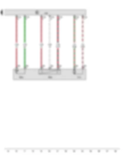
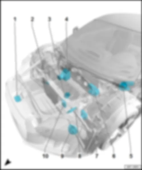
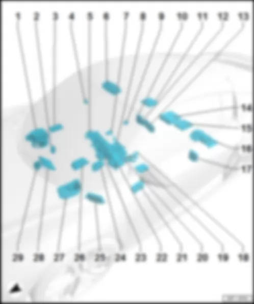
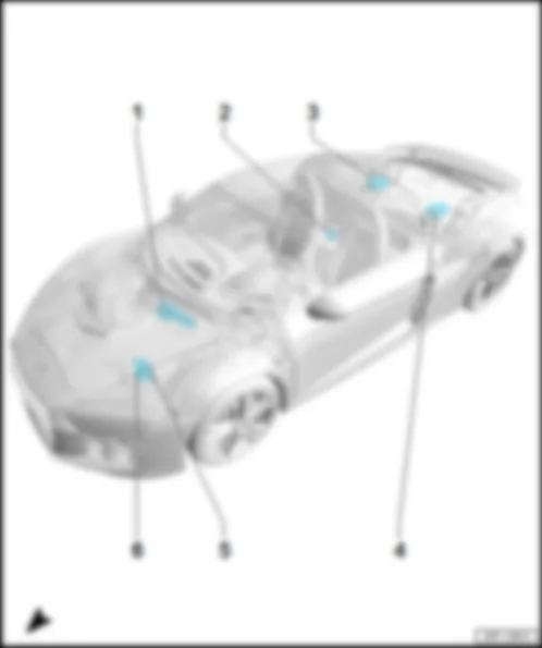
Wiring Diagram AUDI R8 2017 - All-wheel drive control unit - Data bus diagnostic interface - Fuse 1 (30) Wiring Diagram AUDI R8 2017 - Hydraulic pressure sender for all-wheel drive - Hydraulic temperature sender for all-wheel drive - All-wheel drive control unit - Haldex coupling pump AUDI R8 2017 Overview of control units in front part of vehicle 6 - Front passenger side wiper motor control unit -J584-
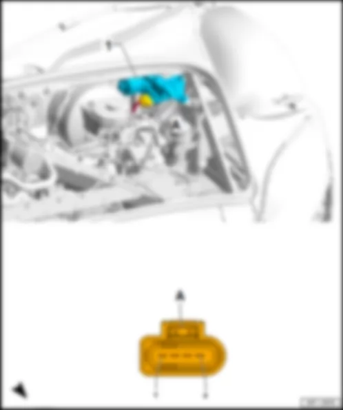
Output module 1 for left LED headlight -A31-/output module 1 for right LED headlight -A27-
q on front left headlight -MX1-/front right headlight -MX2-
q Connector assignment, LED without laser light
q Connector assignment, LED with laser light
Output module 2 for left LED headlight -A32-/output module 2 for right LED headlight -A28-
q
q Connector assignment, LED without laser light
q Connector assignment, LED with laser light
Radiator fan control unit -J293-/-J671-
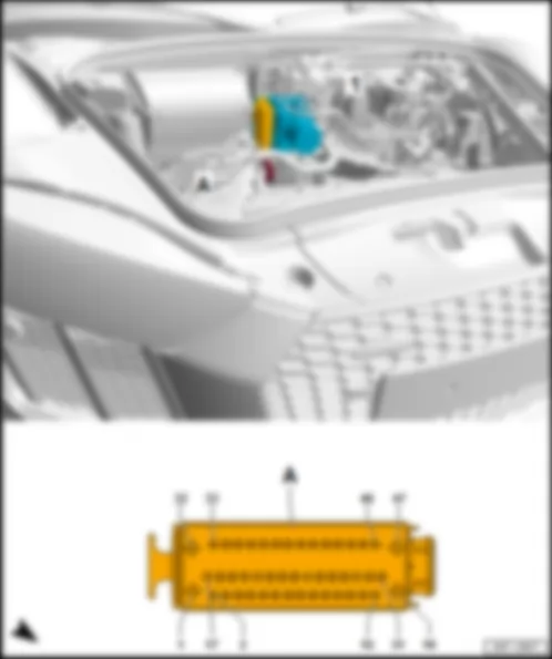
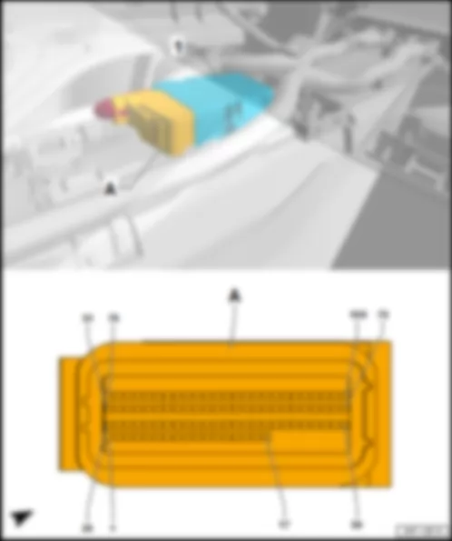
AUDI R8 2017 Fitting location, ABS control unit J104
Centred in front of the bulkhead behind the luggage compartment lining.
1 - ABS control unit -J104-
q with ABS hydraulic unit -N55-
Connector assignment, ABS control unit -J104-
-T47a- (A) Designation -T47a- (A) Designation 1 Terminal 30, from fuse 3 -S133- on main fuse carrier 25 Running gear sensors CAN bus low, to B664 connection (running gear sensors CAN bus low) in main wiring harness 2 26 Front right speed sensor -G45- 3 FlexRay bus, from data bus diagnostic interface -J533- 27 Front left speed sensor -G47- 4 28 5 29 Rear left speed sensor -G46- 6 30 7 Vacuum sender -G608- 31 Vacuum sender -G608- 8 32 Terminal 30, from fuse carrier 5 -ST5- in fuse holder C -SC- 9 Vacuum sender -G608- 33 10 34 11 Front left speed sensor -G47- 35 12 36 ASR/ESP button -E256- in switch module in centre of dash panel -EX22- 13 Rear left speed sensor -G46- 37 14 Terminal 15, from fuse carrier 1 -ST1- in fuse holder C -SC- 38 15 39 16 Terminal 31, to 686 earth point 2 on front of right side member 40 Running gear sensors CAN bus high, to B663 connection (running gear sensors CAN bus high) in main wiring harness 17 41 Front right speed sensor -G45- 18 42 19 FlexRay bus, from data bus diagnostic interface -J533- 43 Rear right speed sensor -G44- 20 44 Rear right speed sensor -G44- 21 45 Terminal 30, from fuse carrier 5 -ST5- in fuse holder C -SC- 22 46 23 47 Terminal 31, to 686 earth point 2 on front of right side member 24
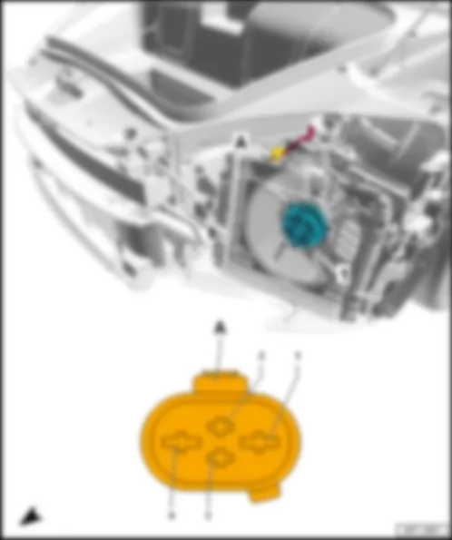
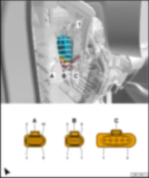
AUDI R8 2017 Fitting location, radiator fan control unit J293 / J671
On front left/right radiator.
1 - Radiator fan control unit -J293-/-J671-
q on front left radiator: radiator fan control unit -J293-
q on front right radiator: radiator fan control unit 2 -J671-
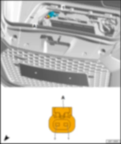
4-pin connector -T4v-/-T4y-, black
q Radiator fan control unit -J293-: -T4v-
q Radiator fan control unit 2 -J671-: -T4y-
-T4v- (A) Designation -T4y- (A) Designation 1 Terminal 30, from radiator fan single fuse -S42- on cover for main fuse carrier 1 Terminal 30, from radiator fan fuse for 2nd speed -S104- cover for main fuse carrier 2 Terminal 87, from fuse holder A -SA- 2 Terminal 87, from fuse holder A -SA- 3 Fan stage, from engine control unit -J623- 3 Fan stage, from engine control unit -J623- 4 Terminal 31, to 671 earth point 1 on front side member, left 4 Terminal 31, to 685 earth point 1 on front of right side member
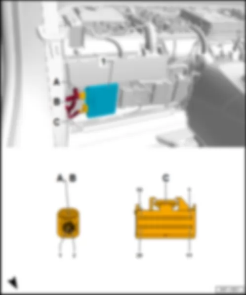
AUDI R8 2017 Fitting location, battery monitor control unit J367
At negative terminal of battery -A-.
1 - Battery monitor control unit -J367-
Connector assignment, battery monitor control unit -J367-
-T2bv- (A) Designation 1 LIN bus, from B528 connection 1 (LIN bus) in main wiring harness 2 from connection G1 on main fuse carrier
AUDI R8 2017 Fitting location, control unit for wiper motor J400
On the driver side in the wheel housing under the wheel housing liner.
1 - Wiper motor control unit -J400-
Connector assignment, wiper motor control unit -J400-
-T4t- (A) Designation 1 LIN bus, to B711 connection 6 (LIN bus) in main wiring harness 2 Front passenger side wiper motor control unit -J584- 3 Terminal 31, to 646 earth point 2 on bulkhead 4 Terminal 30, from fuse carrier 4 -ST4- in fuse holder C -SC-
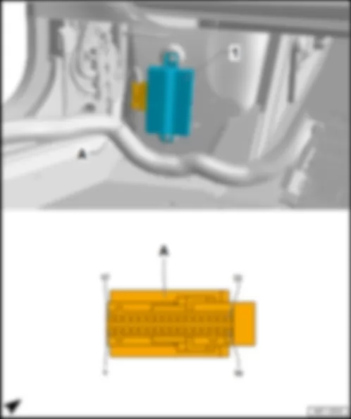
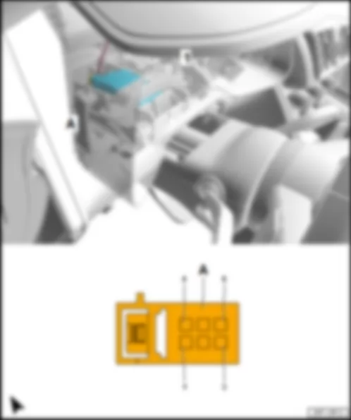
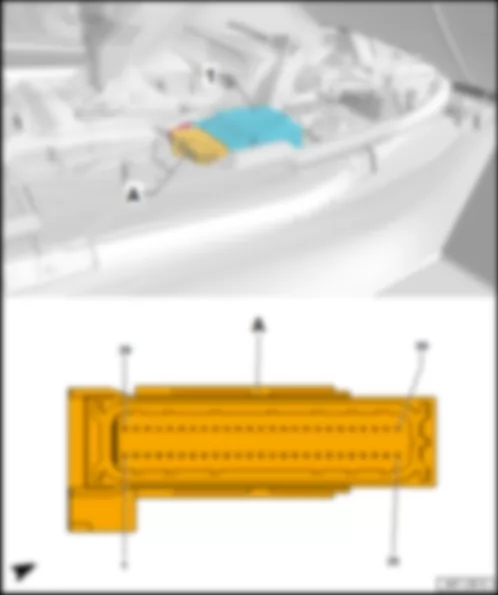
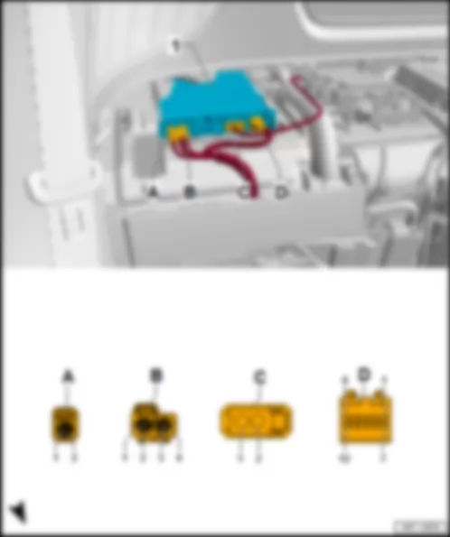
AUDI R8 2017 Fitting location, all-wheel drive control unit J492
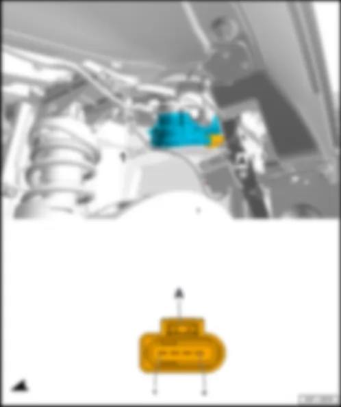
On main fuse box on left next to battery -A-.
1 - All-wheel drive control unit -J492-
B - 9-pin connector -T9f-, grey
-T12a- (A) Designation -T9f- (B) Designation 1 1 Terminal 30, from fuse 1 (30) -S204- on cover of main fuse carrier 2 Clutch temperature sender -G509- 2 3 Clutch temperature sender -G509- 3 Running gear sensors CAN bus high, to B663 connection (running gear sensors CAN bus high) in main wiring harness 4 4 5 5 6 Clutch pressure sender 1 -G662- 6 Running gear sensors CAN bus low, to B664 connection (running gear sensors CAN bus low) in main wiring harness 7 7 Terminal 31, to 646 earth point 2 on bulkhead 8 Clutch pressure sender 1 -G662- 8 9 Clutch pressure sender 1 -G662- 9 Terminal 15, from fuse carrier 1 -ST1- in fuse holder C -SC- 10 11 Haldex coupling pump -V181- 12 Haldex coupling pump -V181-
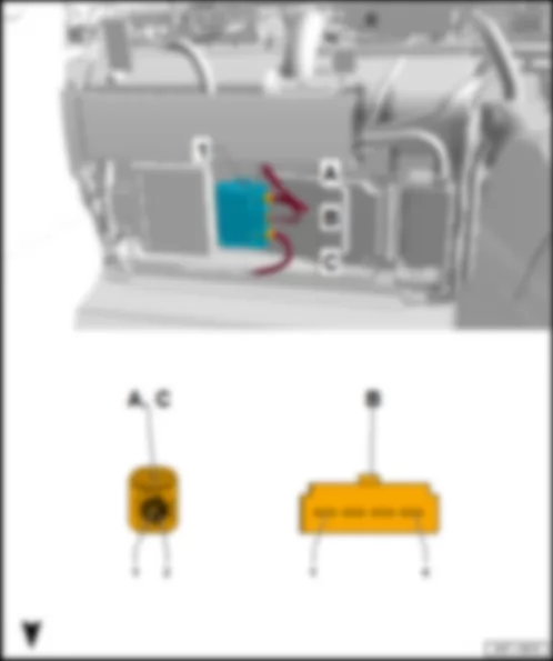
AUDI R8 2017 Fitting location, power steering control unit J500
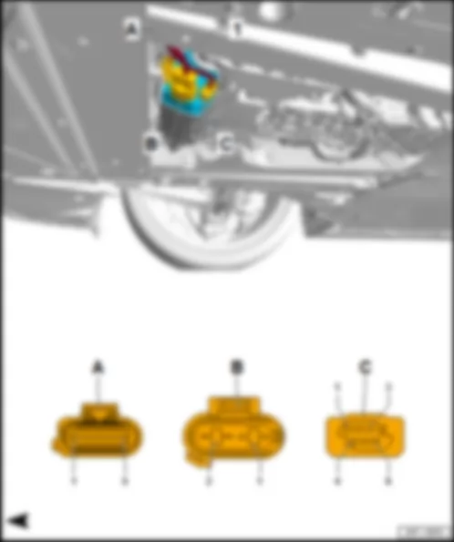
1 - Power steering control unit -J500-
q Components: Steering angle sensor -G85-, steering torque sensor -G269-, electromechanical power steering motor -V187-
C - 2-pin connector -T2ck-, black
Connector assignment, power steering control unit -J500-
-T2ck- (B) Designation -T6e- (C) Designation 1 Terminal 30, from coupling point on right in engine compartment -TMR- 1 2 Terminal 31, to 672 earth point 2 on front side member, left 2 Running gear sensors low CAN bus, from B664 connection (running gear sensors low CAN bus) in main wiring harness 3 4 5 Running gear sensors high CAN bus, from B663 connection (running gear sensors high CAN bus) in main wiring harness 6 Terminal 15, from fuse carrier 3 -ST3- in fuse holder C -SC-
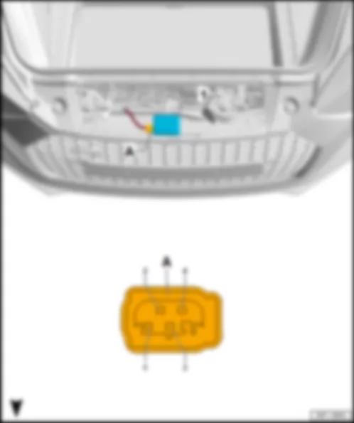
AUDI R8 2017 Fitting location, garage door operation control unit J530
Centred on the front bumper mount.
1 - Garage door operation control unit -J530-
Connector assignment, garage door operation control unit -J530-
-T4u- (A) Designation 1 2 LIN bus, from B549 connection 2 (LIN bus) in main wiring harness 3 Terminal 31, to 685 earth point 1 on front of right side member 4 Terminal 30, from fuse carrier 1 -ST1- in fuse holder C -SC-
AUDI R8 2017 Fitting location, front passenger side wiper motor control unit J584
On the driver side in front of the bulkhead on the left next to the brake servo behind the luggage compartment lining.
1 - Front passenger side wiper motor control unit -J584-
Connector assignment, front passenger side wiper motor control unit -J584-
-T4cq- (A) Designation 1 Terminal 30, from fuse carrier 4 -ST4- in fuse holder C -SC- 2 Terminal 31, to 646 earth point 2 on bulkhead 3 Wiper motor control unit -J400- 4
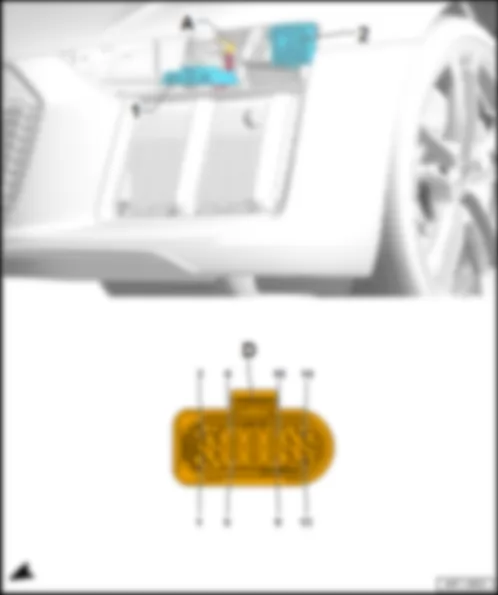
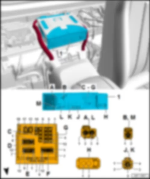
AUDI R8 2017 Fitting location, control units on front headlight MX1 / MX2
1 - Output module 2 for right LED headlight -A28-/output module 2 for left LED headlight -A32-
- Output module 1 for right LED headlight -A27-/output module 1 for left LED headlight -A31-
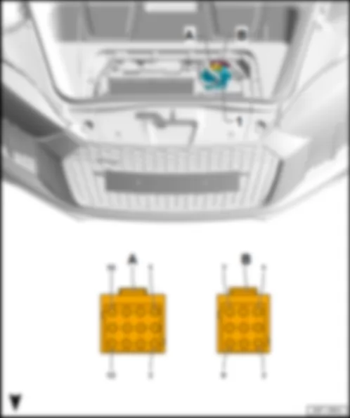
14-pin connector -T14h-/-T14i-, black
q Right headlight: -T14i-
-T14h- (A) Designation -T14i- (A) Designation 1 Headlight CAN bus high, to headlight range control unit -J431- 1 Headlight CAN bus high, to headlight range control unit -J431- 2 Headlight CAN bus high, to headlight range control unit -J431- 2 Headlight CAN bus high, to headlight range control unit -J431- 3 3 4 4 5 Terminal 31, to 671 earth point 1 on front side member, left 5 Terminal 31, to 685 earth point 1 on front of right side member 6 Onboard supply control unit -J519- 6 Onboard supply control unit -J519- 7 7 8 Onboard supply control unit -J519- 8 Onboard supply control unit -J519- 9 Terminal 15, from fuse carrier 1 -ST1- in fuse holder C -SC- 9 Terminal 15, from fuse carrier 1 -ST1- in fuse holder C -SC- 10 Terminal 31, to 671 earth point 1 on front side member, left 10 Terminal 31, to 685 earth point 1 on front of right side member 11 Onboard supply control unit -J519- 11 Onboard supply control unit -J519- 12 Onboard supply control unit -J519- 12 Onboard supply control unit -J519- 13 Onboard supply control unit -J519- 13 Onboard supply control unit -J519- 14 14
-T14h- (A) Designation -T14i- (A) Designation 1 Headlight CAN bus high, to headlight range control unit -J431- 1 Headlight CAN bus high, to headlight range control unit -J431- 2 Headlight CAN bus high, to headlight range control unit -J431- 2 Headlight CAN bus high, to headlight range control unit -J431- 3 Onboard supply control unit -J519- 3 Onboard supply control unit -J519- 4 Sequential indicator coding lead, to B467 connection 3 in main wiring harness 4 Sequential indicator coding lead, to B467 connection 3 in main wiring harness 5 Terminal 31, to 671 earth point 1 on front side member, left 5 Terminal 31, to 377 earth connection 12 in main wiring harness 6 Onboard supply control unit -J519- 6 Onboard supply control unit -J519- 7 Onboard supply control unit -J519- 7 Onboard supply control unit -J519- 8 Terminal 15, from fuse carrier 1 -ST1- in fuse holder C -SC- 8 Terminal 15, from fuse carrier 1 -ST1- in fuse holder C -SC- 9 Onboard supply control unit -J519- 9 Onboard supply control unit -J519- 10 Terminal 31, to 671 earth point 1 on front side member, left 10 Terminal 31, to 685 earth point 1 on front of right side member 11 Onboard supply control unit -J519- 11 Onboard supply control unit -J519- 12 Onboard supply control unit -J519- 12 Onboard supply control unit -J519- 13 Onboard supply control unit -J519- 13 Onboard supply control unit -J519- 14 LIN bus, to B710 connection 5 (LIN bus) in main wiring harness 14 LIN bus, to B710 connection 5 (LIN bus) in main wiring harness
AUDI R8 2017 Overview of control units in middle part of vehicle Seat and steering column adjustment control unit with memory -J136- /front passenger seat adjustment control unit with memory -J521-
q Connector assignment, seat and steering column adjustment control unit with memory -J136-
q Connector assignment, front passenger seat adjustment control unit with memory -J521-
Door control unit -J386- /-J387-
q Connector assignment, driver door control unit -J386-
q Connector assignment, front passenger door control unit -J387-
q Fitting location, right-hand drive models
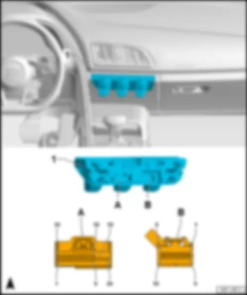
AUDI R8 2017 Fitting location Operating and display unit for Climatronic air conditioning system E87
1 - Operating and display unit for Climatronic air conditioning system -E87-
B - 16-pin connector -T16i- , brown
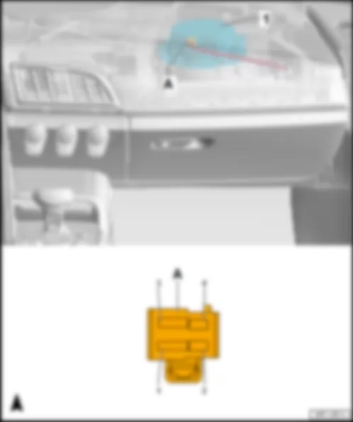
AUDI R8 2017 Fitting location, fresh air blower control unit J126
Behind the glove component on front heater and air conditioner unit.
1 - Fresh air blower control unit -J126-
Connector assignment, fresh air blower control unit -J126-
-T4ar- (A) Designation 1 Terminal 31, to 638 earth point on right A-pillar 2 3 Terminal 30, from fuse carrier 2 -ST2- in fuse holder C -SC- 4 LIN bus, from operating and display unit for Climatronic air conditioning system -E87-
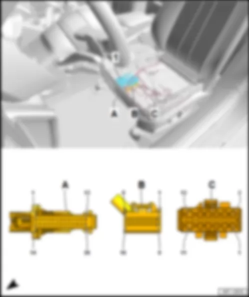
AUDI R8 2017
1 - Seat and steering column adjustment control unit with memory -J136- /front passenger seat adjustment control unit with memory -J521-
26-pin connector -T26b- /-T26c- , black
q 26-pin connector -T26b- on seat and steering column adjustment control unit with memory -J136-
q 26-pin connector -T26c- on front passenger seat adjustment control unit with memory -J521-
16-pin connector -T16k- /-T16l- , black
q 16-pin connector -T16k- on seat and steering column adjustment control unit with memory -J136-
q 16-pin connector -T16l- on front passenger seat adjustment control unit with memory -J521-
12-pin connector -T12n- /-T12o- , black
q 12-pin connector -T12n- on seat and steering column adjustment control unit with memory -J136-
q 12-pin connector -T12o- on front passenger seat adjustment control unit with memory -J521-
-T26b- (A) Designation -T26b- (A) Designation 1 Valve for upper air cushion of driver side lumbar support -N715- 14 2 Valve for upper air cushion of driver side lumbar support -N715- 15 3 Valve for lower air cushion of driver side lumbar support -N714- 16 4 Valve for lower air cushion of driver side lumbar support -N714- 17 Earth supply for valves -N716- /-N717- 5 Earth supply for valves -N714- /-N715- and pressure sensors -G945- /-G946- 18 Earth line, to 140 earth connection 2 in seat adjustment wiring harness 6 19 Seat depth adjustment sender -G378- 7 Positive supply for pressure sensors -G945- /-G946- 20 Longitudinal adjustment sender for driver seat -G218- 8 Compressor for multicontour driver seat -V439- 21 Driver seat rake adjustment sender -G232- 9 Compressor for multicontour driver seat -V439- 22 Driver seat height adjustment sender -G231- 10 Valve for air cushion of backrest side bolsters on driver side -N717- 23 Backrest adjustment sender for driver seat -G219- 11 Valve for air cushion of backrest side bolsters on driver side -N717- 24 12 Valve for air cushion of seat bolsters on driver side -N716- 25 Pressure sensor 2 in driver seat -G946- 13 Valve for air cushion of seat bolsters on driver side -N716- 26 Pressure sensor 1 in driver seat -G945-
-T16k- (B) Designation -T12n- (C) Designation 1 Driver seat rake adjustment switch -E222- in driver seat adjustment operating unit -E470- 1 Driver seat rake adjustment motor -V243- 2 Driver seat height adjustment switch -E364- in driver seat adjustment operating unit -E470- 2 Driver seat rake adjustment motor -V243- 3 Driver seat backrest adjustment switch -E96- in driver seat adjustment operating unit -E470- 3 Driver seat longitudinal adjustment motor -V28- 4 Coding lead, to contact 12 in connector -T16k- 4 Driver seat longitudinal adjustment motor -V28- 5 Comfort low CAN bus to B406 connection 1 (comfort low CAN bus) in main wiring harness 5 Driver seat backrest adjustment motor -V45- 6 Comfort high CAN bus, to B397 connection 1 (comfort high CAN bus) in main wiring harness 6 Driver seat backrest adjustment motor -V45- 7 7 Driver seat height adjustment motor -V245- 8 8 Driver seat height adjustment motor -V245- 9 Seat depth adjustment button -E350- in driver seat adjustment operating unit -E470- 9 Driver seat depth adjustment motor -V256- 10 Driver seat longitudinal adjustment switch -E363- in driver seat adjustment operating unit -E470- 10 Driver seat depth adjustment motor -V256- 11 Earth line, to M10 connection 1 in driver seat adjustment wiring harness 11 Terminal 31, to 639 earth point on left A-pillar 12 Coding lead, to contact 4 in connector -T16k- 12 Terminal 30, from driver seat adjustment thermal fuse 1 -S44- on relay and fuse carrier 3 -SR3- 13 Lumbar support height adjustment button -E335- in switch module for driver seat -E663- 14 Lumbar support longitudinal adjustment button -E336- in switch module for driver seat -E663- 15 Driver seat bolster adjustment button -E587- in switch module for driver seat -E663- 16 Driver seat backrest side bolster adjustment button -E589- in switch module for driver seat -E663-
-T26c- (A) Designation -T26c- (A) Designation 1 Valve for upper air cushion of front passenger side lumbar support -N719- 14 2 Valve for upper air cushion of front passenger side lumbar support -N719- 15 3 Valve for lower air cushion of front passenger side lumbar support -N718- 16 4 Valve for lower air cushion of front passenger side lumbar support -N718- 17 Earth supply for valves -N720- /-N721- 5 Earth supply for valves -N718- /-N719- and pressure sensors -G947- /-G948- 18 Earth line, to 413 earth connection 4 in seat adjustment wiring harness 6 19 Front passenger seat depth adjustment sender -G724- 7 Positive supply for pressure sensors -G947- /-G948- 20 Longitudinal adjustment sender for front passenger seat -G278- 8 Compressor for multicontour front passenger seat -V440- 21 Front passenger seat rake adjustment sender -G359- 9 Compressor for multicontour front passenger seat -V440- 22 Front passenger seat height adjustment sender -G607- 10 Valve for air cushion of backrest side bolsters on front passenger side -N721- 23 Backrest adjustment sender for front passenger seat -G279- 11 Valve for air cushion of backrest side bolsters on front passenger side -N721- 24 12 Valve for air cushion of seat bolsters on front passenger side -N720- 25 Pressure sensor 2 in front passenger seat -G948- 13 Valve for air cushion of seat bolsters on front passenger side -N720- 26 Pressure sensor 1 in front passenger seat -G947-
-T16l- (B) Designation -T12o- (C) Designation 1 Front passenger seat rake adjustment button -E334- in front passenger seat adjustment operating unit -E471- 1 Front passenger seat rake adjustment motor -V244- 2 Front passenger seat height adjustment switch -E365- in front passenger seat adjustment operating unit -E471- 2 Front passenger seat rake adjustment motor -V244- 3 Front passenger seat backrest adjustment switch -E98- in front passenger seat adjustment operating unit -E471- 3 Front passenger seat longitudinal adjustment motor -V31- 4 Coding lead, to contact 12 in connector -T16l- 4 Front passenger seat longitudinal adjustment motor -V31- 5 Comfort low CAN bus to B407 connection 2 (comfort low CAN bus) in main wiring harness 5 Front passenger seat backrest adjustment motor -V46- 6 Comfort high CAN bus, to B398 connection 2 (comfort high CAN bus) in main wiring harness 6 Front passenger seat backrest adjustment motor -V46- 7 7 Front passenger seat height adjustment motor -V246- 8 8 Front passenger seat height adjustment motor -V246- 9 Front passenger seat depth adjustment button -E867- in front passenger seat adjustment operating unit -E471- 9 Front passenger seat depth adjustment motor -V257- 10 Front passenger seat longitudinal adjustment switch -E64- in front passenger seat adjustment operating unit -E471- 10 Front passenger seat depth adjustment motor -V257- 11 Earth line, to M18 connection 1 in front passenger seat adjustment wiring harness 11 Terminal 31, to 751 earth point 2 on right A-pillar 12 Coding lead, to contact 4 in connector -T16l- 12 Terminal 30, from front passenger seat adjustment thermal fuse 1 -S46- on relay and fuse carrier 3 -SR3- 13 Front passenger side lumbar support height adjustment button -E882- in switch module for front passenger seat -E664- 14 Front passenger side lumbar support longitudinal adjustment button -E883- in switch module for front passenger seat -E664- 15 Front passenger seat bolster adjustment button -E588- in switch module for front passenger seat -E664- 16 Front passenger seat backrest side bolster adjustment button -E590- in switch module for front passenger seat -E664-
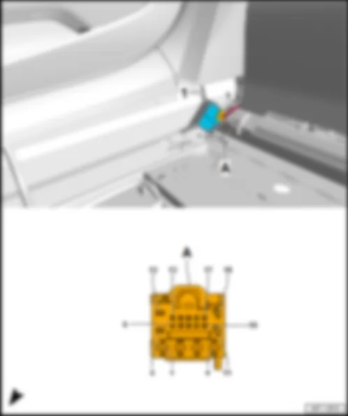
AUDI R8 2017 Fitting location, adjustable rear spoiler control unit J223
On the right sill right at the back in front of the rear wall.
1 - Adjustable rear spoiler control unit -J223-
Connector assignment, adjustable rear spoiler control unit -J223-
-T18a- (A) Designation -T18a- (A) Designation 1 10 Rear spoiler -VX73- 2 Rear spoiler adjustment motor -V52- in rear spoiler -VX73- 11 Limit switch 1 for rear spoiler adjustment -F135- in rear spoiler -VX73- 3 Terminal 31, to 35 earth point under front passenger seat 12 Rear spoiler adjustment switch -E127- in switch module in centre of dash panel -EX22- 4 Terminal 30, from fuse carrier 2 -ST2- in fuse holder D -SD- 13 5 Rear spoiler adjustment motor -V52- in rear spoiler -VX73- 14 6 Rear spoiler adjustment switch -E127- in switch module in centre of dash panel -EX22- 15 7 LIN bus, from convenience system central control unit -J393- 16 8 17 Limit switch 2 for rear spoiler adjustment -F136- in rear spoiler -VX73- 9 18 Rear spoiler -VX73-
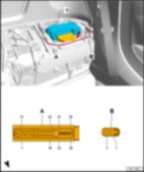
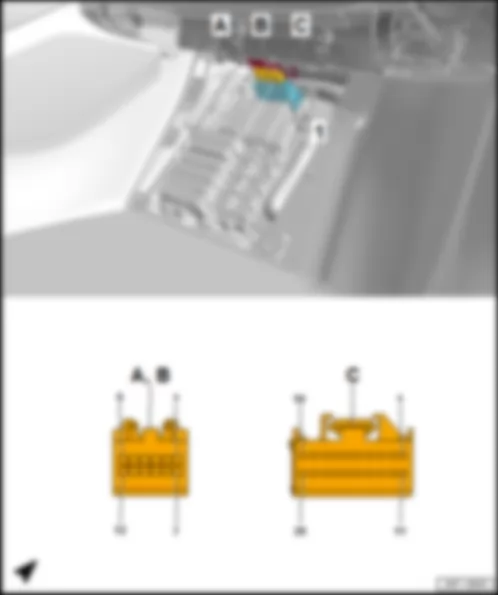
AUDI R8 2017 Fitting location, airbag control unit J234
Under centre console at front on centre tunnel
1 - Airbag control unit -J234-
100-pin connector -T100a- , yellow
AUDI R8 2017 Fitting location, electronically controlled damping control unit J250
Under the rear shelf at the bottom right on the rear wall next to the centre tunnel.
1 - Electronically controlled damping control unit -J250-
Connector assignment, electronically controlled damping control unit -J250-
-T47b- (A) Designation -T47b- (A) Designation -T47b- (A) Designation 1 Terminal 15, from fuse carrier 2 -ST21- in fuse holder D -SD- 17 Rear left vehicle level sender -G76- 33 Rear left vehicle level sender -G76- 2 Rear left vehicle level sender -G76- 18 Front right vehicle level sender -G289- 34 Front right vehicle level sender -G289- 3 Front right vehicle level sender -G289- 19 35 Rear right vehicle level sender -G77- 4 20 Rear right vehicle level sender -G77- 36 Front left vehicle level sender -G78- 5 Rear right vehicle level sender -G77- 21 Front left vehicle level sender -G78- 37 Running gear sensors CAN bus low, to B783 connection 2 (running gear sensors CAN bus low) in main wiring harness 6 Front left vehicle level sender -G78- 22 38 Running gear sensors CAN bus high, to B773 connection 2 (running gear sensors CAN bus high) in main wiring harness 7 23 39 8 24 40 9 25 41 10 26 42 Rear left shock absorber damping adjustment valve -N338- 11 27 Front right shock absorber damping adjustment valve -N337- 43 Rear left shock absorber damping adjustment valve -N338- 12 28 Front right shock absorber damping adjustment valve -N337- 44 13 29 45 Rear right shock absorber damping adjustment valve -N339- 14 30 Front left shock absorber damping adjustment valve -N336- 46 Rear right shock absorber damping adjustment valve -N339- 15 31 Front left shock absorber damping adjustment valve -N336- 47 Terminal 30, from fuse carrier 1 -ST1- in fuse holder D -SD- 16 Terminal 31, to 35 earth point under front passenger seat 32
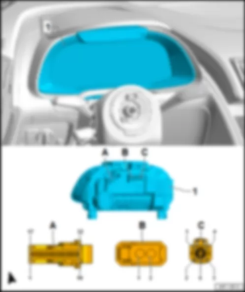
AUDI R8 2017 Fitting location, control unit in dash panel insert J285
In driver side dash panel.
1 - Control unit in dash panel insert -J285-
B - 2-pin connector -T2ee- , black
Connector assignment, control unit in dash panel insert -J285-
-T32k- (A) Designation -T32k- (A) Designation -T32k- (A) Designation 1 Ring break diagnosis, to B444 connection 1 (diagnosis) in main wiring harness 12 23 2 13 24 3 Dash panel insert CAN bus low, to A205 connection (dash panel insert CAN bus low) in dash panel wiring harness 14 25 CAN bus, control unit 1 for information electronics, low, to E147 connection 1 (CAN bus, control unit 1 for information electronics, low) 4 Dash panel insert CAN bus high, to A204 connection (dash panel insert CAN bus high) in dash panel wiring harness 15 26 CAN bus, control unit 1 for information electronics, high, to E145 connection 1 (CAN bus, control unit 1 for information electronics, high) 5 Earth supply for fuel level sender 16 27 6 Fuel gauge sender -G- 17 28 7 Fuel level sender 2 -G169- 18 29 8 Dash panel insert operating buttons -E493- 19 30 Terminal 31, to 664 earth point on left behind dash panel 9 Fuel level sender 3 -G237- 20 31 10 Fuel level sender 4 -G393- 21 32 Terminal 30, from fuse carrier 3 -ST3- in fuse holder C -SC- 11 22
AUDI R8 2017
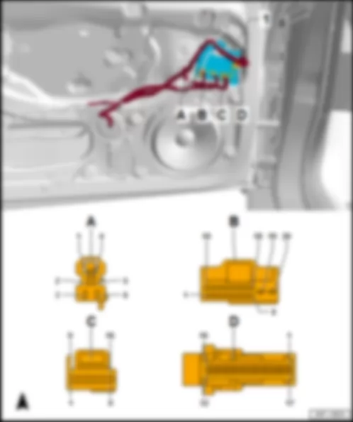
In driver door/front passenger door.
1 - Driver door control unit -J386- /front passenger door control unit -J387-
6-pin connector -T6m- /-T6n- , black
q Driver door control unit -J386- : -T6m-
q Front passenger door control unit -J387- : -T6n-
20-pin connector -T20b- /-T20c- , black
q Driver door control unit -J386- : -T20b-
q Front passenger door control unit -J387- : -T20c-
16-pin connector -T16g- /-T16h- , black
q Driver door control unit -J386- : -T16g-
q Front passenger door control unit -J387- : -T16h-
32-pin connector -T32h- /-T32i- , blue
q Driver door control unit -J386- : -T32h-
q Front passenger door control unit -J387- : -T32i-
-T6m- (A) Designation -T20b- (B) Designation 1 1 Contact switch in driver side locking cylinder -F241- in driver side locking unit for central locking -F220- 2 2 Microswitch for lowering driver window -E621- 3 Driver side window regulator motor -V147- 3 4 4 5 5 Driver door contact switch -F2- in driver side locking unit for central locking -F220- 6 Driver side window regulator motor -V147- 6 Front left central locking actuator -F131- in driver side locking unit for central locking -F220- 7 8 Mirror dimming signal line, to B427 connection 1 (mirror signal) in main wiring harness 9 10 11 Motor for central locking SAFE function in driver door -V161- /driver side motor for central locking -V503- in driver side locking unit for central locking -F220- 12 Motor for central locking SAFE function in driver door -V161- in driver side locking unit for central locking -F220- 13 Driver side motor for central locking -V503- in driver side locking unit for central locking -F220- 14 Comfort low CAN bus to B406 connection 1 (comfort low CAN bus) in main wiring harness 15 Comfort high CAN bus, to B397 connection 1 (comfort high CAN bus) in main wiring harness 16 17 Mirror dimming signal line, to B428 connection 2 (mirror signal) in main wiring harness 18 19 Terminal 30, from fuse carrier 5 -ST5- in fuse holder C -SC- 20 Terminal 31, to 639 earth point on left A-pillar
-T16g- (C) Designation -T32h- (D) Designation 1 1 Central locking SAFELOCK function warning lamp -K133- 2 Driver side automatic anti-dazzle exterior mirror -Y20- 2 3 Earth line, to 107 earth connection in exterior mirror wiring harness 3 Driver side door interior handle illumination bulb -L146- 4 4 Switch lights, to R95 connection 2 in driver door wiring harness 5 Earth supply for driver side mirror adjustment motors 5 Earth line, to 205 earth connection in driver door wiring harness 6 Driver side automatic anti-dazzle exterior mirror -Y20- 6 7 Driver side mirror adjustment motor -V149- 7 8 Driver side mirror adjustment motor -V17- 8 9 Driver side fold-in mirror motor -V121- 9 10 Driver side fold-in mirror motor -V121- 10 Alarm system off switch -E217- 11 Driver side turn signal repeater bulb in exterior mirror -L131- 11 12 12 13 13 Driver side interior locking button for central locking system -E308- 14 14 15 Heated exterior mirror on driver side -Z4- 15 16 16 Terminal 58, to R65 positive connection (58) in driver door wiring harness 17 18 19 20 Alarm system off switch -E217- 21 22 23 Rear lid remote release button -E233- 24 Mirror adjustment switch -E43- 25 Mirror adjustment changeover switch -E48- 26 27 28 Driver side interior locking button for central locking system -E308- 29 30 31 Front right window regulator switch in driver door -E81- in window regulator operating unit in driver door -E512- 32 Front left window regulator switch -E40- in window regulator operating unit in driver door -E512-
-T6n- (A) Designation -T20c- (B) Designation 1 1 2 2 Microswitch for lowering front passenger window -E622- 3 Front passenger side window regulator motor -V148- 3 4 4 5 5 Front passenger door contact switch -F3- in front passenger side locking unit for central locking -F221- 6 Front passenger side window regulator motor -V148- 6 Front right central locking actuator -F133- in front passenger side locking unit for central locking -F221- 7 8 Mirror dimming signal line, to B427 connection 1 (mirror signal) in main wiring harness 9 10 11 Front passenger side motor for central locking -V504- in front passenger side locking unit for central locking -F221- 12 Motor for central locking SAFE function in front passenger door -V162- in front passenger side locking unit for central locking -F221- 13 Motor for central locking SAFE function in front passenger door -V162- /front passenger side motor for central locking -V504- in front passenger side locking unit for central locking -F221- 14 Comfort low CAN bus to B407 connection 2 (comfort low CAN bus) in main wiring harness 15 Comfort high CAN bus, to B398 connection 2 (comfort high CAN bus) in main wiring harness 16 17 Mirror dimming signal line, to B428 connection 2 (mirror signal) in main wiring harness 18 19 Terminal 30, from fuse carrier 5 -ST5- in fuse holder C -SC- 20 Terminal 31, to 751 earth point 2 on right A-pillar
-T16h- (C) Designation -T32i- (D) Designation 1 1 2 Front passenger side automatic anti-dazzle exterior mirror -Y21- 2 3 Earth line, to 107 earth connection in exterior mirror wiring harness 3 Front passenger side door interior handle illumination bulb -L147- 4 4 Switch lights, to R99 connection 2 in front passenger door wiring harness 5 Earth supply for front passenger side mirror adjustment motor 5 Earth line, to 268 earth connection 2 in front passenger door wiring harness 6 Front passenger side automatic anti-dazzle exterior mirror -Y21- 6 7 Front passenger side mirror adjustment motor -V150- 7 8 Front passenger side mirror adjustment motor -V25- 8 9 Front passenger side fold-in mirror motor -V122- 9 10 Front passenger side fold-in mirror motor -V122- 10 11 Front passenger side turn signal repeater bulb in exterior mirror -L132- 11 12 12 13 13 Front passenger side interior locking button for central locking system -E309- 14 14 15 Heated exterior mirror on front passenger side -Z5- 15 16 16 Terminal 58, to R67 positive connection (58) in front passenger door wiring harness 17 18 19 20 21 22 23 24 25 26 27 28 Front passenger side interior locking button for central locking system -E309- 29 30 31 32 Front passenger side window regulator button -E716-
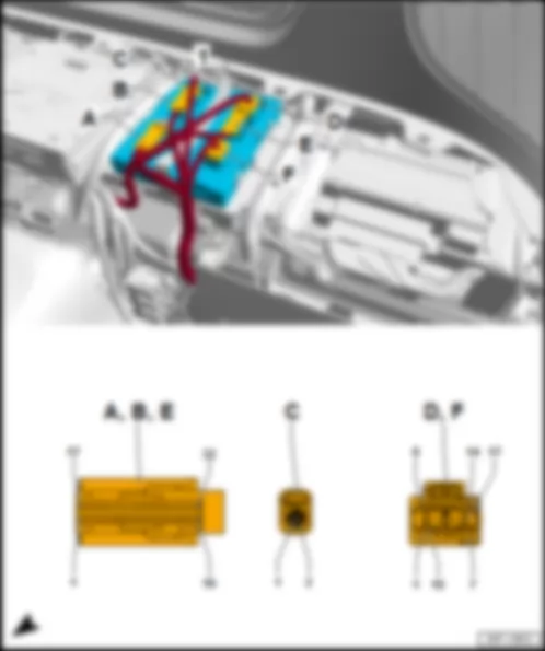
AUDI R8 2017 Fitting location, convenience system central control unit J393
Under the rear shelf on the rear wall on the left next to the control unit 1 for information electronics -J794- .
1 - Convenience system central control unit -J393-
B - 32-pin connector -T32e- , grey
D - 17-pin connector -T17k- , black
F - 17-pin connector -T17l- , brown
-T32f- (A) Designation -T32e- (B) Designation 1 1 2 2 Brake light signal, from brake light switch -F- 3 3 4 4 Front lid contact switch -F387- 5 5 Engine control unit -J623- 6 6 7 7 8 8 9 Left aerial for entry and start authorisation -R200- 9 10 Left aerial for entry and start authorisation -R200- 10 11 Luggage compartment aerial for entry and start system -R137- 11 12 Luggage compartment aerial for entry and start system -R137- 12 Steering column electronics control unit -J527- 13 Right aerial for entry and start authorisation -R201- 13 Steering column electronics control unit -J527- 14 Right aerial for entry and start authorisation -R201- 14 15 Interior aerial 1 for entry and start system -R138- 15 Control unit for electronic steering column lock -J764- 16 Interior aerial 1 for entry and start system -R138- 16 Terminal 15 voltage supply relay -J329- 17 17 18 18 Additional brake light bulb -M25- 19 19 Sequential indicator coding lead, to B474 connection 10 in main wiring harness 20 20 Steering column electronics control unit -J527- 21 21 22 22 23 23 24 24 25 25 26 26 27 27 28 28 Selector position P/N line, from mechatronic unit for dual clutch gearbox -J743- 29 29 30 Contact sensor for front right exterior door handle -G606- 30 31 31 32 Contact sensor for front left exterior door handle -G605- 32
-T17k- (D) Designation -T32d- (E) Designation -T17l- (F) Designation 1 1 1 2 2 2 3 3 Button for emergency luggage compartment release -E596- 3 4 4 Heated rear window relay -J9- 4 5 Suppression filter -C24- /front lid release motor -V394- 5 5 Left reversing light bulb -M16- in left tail light module -MX3- 6 Tank filler flap locking motor -V155- 6 6 Bulb 2 for left brake light -M86- in left tail light module -MX3- 7 Tank filler flap locking motor -V155- 7 7 8 Bulb for right brake light -M10- in right tail light module -MX4- 8 8 Luggage compartment light -W3- 9 Bulb for right tail light -M2- in right tail light module -MX4- 9 9 Left brake light bulb -M9- in left tail light module -MX3- 10 Right rear fog light bulb -L47- in right tail light module -MX4- 10 10 Left tail light bulb -M4- in left tail light module -MX3- 11 Right reversing light bulb -M17- in right tail light module -MX4- 11 11 Left rear fog light bulb -L46- in left tail light module -MX3- 12 Rear right direction indicator bulb -M8- in right tail light module -MX4- 12 12 Bulb 2 for right brake light -M87- in right tail light module -MX4- 13 13 13 Rear left direction indicator bulb -M6- in left tail light module -MX3- 14 14 Number plate light -X4- /-X5- 14 15 Terminal 30, from fuse carrier 2 -ST2- in fuse holder D -SD- 15 Relay for power sockets -J807- 15 Control unit for electronic steering column lock -J764- 16 Terminal 30, from fuse carrier 2 -ST2- in fuse holder D -SD- 16 Alarm horn -H12- 16 Terminal 30, from fuse carrier 2 -ST2- in fuse holder D -SD- 17 Terminal 31, to 35 earth point under front passenger seat 17 LIN bus, to B698 connection 3 (LIN bus) in main wiring harness 17 Terminal 31, to 758 earth point 3 on centre tunnel 18 Comfort low CAN bus to B406 connection 1 (comfort low CAN bus) in main wiring harness 19 Comfort high CAN bus, to B397 connection 1 (comfort high CAN bus) in main wiring harness 20 21 22 23 24 25 26 27 28 29 30 Rear right side marker bulb -M38- 31 Rear left side marker bulb -M37- 32 LIN bus, to B699 connection 4 (LIN bus) in main wiring harness
AUDI R8 2017 Fitting location, headlight range control unit J431
In the footwell on the front passenger side on the wheel housing under the carpet
1 - Headlight range control unit -J431-
Connector assignment, headlight range control unit -J431-
-T26a- (A) Designation -T26a- (A) Designation 1 14 2 Extended CAN bus high, to B108 connection 1 (extended CAN bus high) in main wiring harness1) /2) 15 3 Extended CAN bus low, to B109 connection 1 (extended CAN bus low) in main wiring harness1) /2) 16 4 CAN bus low, to front headlight -MX1- /-MX2- 17 5 CAN bus high, to front headlight -MX1- /-MX2- 18 6 19 7 20 8 21 9 22 10 23 Terminal 15, from fuse carrier 1 -ST1- in fuse holder C -SC- 11 24 Terminal 31, to 751 earth point 2 on right A-pillar 12 25 13 26
1) Models with main beam assist control unit -J844-
2) Models without main beam assist control unit -J844-
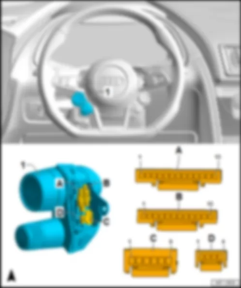
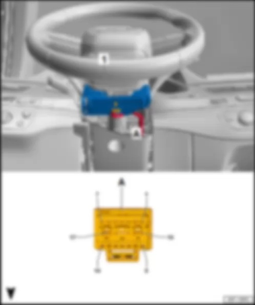
AUDI R8 2017 Fitting location, multifunction steering wheel control unit J453
Integrated on the steering wheel on the left in the damping adjustment button -E387- .
1 - Multifunction steering wheel control unit -J453-
q integrated in damping adjustment button -E387-
B - 12-pin connector -T12q- , black
q to multifunction buttons on the left in the steering wheel -E440-
D - 4-pin connector -T4da- , black
q to entry and start authorisation button -E408-
-T6ag- (C) Designation 1 LIN bus, from spring -F350- 2 Terminal 30, from spring -F350- 3 Terminal 31, from spring -F350- 4 Horn plate -H- 5 Tiptronic switch, to spring -F350- 6 Tiptronic switch, to spring -F350-
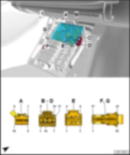
AUDI R8 2017 Fitting location, onboard supply control unit J519
In the footwell on the front passenger side above the relay and fuse carrier 3 -SR3- .
1 - Onboard supply control unit -J519-
B - 17-pin connector -T17e- , red
D - 17-pin connector -T17g- , black
F - 32-pin connector -T32b- , grey
Connector assignment, onboard supply control unit -J519-
-T16e- (A) Designation -T17e- (B) Designation -T17f- (C) Designation 1 1 1 2 LIN bus, to B711 connection 6 (LIN bus) in main wiring harness 2 Front right headlight -MX2- 2 Front left headlight -MX1- 3 Positive supply for front parking aid sender, to X65 connection (parking aid) in front bumper wiring harness 3 3 4 LIN bus, to B549 connection 2 (LIN bus) in main wiring harness 4 Front right headlight -MX2- 4 Front right side marker bulb -M34- 5 Earth supply for front and rear parking aid senders, to B468 connection 4 in main wiring harness 5 Front left headlight -MX1- 5 Front left headlight -MX1- 6 LIN bus, to B710 connection 5 (LIN bus) in main wiring harness 6 6 Front left side marker bulb -M33- 7 7 Front left headlight -MX1- 7 8 8 Front right headlight -MX2- 8 Front left headlight -MX1- 9 9 9 10 10 Front right headlight -MX2- 10 11 11 11 12 12 Front right headlight -MX2- 12 Front left headlight -MX1- 13 13 13 14 Comfort low CAN bus to B407 connection 2 (comfort low CAN bus) in main wiring harness 14 Front right headlight -MX2- 14 15 Comfort high CAN bus, to B398 connection 2 (comfort high CAN bus) in main wiring harness 15 Front right headlight -MX2- 15 Front left headlight -MX1- 16 16 Terminal 30, from fuse carrier 5 -ST5- in fuse holder C -SC- 16 Terminal 30, from fuse carrier 5 -ST5- in fuse holder C -SC- 17 Terminal 31, to 645 earth point 1 on bulkhead 17 Terminal 31, to 751 earth point 2 on right A-pillar
-T17g- (D) Designation -T17g- (D) Designation -T6f- (E) Designation 1 10 Air conditioner compressor regulating valve -N280- 1 Positive supply for driver seat heating, to O12 connection 1 in seat heating wiring harness 2 11 2 3 Washer pump -V5- 12 3 Terminal 30, from fuse carrier 5 -ST5- in fuse holder C -SC- 4 Washer pump -V5- 13 4 5 14 Positive supply for engine compartment light -W108- /-W109- 5 6 15 Terminal 30, from fuse carrier 5 -ST5- in fuse holder C -SC- 6 Positive supply for front passenger seat heating, to O13 connection 2 in seat heating wiring harness 7 16 Terminal 30, from fuse carrier 5 -ST5- in fuse holder C -SC- 8 Air conditioner compressor regulating valve -N280- 17 Terminal 30 (output), to B485 connection 21 in main wiring harness 9 Roof electronics control unit -J528-
-T32b- (F) Designation -T32a- (G) Designation 1 Parking aid button -E266- in switch module in centre of dash panel -EX22- 1 Terminal 58s, to B732 connection 2 (58s) in main wiring harness 2 Parking aid warning lamp -K136- in switch module in centre of dash panel -EX22- 2 Positive supply for rear parking aid sender, to X68 connection (parking aid) in rear bumper wiring harness 3 3 Bonnet contact switch -F266- /-F329- 4 4 Rear parking aid warning buzzer -H15- 5 5 6 Front parking aid warning buzzer -H22- 6 Brake fluid level warning contact -F34- 7 Front parking aid warning buzzer -H22- 7 Rear parking aid warning buzzer -H15- 8 Warning lamp button -E229- in switch module in centre of dash panel -EX22- 8 9 Light switch -E1- 9 Front left brake pad wear sender -G34- or front right brake pad wear sender -G35- , depending on equipment 10 10 Ambient temperature sensor -G17- 11 11 Rear left parking aid sender -G203- 12 12 Rear centre left parking aid sender -G204- 13 13 14 14 Front left seat temperature sender -G344- 15 15 Rear centre right parking aid sender -G205- 16 16 Terminal 15, from fuse carrier 1 -ST1- in fuse holder C -SC- 17 Positive supply for light -L231- /-W9- /-W10- 17 Terminal 58s, to B731 connection 1 (58s) in main wiring harness 18 Light switch -E1- 18 Rear right parking aid sender -G206- 19 19 Front right seat temperature sender -G345- 20 20 21 21 22 22 23 23 Front left parking aid sender -G255- 24 Start/stop operation warning lamp -K259- in switch module in centre of dash panel -EX22- 24 Heating resistor for spray nozzle -Z20- /-Z21- 25 25 Earth line, to 410 earth connection 1 (sender earth) in main wiring harness 26 Control unit for electronic steering column lock -J764- 26 Front centre left parking aid sender -G254- 27 27 Coolant shortage indicator sender -G32- 28 Hazard warning lights warning lamp -K6- in switch module in centre of dash panel -EX22- 28 Windscreen washer fluid level sender -G33- 29 29 Horn relay -J413- 30 Start/stop operation button -E693- in switch module in centre of dash panel -EX22- 30 Front centre right parking aid sender -G253- 31 Terminal 58s, to A175 connection (58s) in dash panel wiring harness 31 Front right parking aid sender -G252- 32 32
AUDI R8 2017 Fitting location, digital sound package control unit J525
Under the rear shelf on the rear wall on the outer left.
1 - Digital sound package control unit -J525-
C - 2-pin connector -T2ff- , black
-T38a- (A) Designation -T38a- (A) Designation -T38a- (A) Designation 1 Terminal 30, from fuse carrier 6 -ST6- in fuse holder C -SC- 14 Front right mid-range loudspeaker -R104- 27 2 Terminal 31, to 688 earth point 2 on centre tunnel 15 28 Centre loudspeaker 2 -R219- 3 16 Rear right mid-range loudspeaker -R106- 29 Internal microphone -R74- 4 Rear left mid-range loudspeaker -R105- 17 Rear right mid-range loudspeaker -R106- 30 5 Rear left mid-range loudspeaker -R105- 18 Centre loudspeaker -R208- 31 Front right treble loudspeaker -R22- 6 Centre loudspeaker -R208- 19 Front right bass loudspeaker -R23- 32 Front left treble loudspeaker -R20- 7 Front left bass loudspeaker -R21- 20 Front right bass loudspeaker -R23- 33 Rear left treble loudspeaker -R14- 8 Front left bass loudspeaker -R21- 21 34 Rear right treble loudspeaker -R16- 9 Subwoofer -R211- 22 35 10 Subwoofer -R211- 23 Front right treble loudspeaker -R22- 36 Centre loudspeaker 2 -R219- 11 Front left mid-range loudspeaker -R103- 24 Front left treble loudspeaker -R20- 37 Internal microphone -R74- 12 Front left mid-range loudspeaker -R103- 25 Rear left treble loudspeaker -R14- 38 Ring break diagnosis, to B444 connection 1 (diagnosis) in main wiring harness 13 Front right mid-range loudspeaker -R104- 26 Rear right treble loudspeaker -R16-
AUDI R8 2017 Fitting location, steering column electronics control unit J527
1 - Steering column electronics control unit -J527-
Connector assignment, steering column electronics control unit -J527-
-T17d- (A) Designation -T17d- (A) Designation 1 Terminal 30, from fuse carrier 4 -ST4- in fuse holder C -SC- 10 Convenience system central control unit -J393- 2 Terminal 15, from fuse carrier 1 -ST1- in fuse holder C -SC- 11 Airbag control unit -J234- 3 Running gear sensors CAN bus high, to B663 connection (running gear sensors CAN bus high) in main wiring harness 12 Airbag control unit -J234- 4 Running gear sensors CAN bus low, to B664 connection (running gear sensors CAN bus low) in main wiring harness 13 5 Dash panel insert CAN bus low, to B709 connection 1 (dash panel insert CAN bus low) in main wiring harness 14 6 Dash panel insert CAN bus high, to B708 connection 1 (dash panel insert CAN bus high) in main wiring harness 15 Automatic gearbox control unit 2 -J1006- 7 Engine control unit -J623- 16 Automatic gearbox control unit 2 -J1006- 8 Convenience system central control unit -J393- 17 Terminal 31, to 687 earth point 1 on centre tunnel 9 Convenience system central control unit -J393-
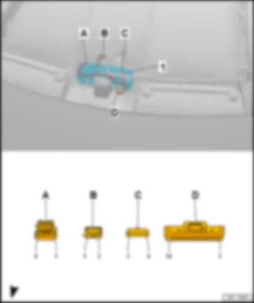
AUDI R8 2017 Fitting location, roof electronics control unit J528
In front roof module -WX3- .
1 - Roof electronics control unit -J528-
B - 3-pin connector -T3d- , black
q for garage door operating unit -E284-
D - 12-pin connector -T12g- , black
q for roof electronics control unit -J528-
-T12g- (A) Designation -T12g- (A) Designation 1 7 Automatic anti-dazzle interior mirror -Y7- 2 8 Terminal 30, from fuse carrier 4 -ST4- in fuse holder C -SC- 3 9 Onboard supply control unit -J519- 4 Terminal 15, from fuse carrier 1 -ST1- in fuse holder C -SC- 10 Terminal 31, to 689 earth point, at front, central in roof 5 11 Terminal 58s, to B732 connection 2 (58s) in main wiring harness 6 Airbag control unit -J234- 12 Terminal 30, from B485 connection 21 in main wiring harness
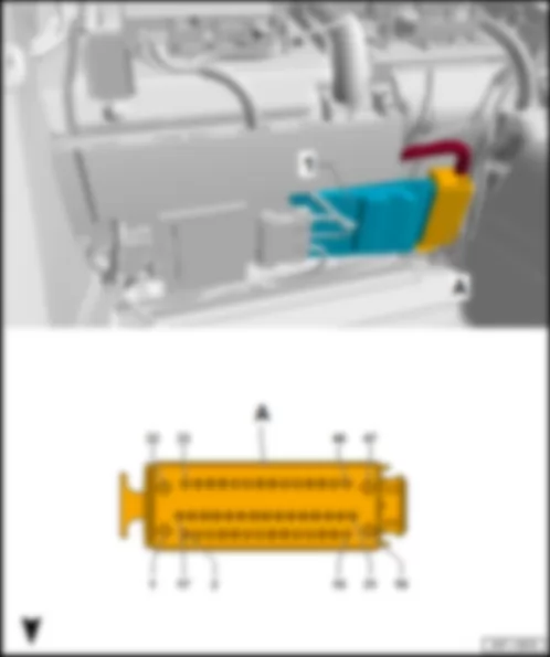
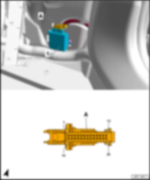
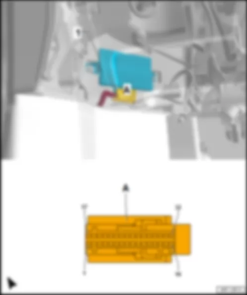
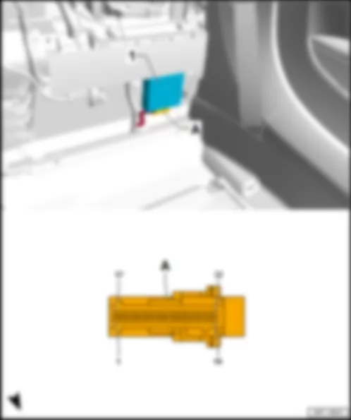
AUDI R8 2017 Fitting location, data bus diagnostic interface J533
In the footwell on the driver side on the top of the wheel housing behind the dash panel.
1 - Data bus diagnostic interface -J533-
Connector assignment, data bus diagnostic interface -J533-
-T32c- (A) Designation -T32c- (A) Designation 1 17 LIN bus, to B528 connection 1 (LIN bus) in main wiring harness 2 Extended CAN bus low, to B109 connection 1 (extended CAN bus low) in main wiring harness1) /2) 18 Extended CAN bus high, to B108 connection 1 (extended CAN bus high) in main wiring harness1) /2) 3 Diagnostic low CAN bus, to diagnostic connection -U31- 19 Diagnostic high CAN bus, to diagnostic connection -U31- 4 Comfort low CAN bus to B406 connection 1 (comfort low CAN bus) in main wiring harness 20 Comfort high CAN bus, to B397 connection 1 (comfort high CAN bus) in main wiring harness 5 Drive low CAN bus, to B391 connection 2 (drive low CAN bus) in main wiring harness 21 Drive high CAN bus to B384 connection 2 (drive high CAN bus) in main wiring harness 6 Dash panel insert CAN bus low, to B709 connection 1 (dash panel insert CAN bus low) in main wiring harness 22 Dash panel insert CAN bus high, to B708 connection 1 (dash panel insert CAN bus high) in main wiring harness 7 FlexRay bus, to ABS control unit -J104- 23 FlexRay bus, to ABS control unit -J104- 8 24 9 25 10 FlexRay bus, to control unit for sensor electronics -J849- 26 FlexRay bus, to control unit for sensor electronics -J849- 11 27 12 28 13 Terminal 31, to 639 earth point on left A-pillar 29 Terminal 31, to 639 earth point on left A-pillar 14 Terminal 15, from fuse carrier 1 -ST1- in fuse holder C -SC- 30 15 Running gear sensors CAN bus low, to B664 connection (running gear sensors CAN bus low) in main wiring harness 31 Running gear sensors CAN bus high, to B663 connection (running gear sensors CAN bus high) in main wiring harness 16 Terminal 30, from fuse carrier 3 -ST3- in fuse holder C -SC- 32
1) Models with main beam assist control unit -J844-
2) Models without main beam assist control unit -J844-
In the footwell on the front passenger side, at the bottom of the wheel housing under the carpet
1 - Data bus diagnostic interface -J533-
A - 32-pin connector -T32c- , black
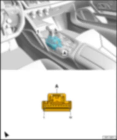
AUDI R8 2017 Fitting location, selector lever sensors control unit J587
In selector lever -E313- in centre console.
1 - Selector lever sensors control unit -J587-
q in selector lever -E313-
Connector assignment, selector lever sensors control unit -J587-
-T10d- (A) Designation -T10d- (A) Designation 1 Terminal 30, from fuse carrier 4 -ST4- in fuse holder C -SC- 6 2 7 3 Drive low CAN bus, to B391 connection 2 (drive low CAN bus) in main wiring harness 8 4 Drive high CAN bus to B384 connection 2 (drive high CAN bus) in main wiring harness 9 5 10 Terminal 31, to 687 earth point 1 on centre tunnel
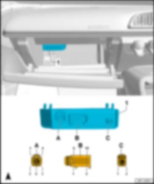
AUDI R8 2017 Fitting location, chip card reader control unit J676
At the top of the glove compartment.
1 - Chip card reader control unit -J676-
B - 10-pin connector -T10k- , black
Connector assignment, chip card reader control unit -J676-
-T10k- (A) Designation -T10k- (A) Designation 1 Traffic data aerial -R173- 6 Control unit 1 for information electronics -J794- 2 Traffic data aerial -R173- 7 Traffic data aerial -R173- 3 Traffic data aerial -R173- 8 Traffic data aerial -R173- 4 Traffic data aerial -R173- 9 Terminal 30, from fuse carrier 6 -ST6- in fuse holder C -SC- 5 10 Terminal 31, to 638 earth point on right A-pillar
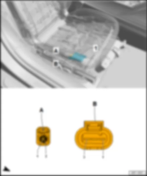
AUDI R8 2017 Fitting location, seat occupied recognition control unit J706
On front passenger side at the bottom.
1 - Seat occupied recognition control unit -J706-
q To sensor pad in front passenger seat
Connector assignment, seat occupied recognition control unit -J706-
-T3bi- (B) Designation 1 Terminal 15, from fuse carrier 1 -ST1- in fuse holder C -SC- 2 Airbag control unit -J234- 3 Terminal 31 to 471 earth connection 5 in seat adjustment wiring harness
AUDI R8 2017 Fitting location, control unit for electronic steering column lock J764
On top of the steering column.
1 - Control unit for electronic steering column lock -J764-
Connector assignment of control unit for electronic steering column lock -J764-
-T6s- (A) Designation 1 Convenience system central control unit -J393- 2 Onboard supply control unit -J519- 3 Terminal 31, to 664 earth point on left behind dash panel 4 Convenience system central control unit -J393- 5 LIN bus, to B698 connection 3 (LIN bus) in main wiring harness 6 Terminal 30, from fuse carrier 3 -ST3- in fuse holder C -SC-
AUDI R8 2017 Fitting location Reversing camera system control unit J772
Under the rear shelf at the bottom outer right on the rear wall.
1 - Reversing camera system control unit -J772-
B - 2-pin connector -T2bs- , green
q to control unit for information electronics 1 -J794-
Connector assignment, reversing camera system control unit -J772-
-T20a- (C) Designation -T20a- (C) Designation 1 11 Dash panel insert CAN bus low, to B709 connection 1 (dash panel insert CAN bus low) in main wiring harness 2 12 Dash panel insert CAN bus high, to B708 connection 1 (dash panel insert CAN bus high) in main wiring harness 3 13 4 14 5 15 6 16 7 17 8 18 9 Reversing camera -R189- 19 Reversing camera -R189- 10 Terminal 30, from fuse carrier 6 -ST6- in fuse holder C -SC- 20 Terminal 31, to 35 earth point under front passenger seat
AUDI R8 2017 Fitting location, active steering control unit J792
On the left on the steering column, behind the dash panel.
1 - Active steering control unit -J792-
B - 8-pin connector -T8n- , black
Connector assignment, active steering control unit -J792-
-T10i- (A) Designation -T8n- (B) Designation -T5f- (C) Designation 1 Active steering safety lock actuator -F437- 1 1 Active steering motor -V477- 2 Active steering safety lock actuator -F437- 2 Terminal 15, from fuse carrier 1 -ST1- in fuse holder C -SC- 2 Active steering motor -V477- 3 Running gear sensors CAN bus low, to B664 connection (running gear sensors CAN bus low) in main wiring harness 3 Signal from position sensor 4 3 Active steering motor -V477- 4 Running gear sensors CAN bus high, to B663 connection (running gear sensors CAN bus high) in main wiring harness 4 Signal from position sensor 3 4 Terminal 31, to 670 earth point 2 on left A-pillar 5 5 Signal from position sensor 2 5 Terminal 30, from fuse 3 (30) -S206- on cover of main fuse carrier 6 6 Signal from position sensor 1 7 7 Earth supply for position sensors 8 8 Positive supply for position sensors 9 10
AUDI R8 2017 Fitting location, control unit 1 for information electronics J794
Under the rear shelf in the centre of the rear wall.
1 - Control unit 1 for information electronics -J794-
B - C - 8-pin connector -T8h- , black
E - 12-pin connector -T12k- , green
G - 8-pin connector -T8g- , brown
J - 5-pin connector -T5v- , yellow
q to connection for external audio sources -R199-
L - 4-pin connector -T4z- , white
q AM/FM aerial connection from aerial amplifier -R24- for aerial -R11-
q FM2 aerial connection from aerial amplifier 2 -R111- for radio aerial 2 -R93-
Connector assignment, control unit 1 for information electronics -J794-
-T8h- (C) Designation -T12i- (D) Designation -T12k- (E) Designation 9 1 CAN bus, control unit 1 for information electronics, high, to E145 connection 1 (CAN bus, control unit 1 for information electronics, high) 1 Connection for external audio sources -R199- , AUX IN earth 10 Centre loudspeaker -R208-1) 2 Multimedia system operating unit -E380- 2 Connection for external audio sources -R199- , AUX IN right 11 3 Ring break diagnosis, to B444 connection 1 (diagnosis) in main wiring harness 3 Connection for external audio sources -R199- , USB earth 12 4 4 13 5 Chip card reader control unit -J676- /aerial amplifier for mobile telephone -R86- /telephone bracket -R126- 5 14 Centre loudspeaker -R208-1) 6 Dash panel insert CAN bus high, to A204 connection (dash panel insert CAN bus high) in dash panel wiring harness 6 17 Terminal 31, to 688 earth point 2 on centre tunnel 7 CAN bus, control unit 1 for information electronics, low, to E147 connection 1 (CAN bus, control unit 1 for information electronics, low) 7 Connection for external audio sources -R199- , AUX IN left 18 Terminal 30, from fuse carrier 6 -ST6- in fuse holder C -SC- 8 Multimedia system operating unit -E380- 8 Connection for external audio sources -R199- , screen earth 9 9 10 10 11 Telephone bracket -R126- 11 12 Dash panel insert CAN bus low, to A205 connection (dash panel insert CAN bus low) in dash panel wiring harness 12
1) Only models without digital sound package control unit -J525-
-T12h- (F) Designation -T8g- (G) Designation 1 Control unit for seat belt microphone -J886- 1 Front right treble loudspeaker -R22-1) 2 Control unit for seat belt microphone -J886- 2 Front right bass loudspeaker -R23-1) 3 3 Front left bass loudspeaker -R21-1) 4 4 Front left treble loudspeaker -R20-1) 5 5 Front right treble loudspeaker -R22-1) 6 Reversing camera system control unit -J772- 6 Front right bass loudspeaker -R23-1) 7 Control unit for seat belt microphone -J886- 7 Front left bass loudspeaker -R21-1) 8 Control unit for seat belt microphone -J886- 8 Front left treble loudspeaker -R20-1) 9 10 11 12 Reversing camera system control unit -J772-
1) Only models without digital sound package control unit -J525-
AUDI R8 2017 Fitting location, interface control unit for vehicle location system J843
In the footwell on the front passenger side above the onboard supply control unit -J519- .
1 - Interface control unit for vehicle location system -J843-
A - 12-pin connector -T12-
12-pin connector -T12b- , brown
C - 20-pin connector -T20-
-T12b- (B) Designation -T12b- (B) Designation 1 7 Comfort high CAN bus, to B398 connection 2 (comfort high CAN bus) in main wiring harness 2 8 Comfort low CAN bus to B407 connection 2 (comfort low CAN bus) in main wiring harness 3 Terminal 30, from fuse carrier 5 -ST5- in fuse holder C -SC- 9 4 10 5 11 6 Terminal 31, to 751 earth point 2 on right A-pillar 12
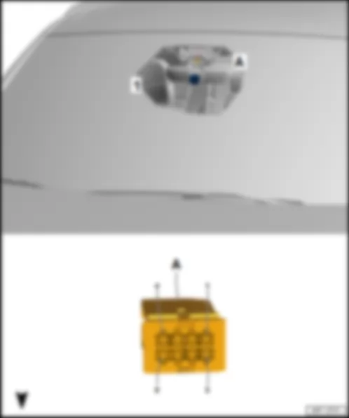
AUDI R8 2017 Fitting location Main beam assist control unit J844
1 - Main beam assist control unit -J844-
Connector assignment of main beam assist control unit -J844-
-T8b- (A) Designation -T8b- (A) Designation 1 Terminal 15, from fuse carrier 1 -ST1- in fuse holder C -SC- 5 Mirror dimming signal line, to B428 connection 2 (mirror signal) in main wiring harness 2 Terminal 31, to 689 earth point, at front, central in roof 6 Roof electronics control unit -J528- 3 Extended high CAN bus, to B108 connection 1 (extended high CAN bus) in main wiring harness 7 4 Mirror dimming signal line, to B427 connection 1 (mirror signal) in main wiring harness 8 Extended CAN bus low, from B109 connection 1 (extended CAN bus low) in main wiring harness
AUDI R8 2017 Fitting location, control unit for sensor electronics J849
Under the centre console at the front on the centre tunnel behind the airbag control unit -J234- .
1 - Control unit for sensor electronics -J849-
Connector assignment, control unit for sensor electronics -J849-
-T50a- (A) Designation -T50a- (A) Designation 1 26 Terminal 31, to 687 earth point 1 on centre tunnel 2 27 3 Terminal 15, from fuse carrier 1 -ST1- in fuse holder C -SC- 28 4 29 5 30 6 31 7 32 8 33 9 34 10 35 11 36 12 37 13 38 14 39 15 40 16 41 17 42 18 43 19 FlexRay bus, from data bus diagnostic interface -J533- 44 20 FlexRay bus, from data bus diagnostic interface -J533- 45 21 46 22 47 23 48 24 49 25 50
AUDI R8 2017 Fitting location, control unit for seat belt microphone J886
Under the rear shelf at the bottom left on the rear wall.
1 - Control unit for seat belt microphone -J886-
Connector assignment, control unit for seat belt microphone -J886-
-T32g- (A) Designation -T32g- (A) Designation 1 Telephone microphone -R38- in microphone unit in front roof module -R164- 17 Telephone microphone -R38- in microphone unit in front roof module -R164- 2 Microphone 1 on driver side -R224- 18 Microphone 1 on front passenger side -R227- 3 Microphone 2 on driver side -R225- 19 Microphone 2 on front passenger side -R228- 4 Microphone 3 on driver side -R226- 20 Microphone 3 on front passenger side -R229- 5 Driver side microphone shielding 21 Front passenger side microphone shielding 6 Driver side microphone positive supply 22 Front passenger side microphone positive supply 7 Driver side microphone earth supply 23 Front passenger side microphone earth supply 8 Terminal 31, to 688 earth point 2 on centre tunnel 24 9 Control unit 1 for information electronics -J794- 25 Control unit 1 for information electronics -J794- 10 Control unit 1 for information electronics -J794- 26 Control unit 1 for information electronics -J794- 11 27 12 28 13 29 14 Terminal 30, from fuse carrier 6 -ST6- in fuse holder C -SC- 30 15 31 16 Dash panel insert CAN bus high, to B708 connection 1 (dash panel insert CAN bus high) in main wiring harness 32 Dash panel insert CAN bus low, to B709 connection 1 (dash panel insert CAN bus low) in main wiring harness
AUDI R8 2017 Fitting location TV tuner R78
Under the rear shelf at the outer right on the rear wall.
B - 4-pin connector -T4q- , green
q from aerial amplifier -R24- for aerial 2 for TV -R56- and aerial amplifier 3 -R112- for aerial 3 for TV -R57-
D - 12-pin connector -T12f- , black
-T12f- (D) Designation -T12f- (D) Designation 1 Terminal 30, from fuse carrier 2 -ST2- in fuse holder D -SD- 7 2 Terminal 31, to 688 earth point 2 on centre tunnel 8 3 Ring break diagnosis, to B444 connection 1 (diagnosis) in main wiring harness 9 4 10 5 11 6 12
AUDI R8 2017 Fitting location, aerial amplifier for mobile telephone R86
Under the rear shelf at the bottom of the rear wall on the right next to the electronically controlled damping control unit -J250- .
1 - Aerial amplifier for mobile telephone -R86-
B - 4-pin connector -T4p- , black
Connector assignment, aerial amplifier for mobile telephone -R86-
-T4p- (B) Designation 1 Terminal 30, from fuse carrier 2 -ST2- in fuse holder FD -SD- 2 Terminal 31, to 35 earth point under front passenger seat 3 Control unit 1 for information electronics -J794- 4
AUDI R8 2017 Overview of fuse carrier Relay and fuse carrier 2 -SR2- with fuse holder B -SB-
t Fuse for engine electronics -S282-
q Fitting location and assignment
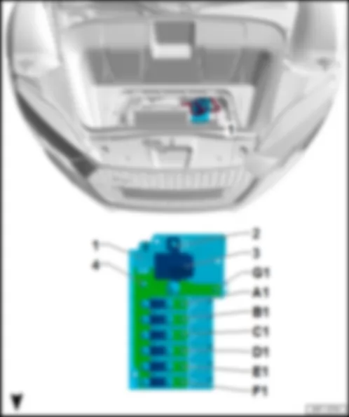
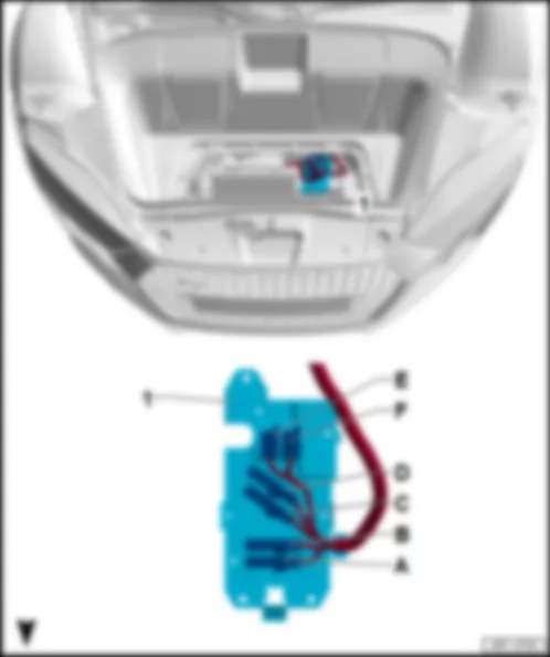
AUDI R8 2017 Fitting location, main fuse carrier
The main fuse carrier is located on the left next to the battery -A- in the luggage compartment.
2 - Terminal 30 connection to starter -B-
3 - Battery isolation igniter -N253-
4 - Terminal 30 from positive terminal of battery -A-
A1 - Fuse 1 -S131-, 150 A
t Terminal 15 voltage supply relay -J329-
t Fuse carrier 2 -ST2- in relay and fuse carrier 3 -SR3-
t Fuse carrier 3 -ST3- in relay and fuse carrier 3 -SR3-
t Fuse carrier 4 -ST4- in relay and fuse carrier 3 -SR3-
t Fuse carrier 6 -ST6- in relay and fuse carrier 3 -SR3-
B1 - Fuse 2 -S132-, 200 A
t Radiator fan single fuse -S42-
t Radiator fan fuse for 2nd speed -S104-
q for ABS control unit -J104-
D1 - Fuse 4 -S134-, 150 A
t Engine component current supply relay -J757-
t Fuse carrier 1 -ST1- in relay and fuse carrier 2 -SR2-
t Fuse -SB5-/-SB7- on fuse carrier 2 -ST2- in relay and fuse carrier 2 -SR2-
E1 - Fuse 5 -S138-, 125 A
t Heated rear window relay -J9-
t Fuse carrier 1 -ST1- in relay and fuse carrier 4 -SR4-
t Fuse carrier 2 -ST2- in relay and fuse carrier 4 -SR4-
F1 - Fuse 6 -S139-, 125 A
q for power steering control unit -J500-
G1 - Terminal 30 to battery monitor control unit -J367-
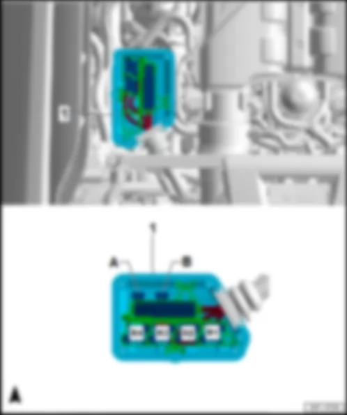
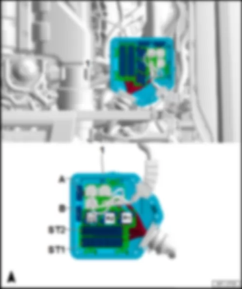
AUDI R8 2017 Fitting location, fuse holder on cover for main fuse carrier
The fuse holder on the cover for the main fuse carrier is located on the left next to the battery -A- in the luggage compartment.
1 - Fuse holder on cover for main fuse carrier
A - Radiator fan single fuse -S42-, green, 40 A
q for radiator fan control unit -J293-
B - Radiator fan fuse for 2nd speed -S104-, red, 40 A
q for radiator fan control unit 2 -J671-
C - Fuse 2 (30) -S205-, black, 80 A
t Fuse carrier 5 -ST5- in fuse holder C -SC-
t Driver seat adjustment thermal fuse 1 -S44-
t Front passenger seat adjustment thermal fuse 1 -S46-
E - Fuse 1 (30) -S204-, black, 30 A
q for all-wheel drive control unit -J492-
F - Fuse 3 (30) -S206-, brown, 40 A
q for active steering control unit -J792-
AUDI R8 2017 Fitting location, relay and fuse carrier 1 SR1 with fuse holder A SA
The relay and fuse carrier 1 -SR1- is located in the electronics box on the left in the engine compartment.
1 - Relay and fuse carrier 1 -SR1- with fuse holder A -SA-
AUDI R8 2017 Fuse assignment on fuse holder A SA
No. Current Flow Diagram designation Nominal value Function/component Terminal 1 - not assigned - 2 - not assigned - 3 - not assigned - 4 - not assigned - 5 - Fuse 5 on fuse holder A -SA5- 7.5 A - Intake air temperature sensor -G42-/mass air flow sensor -G70- 87 6 - Fuse 6 on fuse holder A -SA6- 10 A - Camshaft adjustment valve 1 -N205- 87 7 - Fuse 7 on fuse holder A -SA7- 15 A - Lambda probe heater -Z19- 87 8 - Fuse 8 on fuse holder A -SA8- 7.5 A - Secondary air pump relay -J299- 87 9 - Fuse 9 on fuse holder A -SA9- 20 A - Engine control unit -J623- 87 10 - Fuse 10 on fuse holder A -SA10- 15 A - Lambda probe 1 heater after catalytic converter -Z29- 87 11 - Fuse 11 on fuse holder A -SA11- 5 A - Oil level and oil temperature sender -G266- 87 12 - Fuse 12 on fuse holder A -SA12- 5 A - Radiator fan control unit -J293- 87
AUDI R8 2017 Fitting location, relay and fuse carrier 2 SR2 with fuse holder B SB
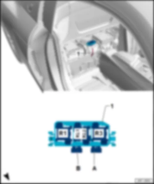
The relay and fuse carrier 2 -SR2- is located in the electronics box on the right in the engine compartment.
1 - Relay and fuse carrier 2 -SR2- with fuse holder B -SB-
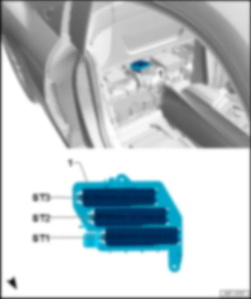
ST1 - Fuse carrier 1 -ST1-, black
ST2 - Fuse carrier 2 -ST2-, black
B - Engine electronics fuse -S282-, 40 A
AUDI R8 2017 Fuse assignment on fuse holder B SB
No. Current Flow Diagram designation Nominal value Function/component Terminal 1 - Fuse 1 on fuse holder B -SB1- 50 A - Secondary air pump relay -J299- 30 2 - Fuse 2 on fuse holder B -SB2- 50 A - Secondary air pump 2 relay -J545- 30 3 - not assigned - 4 - not assigned - 5 - Fuse 5 on fuse holder B -SB5- 5 A - Engine control unit -J623- 50 6 - not assigned -
No. Current Flow Diagram designation Nominal value Function/component Terminal 1 - Fuse 1 on fuse holder B -SB1- 5 A - Mechatronic unit for dual clutch gearbox -J743- 15 2 - Fuse 2 on fuse holder B -SB2- 5 A - Automatic gearbox control unit 2 -J1006- 15 3 - Fuse 3 on fuse holder B -SB3- 5 A - Engine control unit -J623- 15 4 - not assigned - 5 - Fuse 5 on fuse holder B -SB5- 15 A - Mechatronic unit for dual clutch gearbox -J743- 30 6 - not assigned - 7 - Fuse 7 on fuse holder B -SB7- 5 A - Engine control unit -J623- 30 8 - not assigned - 9 - Fuse 9 on fuse holder B -SB9- 10 A - Fuel metering valve -N290- 87 10 - Fuse 10 on fuse holder B -SB10- 7.5 A - Injection valve 2 for cylinder 6 -N537- 87 11 - Fuse 11 on fuse holder B -SB11- 7.5 A - Injection valve 2 for cylinder 1 -N532- 87 12 - Fuse 12 on fuse holder B -SB12- 30 A - Ignition coil 1 with output stage -N70- 87
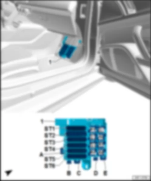
AUDI R8 2017 Fitting location, relay and fuse carrier 3 SR3 with fuse holder C SC
The relay and fuse carrier 3 -SR3- is located in the footwell on the front passenger side.
1 - Relay and fuse carrier 3 -SR3- with fuse holder C -SC-
ST1 - Fuse carrier 1 -ST1-, black
ST2 - Fuse carrier 2 -ST2-, black
ST3 - Fuse carrier 3 -ST3-, black
ST4 - Fuse carrier 4 -ST4-, red
ST5 - Fuse carrier 5 -ST5-, brown
ST6 - Fuse carrier 6 -ST6-, black
C - Driver seat adjustment thermal fuse 1 -S44-, 15 A
E - Front passenger seat adjustment thermal fuse 1 -S46-, 15 A
AUDI R8 2017 Fuse assignment, fuse holder C SC
No. Current Flow Diagram designation Nominal value Function/component Terminal 1 - Fuse 1 on fuse holder C -SC1- 5 A - Steering column electronics control unit -J527- 15 2 - Fuse 2 on fuse holder C -SC2- 5 A - ASR/ESP button -E256- 15 3 - Fuse 3 on fuse holder C -SC3- 5 A - Control unit for sensor electronics -J849- 15 4 - Fuse 4 on fuse holder C -SC4- 5 A - Active steering control unit -J792- 15 5 - Fuse 5 on fuse holder C -SC5- 10 A - Garage door operating unit -E284- 15 6 - Fuse 6 on fuse holder C -SC6- 5 A - Headlight range control unit -J431- 15 7 - Fuse 7 on fuse holder C -SC7- 5 A - Data bus diagnostic interface -J533- 15 8 - Fuse 8 on fuse holder C -SC8- 5 A - ABS control unit -J104- 15 9 - Fuse 9 on fuse holder C -SC9- 5 A - Airbag control unit -J234- 15 10 - Fuse 10 on fuse holder C -SC10- 5 A - Air quality sensor -G238-/humidity sender in fresh air intake duct -G657- 15 11 - Fuse 11 on fuse holder C -SC11- 15 A - Front left headlight -MX1- 15 12 - not assigned - 13 - Fuse 13 on fuse holder C -SC13- 15 A - Front right headlight -MX2- 15 14 - Fuse 14 on fuse holder C -SC14- 5 A - Automatic anti-dazzle interior mirror -Y7- 15 15 - Fuse 15 on fuse holder C -SC15- 40 A - Starter relay 1 -J906- 15 16 - Fuse 16 on fuse holder C -SC16- 30 A - Fuse carrier 2 -ST2- in fuse holder B -SB- 15
No. Current Flow Diagram designation Nominal value Function/component Terminal 1 - not assigned - 2 - not assigned - 3 - Fuse 3 on fuse holder C -SC3- 40 A - Fresh air blower control unit -J126- 30 4 - Fuse 4 on fuse holder C -SC4- 40 A - Onboard supply control unit -J519- 30 5 - not assigned - 6 - not assigned -
No. Current Flow Diagram designation Nominal value Function/component Terminal 1 - Fuse 1 on fuse holder C -SC1- 10 A - Diagnostic connection -U31- 30 2 - Fuse 2 on fuse holder C -SC2- 5 A - Electromechanical parking brake warning lamp -K213- in electromechanical parking brake button -E538- 30 3 - Fuse 3 on fuse holder C -SC3- 5 A - Data bus diagnostic interface -J533- 30 4 - Fuse 4 on fuse holder C -SC4- 15 A - Brake servo relay -J569-/vacuum pump for brakes -V192- 30 5 - not assigned - 6 - Fuse 6 on fuse holder C -SC6- 20 A - Relay for power sockets -J807- 30 7 - Fuse 7 on fuse holder C -SC7- 5 A - Control unit in dash panel insert -J285- 30 8 - Fuse 8 on fuse holder C -SC8- 5 A - Immobiliser reader coil -D2- 30 9 - Fuse 9 on fuse holder C -SC9- 5 A - Control unit for electronic steering column lock -J764- 30 10 - not assigned - 11 - not assigned - 12 - not assigned -
No. Current Flow Diagram designation Nominal value Function/component Terminal 1 - not assigned - 2 - not assigned - 3 - Fuse 3 on fuse holder C -SC3- 5 A - Control unit for sensor electronics -J849- 30 4 - Fuse 4 on fuse holder C -SC4- 5 A - Terminal 15 voltage supply relay -J329- 30 5 - Fuse 5 on fuse holder C -SC5- 10 A - Selector lever -E313- 30 6 - not assigned - 7 - Fuse 7 on fuse holder C -SC7- 5 A - Roof electronics control unit -J528- 30 8 - Fuse 8 on fuse holder C -SC8- 30 A - Wiper motor control unit -J400- 30 9 - Fuse 9 on fuse holder C -SC9- 30 A - Front passenger side wiper motor control unit -J584- 30 10 - Fuse 10 on fuse holder C -SC10- 15 A - Horn relay -J413- 30 11 - Fuse 11 on fuse holder C -SC11- 5 A - Steering column electronics control unit -J527- 30 12 - Fuse 12 on fuse holder C -SC12- 5 A - Light switch -E1- 30
No. Current Flow Diagram designation Nominal value Function/component Terminal 1 - Fuse 1 on fuse holder C -SC1- 10 A - ABS control unit -J104- 30 2 - Fuse 2 on fuse holder C -SC2- 20 A - ABS control unit -J104- 30 3 - Fuse 3 on fuse holder C -SC3- 10 A - Operating and display unit for front air conditioning system -E87- 30 4 - Fuse 4 on fuse holder C -SC4- 5 A - Interface control unit for vehicle location system -J843- 30 5 - Fuse 5 on fuse holder C -SC5- 30 A - Driver door control unit -J386- 30 6 - Fuse 6 on fuse holder C -SC6- 30 A - Front passenger door control unit -J387- 30 7 - Fuse 7 on fuse holder C -SC7- 30 A - Onboard supply control unit -J519- 30 8 - Fuse 8 on fuse holder C -SC8- 30 A - Onboard supply control unit -J519- 30 9 - Fuse 9 on fuse holder C -SC9- 30 A - Onboard supply control unit -J519- 30 10 - Fuse 10 on fuse holder C -SC10- 5 A - Anti-theft alarm sensor -G578- 30 11 - Fuse 11 on fuse holder C -SC11- 20 A - Onboard supply control unit -J519- 30 12 - Fuse 12 on fuse holder C -SC12- 5 A - Humidity sender -G355-/rain and light sensor -G397- 30
No. Current Flow Diagram designation Nominal value Function/component Terminal 1 - not assigned - 2 - not assigned - 3 - not assigned - 4 - not assigned - 5 - not assigned - 6 - not assigned - 7 - Fuse 7 on fuse holder C -SC7- 5 A - Multimedia system operating unit -E380- 30 8 - Fuse 8 on fuse holder C -SC8- 5 A1) /20 A2) - Control unit 1 for information electronics -J794- 30 9 - Fuse 9 on fuse holder C -SC9- 5 A3) /7.5 A4) - Chip card reader control unit -J676- 30 10 - Fuse 10 on fuse holder C -SC10- 30 A - Digital sound package control unit -J525- 30 11 - Fuse 11 on fuse holder C -SC11- 7.5 A - Reversing camera system control unit -J772- 30 12 - Fuse 12 on fuse holder C -SC12- 5 A - Connection for external audio sources -R199- 30
1) Only models with digital sound package control unit -J525-
2) Only models without digital sound package control unit -J525-
3) Only models without chip card reader control unit -J676-
4) Only models with chip card reader control unit -J676-
AUDI R8 2017 Fitting location, relay and fuse carrier 4 SR4 with fuse holder D SD
The relay and fuse carrier 4 -SR4- is located under the rear shelf on the rear wall on the right next to the control unit 1 for information electronics -J794-.
1 - Relay and fuse carrier 4 -SR4- with fuse holder D -SD-, part 1
ST1 - Fuse carrier 1 -ST1-, black
ST2 - Fuse carrier 2 -ST2-, brown
ST3 - Fuse carrier 3 -ST3-, red
1 - Relay and fuse carrier 4 -SR4-, part 2
AUDI R8 2017 Fuse assignment on fuse holder D SD
No. Current Flow Diagram designation Nominal value Function/component Terminal 1 - not assigned - 2 - not assigned - 3 - Fuse 3 on fuse holder D -SD3- 5 A - Brake light switch -F- 87 4 - not assigned - 5 - Fuse 5 on fuse holder D -SD5- 30 A - Fuel pump control unit -J538- 87 6 - not assigned - 7 - Fuse 7 on fuse holder D -SD7- 30 A - Control unit for electromechanical parking brake -J540- 30 8 - Fuse 8 on fuse holder D -SD8- 30 A - Control unit for electromechanical parking brake -J540- 30 9 - Fuse 9 on fuse holder D -SD9- 20 A - Electronically controlled damping control unit -J250- 30 10 - Fuse 10 on fuse holder D -SD10- 5 A - Tyre Pressure Monitoring System control unit -J502- 30 11 - not assigned - 12 - not assigned -
No. Current Flow Diagram designation Nominal value Function/component Terminal 1 - Fuse 1 on fuse holder D -SD1- 5 A - Electronically controlled damping control unit -J250- 15 2 - Fuse 2 on fuse holder D -SD2- 10 A - Rear lid release switch -E165- 15 3 - Fuse 3 on fuse holder D -SD3- 5 A - Control unit for electromechanical parking brake -J540- 15 4 - Fuse 4 on fuse holder D -SD4- 5 A - Aerial amplifier for mobile telephone -R86- 30 5 - Fuse 5 on fuse holder D -SD5- 5 A - Control unit for fuel tank leak detection -J909- 30 6 - Fuse 6 on fuse holder D -SD6- 30 A - Convenience system central control unit -J393- 30 7 - Fuse 7 on fuse holder D -SD7- 20 A - Adjustable rear spoiler control unit -J223- 30 8 - Fuse 8 on fuse holder D -SD8- 30 A - Convenience system central control unit -J393- 30 9 - not assigned - 10 - Fuse 10 on fuse holder D -SD10- 20 A - Convenience system central control unit -J393- 30 11 - Fuse 11 on fuse holder D -SD11- 15 A - Automatic gearbox control unit 2 -J1006- 30 12 - Fuse 12 on fuse holder D -SD12- 7.5 A - TV tuner -R78- 30
No. Current Flow Diagram designation Nominal value Function/component Terminal 1 - Fuse 1 on fuse holder D -SD1- 15 A - Heated partition glass -Z106- 87 2 - Fuse 2 on fuse holder D -SD2- 30 A - Heated rear window -Z1- 87 3 - not assigned - 4 - not assigned - 5 - not assigned - 6 - not assigned - 7 - not assigned - 8 - not assigned - 9 - not assigned - 10 - not assigned - 11 - not assigned - 12 - not assigned -
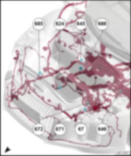
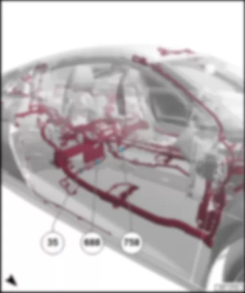
AUDI R8 2017 Earth points in front part
Earth point, on left of front cross member
Earth point next to starter battery
q Specified torque: 20 Nm
Earth point 1, on bulkhead
Earth point 2, on bulkhead
Earth point 1, on front left longitudinal member
Earth point 2, on front left longitudinal member
q Specified torque: 20 Nm
Earth point 1 on front longitudinal member, right
Earth point 2 on front longitudinal member, right
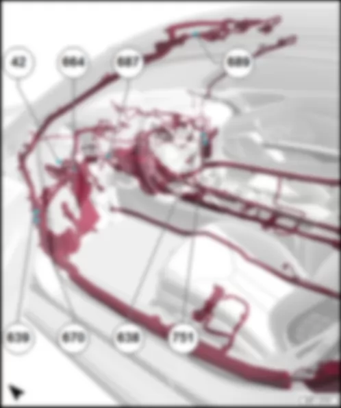
Earth point next to steering column
Earth point on right A-pillar
Earth point on left A-pillar
Earth point, on left behind dash panel
Earth point 2 on left A-pillar
Earth point 1 on centre tunnel
Earth point, at front, central in roof
Earth point 2 on right A-pillar
Earth point, under front passenger seat
Earth point 2 on centre tunnel
Earth point 3 on centre tunnel
Earth point in engine compartment, left
Earth point, on right in engine compartment
Earth point on gearbox
q Specified torque: 20 Nm
Earth point 1, on cylinder head cover
Earth point 2, on cylinder head cover
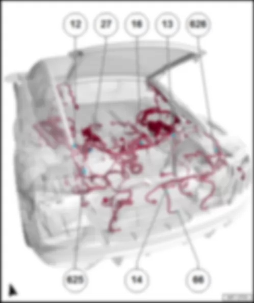
Earth point, on rear of right longitudinal member
q Specified torque: 20 Nm
Earth point for left tail light
Earth point for right tail light
Can't find your car? Check -> DiagnostData.com !

