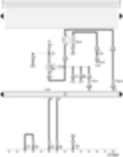
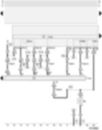
Wiring Diagram AUDI A4 2000 - Fuses - brake light switch - ABS with EDL control unit

| F | Brake light switch |
| J104 | ABS with EDL control unit |
| S13 | Fuse in fuse box/relay plate |
| S241 | Fuse in fuse box |
| S242 | Fuse in fuse box |
| T10b | 10-pin connector, orange, left connector point, A pillar |
| T10ap | 10-pin connector, grey, right connector point, A pillar |
| T10ar | 10-pin connector, orange, connector point, electronics box, plenum chamber |
| A18 | Connection (54), in dash panel wiring harness |
| A32 | Positive (+) connection (30), in dash panel wiring harness |
| A106 | Connection -2- (86s), in dash panel wiring harness |
| * | Only models with diesel engines |
| ** | Only models with petrol engines, without electronic throttle |
| *** | Only models with petrol engines, with electronic throttle |
| **** | See applicable engine version |
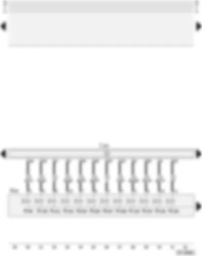
Wiring Diagram AUDI A4 2000 - Fuses - ABS with EDL control unit - traction control system switch
| D | Ignition/starter switch |
| E132 | Traction control system switch |
| J104 | ABS with EDL control unit |
| J218 | Combi-processor in dash panel insert |
| S7 | Fuse in fuse box/relay plate |
| T10b | 10-pin connector, orange, left connector point, A pillar |
| T10ap | 10-pin connector, grey, right connector point, A pillar |
| T32 | 32-pin connector, blue, on dash panel insert |
| 44 | Earth point, lower part of left A pillar |
| 100 | Earth connection -1-, in ABS wiring harness |
| 135 | Earth connection -2-, in dash panel wiring harness |
| A2 | Positive (+) connection (15), in dash panel wiring harness |
| A19 | Connection (58d), in dash panel wiring harness |
| A104 | Positive (+) connection -2- (15), in dash panel wiring harness |
| * | Only models with petrol engines, without electronic throttle |
| ** | Only models with petrol engines, with electronic throttle |
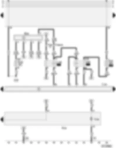
Wiring Diagram AUDI A4 2000 - ABS hydraulic unit - ABS with EDL control unit
| J104 | ABS with EDL control unit |
| N55 | ABS hydraulic unit |
| N99 | ABS inlet valve, front right |
| N100 | ABS outlet valve, front right |
| N101 | ABS inlet valve, front left |
| N102 | ABS outlet valve, front left |
| N133 | ABS inlet valve, rear right |
| N134 | ABS inlet valve, rear left |
| N135 | ABS outlet valve, rear right |
| N136 | ABS outlet valve, rear left |
| N225 | Electronic stability program switch valve -1- |
| N226 | Electronic stability program switch valve -2- |
| N227 | Electronic stability program high pressure valve -1- |
| N228 | Electronic stability program high pressure valve -2- |
Wiring Diagram AUDI A4 2000 - Fuses - steering angle sender - ABS relay - ABS with EDL control unit
| G85 | Steering angle sender |
| J104 | ABS with EDL control unit |
| J106 | Relay for ABS solenoid valves |
| J185 | ABS hydraulic pump relay |
| N55 | ABS hydraulic unit |
| S16 | Fuse in fuse box/relay plate |
| S53 | ABS hydraulic pump fuse |
| T10b | 10-pin connector, orange, left connector point, A pillar |
| T10ap | 10-pin connector, grey, right connector point, A pillar |
| V39 | ABS return flow pump |
| 44 | Earth point, lower part of left A pillar |
| 135 | Earth connection -2-, in dash panel wiring harness |
| A40 | Positive (+) connection -1- (30), in dash panel wiring harness |
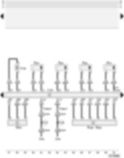
Wiring Diagram AUDI A4 2000 - Pressure sensor - speed sensors - yaw rate sender - ABS with EDL control unit
| G44 | Rear right speed sensor |
| G45 | Front right speed sensor |
| G46 | Rear left speed sensor |
| G47 | Front left speed sensor |
| G200 | Lateral acceleration sender |
| G201 | Brake pressure sender -1- |
| G202 | Yaw rate sender |
| J104 | ABS with EDL control unit |
| J402 | Operating electronics control unit, navigation |
| T10ap | 10-pin connector, grey, right connector point, A pillar |
| V156 | Electronic stability program hydraulic pump |
| A127 | Connection (rear left speed sensor), in dash panel wiring harness |
| A128 | Connection (rear right speed sensor), in dash panel wiring harness |
| * | Only models with quattro four-wheel drive |
| ** | Does not apply to models with quattro four-wheel drive |
| *** | Only models with radio navigation system |
Wiring Diagram AUDI A4 2000 - ABS with EDL control unit - combi-processor in dash panel insert
| F9 | Handbrake warning switch |
| J104 | ABS with EDL control unit |
| J218 | Combi-processor in dash panel insert |
| K7 | Dual circuit brake/handbrake warning lamp |
| K47 | ABS warning lamp |
| K86 | Traction control system warning lamp |
| T10b | 10-pin connector, orange, left connector point, A pillar |
| T10ap | 10-pin connector, grey, right connector point, A pillar |
| T16 | 16-pin connector, diagnostic connector |
| T32 | 32-pin connector, blue, on dash panel insert |
| T32a | 32-pin connector, green, on dash panel insert |
| 81 | Earth connection -1-, in dash panel wiring harness |
| A24 | Connection (brake system monitoring), in dash panel wiring harness |
| A76 | Connection (diagnosis wire K), in dash panel wiring harness |
| A91 | Connection (signal for dash panel insert), in dash panel wiring harness |
| A121 | Connection (high bus), in dash panel wiring harness |
| A122 | Connection (low bus), in dash panel wiring harness |
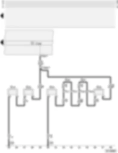
Wiring Diagram AUDI A4 2000 - Brake lining/pad wear senders
| G34 | Brake lining/pad wear sender, front left |
| G35 | Brake lining/pad wear sender, front right |
| G36 | Brake lining/pad wear sender, rear left |
| G37 | Brake lining/pad wear sender, rear right |
| J218 | Combi-processor in dash panel insert |
| T2 | 2-pin connector, red, rear right |
| T2a | 2-pin connector, red, rear left |
| T10ap | 10-pin connector, grey, right connector point, A pillar |
| T32a | 32-pin connector, green, on dash panel insert |
| 100 | Earth connection -1-, in ABS wiring harness |
| * | Does not apply to RS4 models |
| ** | Applies to RS4 models only |
Can't find your car? Check -> DiagnostData.com!

