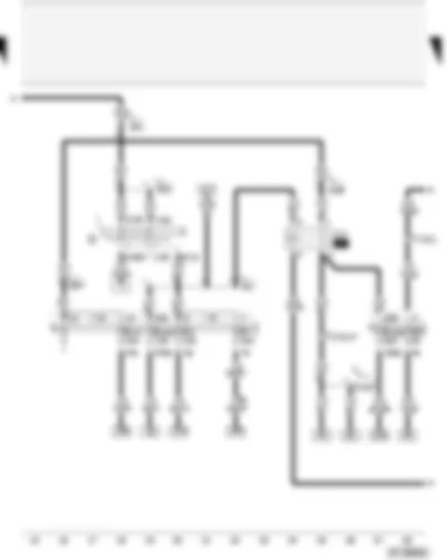
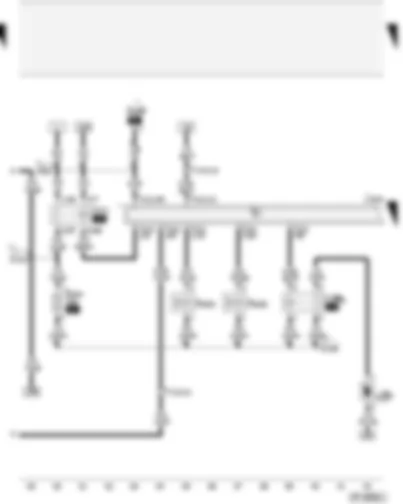
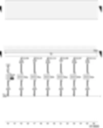
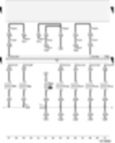
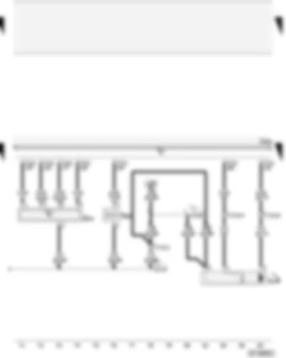
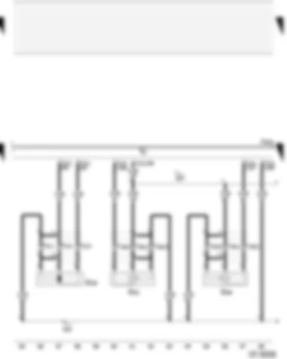
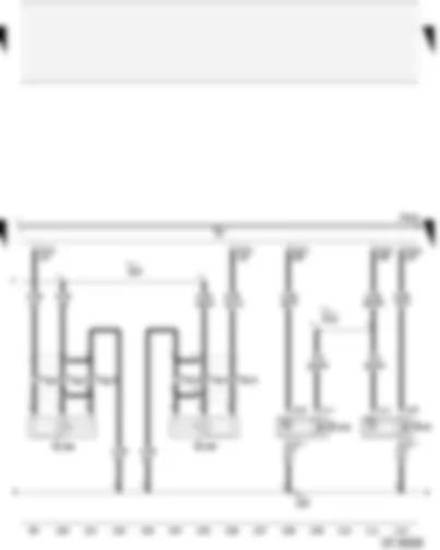
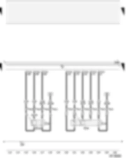
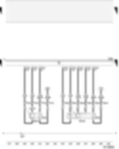
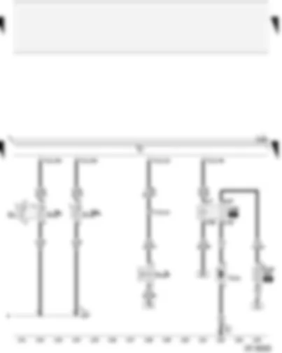
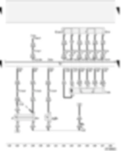
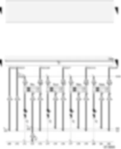
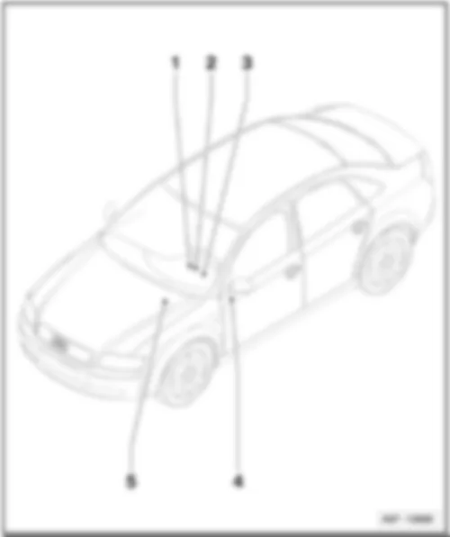
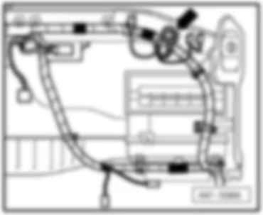
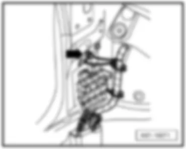
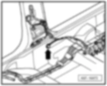
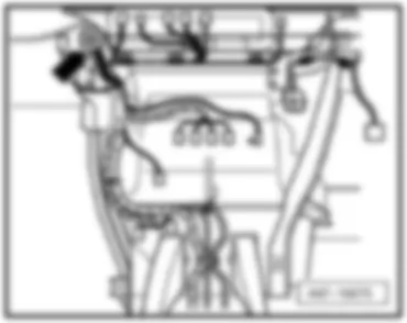
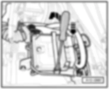
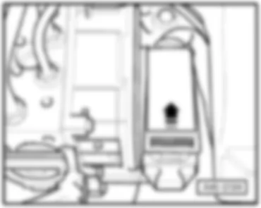
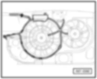
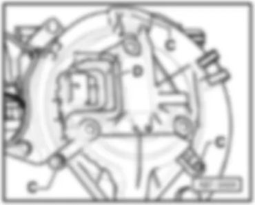
AUDI A4 2006 – 4.2 l – Fuel injection engine (253 kW – Motronic – 8 cylinder), engine code BHF . Wiring diagrams, Pin Connector, Location – Wiring diagrams for cars
AUDI A4 2006 – 4.2 l – Fuel injection engine (253 kW – Motronic – 8 cylinder), engine code BHF . Wiring diagrams, Pin Connector, Location
Wiring Diagram AUDI A4 2006 - Battery - starter - alternator A Battery B Starter C Alternator C1 Voltage regulator J207 Starter inhibitor relay J434 Starter inhibitor relay, clutch pedal switch S88 Strip fuse T4x 4-pin connector, black, near to the battery T17j 17-pin connector, brown, coupling station on electronics box, plenum chamber 500 Screw connection 1 (30), on relay plate * for models with manual gearbox only ** for models with automatic gearbox only (AG6), ⇒ applicable Current Flow Diagram: automatic gearbox *** for models with US equipment only and manual gearbox, ⇒ applicable Current Flow Diagram starter inhibitor relay, clutch pedal switch
Wiring Diagram AUDI A4 2006 - Ignition/starter switch - fuel pump relay - fuses D Ignition/starter switch J17 Fuel pump relay S4 Fuse in relay plate fuse holder S5 Fuse in relay plate fuse holder S7 Fuse in relay plate fuse holder S14 Fuse in relay plate fuse holder S228 Fuse in fuse holder S243 Fuse in fuse holder T17d 17-pin connector, red, coupling station on electronics box, plenum chamber T17j 17-pin connector, brown, coupling station on electronics box, plenum chamber 501 Screw connection 2 (30), on relay plate A2 Positive connection (15), in dash panel wiring harness A32 Positive connection (30), in dash panel wiring harness A57 Positive connection 3 (30), in dash panel wiring harness A98 Positive connection 4 (30), in dash panel wiring harness D103 Connection 3, in engine compartment wiring harness * applicable from model year 2006
Wiring Diagram AUDI A4 2006 - Engine control unit - Motronic current supply relay - inlet camshaft control valve 1 - continued coolant circulation pump J151 Continued coolant circulation relay J271 Motronic current supply relay J623 Engine control unit N205 Inlet camshaft control valve 1 N208 Inlet camshaft control valve 2 S286 Automatic gearbox fuse, run-on S344 Engine electronics fuse 2 T17d 17-pin connector, red, coupling station on electronics box, plenum chamber T17j 17-pin connector, brown, coupling station on electronics box, plenum chamber T121 121-pin connector, black V51 Continued coolant circulation pump D50 Positive connection (30), in engine compartment wiring harness D101 Connection 1, in engine compartment wiring harness D106 Connection 4, in engine compartment wiring harness * for models with automatic gearbox (AG6) only ** for countries with hot climate only
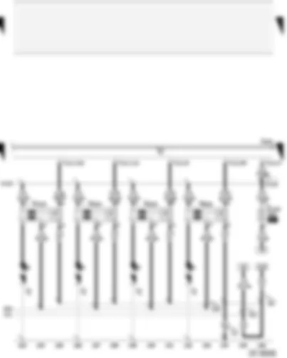
Wiring Diagram AUDI A4 2006 - Engine control unit - injectors J623 Engine control unit N30 Injector, cylinder 1 N31 Injector, cylinder 2 N32 Injector, cylinder 3 N33 Injector, cylinder 4 N83 Injector, cylinder 5 N84 Injector, cylinder 6 S116 Injector fuse T121 121-pin connector, black D95 Connection (injectors), in engine compartment wiring harness
Wiring Diagram AUDI A4 2006 - Engine control unit - injectors - secondary air inlet valve - electro-hydraulic engine mounting solenoid valve - variable intake manifold change-over valve J293 Radiator fan control unit J623 Engine control unit J671 Radiator fan control unit 2 N85 Injector, cylinder 7 N86 Injector, cylinder 8 N112 Secondary air inlet valve N144 Left electrohydraulic engine mounting solenoid valve N145 Right electrohydraulic engine mounting solenoid valve N156 Variable intake manifold change-over valve S282 Engine electronics fuse T4y 4-pin connector, black, in engine compartment T6n 6-pin connector, on radiator fan control unit -2- T6o 6-pin connector, on radiator fan control unit T10d 10-pin connector, grey, coupling station on left of A-pillar T17d 17-pin connector, red, coupling station on electronics box, plenum chamber T17j 17-pin connector, brown, coupling station on electronics box, plenum chamber T121 121-pin connector, black D95 Connection (injectors), in engine compartment wiring harness D172 Connection (engine electrics), in engine compartment wiring harness
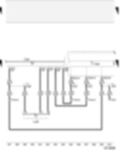
Wiring Diagram AUDI A4 2006 - Engine control unit - air mass meter - fuel system diagnostic pump G70 Air mass meter J623 Engine control unit N80 Activated charcoal filter system solenoid valve 1 T17d 17-pin connector, red, coupling station on electronics box, plenum chamber T121 121-pin connector, black V144 Fuel system diagnostic pump A100 Connection 2 (87), in dash panel wiring harness D172 Connection (engine electrics), in engine compartment wiring harness * for models with US equipment only ** applicable up to model year 2005 *** applicable from model year 2006
Wiring Diagram AUDI A4 2006 - Engine control unit - engine speed sender - knock sensor G28 Engine speed sender G61 Knock sensor 1 G66 Knock sensor 2 J623 Engine control unit T3 3-pin connector, grey, on engine block T3e 3-pin connector, blue, on engine block T3f 3-pin connector, black, on engine block T121 121-pin connector, black 104 Earth connection in front right wiring harness - sensor earth - 220 Earth connection (sender earth), in engine wiring harness
Wiring Diagram AUDI A4 2006 - Engine control unit - Hall sender - knock sensor G40 Hall sender G163 Hall sender 2 G198 Knock sensor 3 G199 Knock sensor 4 J623 Engine control unit T3b 3-pin connector, blue, on engine block T3g 3-pin connector, black, on engine block T121 121-pin connector, black 104 Earth connection in front right wiring harness - sensor earth - 220 Earth connection (sender earth), in engine wiring harness D141 Connection (5V), in engine wiring harness
Wiring Diagram AUDI A4 2006 - Engine control unit - Lambda probes G39 Lambda probe G130 Lambda probe after catalytic converter J623 Engine control unit T4a 4-pin connector, green, connector point lambda probe (bulkhead) T6 6-pin connector, black, connector point lambda probe (bulkhead) T121 121-pin connector, black Z19 Lambda probe heater Z29 Lambda probe 1 heater after catalytic converter 220 Earth connection (sender earth), in engine wiring harness
Wiring Diagram AUDI A4 2006 - Engine control unit - Lambda probes G108 Lambda probe 2 G131 Lambda probe 2 after catalytic converter J623 Engine control unit T4c 4-pin connector, brown, connector point lambda probe (bulkhead) T6a 6-pin connector, black, connector point lambda probe (bulkhead) T121 121-pin connector, black Z28 Lambda probe 2 heater Z30 Lambda probe 2 heater after catalytic converter 220 Earth connection (sender earth), in engine wiring harness
Wiring Diagram AUDI A4 2006 - Engine control unit - coolant temperature sender - exhaust flap valve - secondary air pump motor G2 Coolant temperature display sender G62 Coolant temperature sender J299 Secondary air pump relay J623 Engine control unit N220 Exhaust flap valve S130 Secondary air pump fuse T17j 17-pin connector, brown, coupling station on electronics box, plenum chamber T121 121-pin connector, black V101 Secondary air pump motor 220 Earth connection (sender earth), in engine wiring harness * only for models with automatic gearbox (AG6), is dropped, from model year 2006 ** phased-in modification *** No longer fitted, phased-in modification
Wiring Diagram AUDI A4 2006 - Engine control unit - accelerator position sender - throttle valve module - brake light switch F Brake light switch F36 Clutch pedal switch F47 Brake pedal switch G79 Accelerator position sender G185 Accelerator position sender 2 J338 Throttle valve module J527 Steering column electronics control unit J623 Engine control unit T16a 16-pin connector, black, on steering column electronics control unit T17d 17-pin connector, red, coupling station on electronics box, plenum chamber T17e 17-pin connector, white, coupling station on electronics box, plenum chamber T121 121-pin connector, black A18 Connection (54), in dash panel wiring harness A20 Positive connection (15a), in dash panel wiring harness * ⇒ applicable Current Flow Diagram: anti-lock brake system ** for models with manual gearbox only *** applicable from model year 2006
Wiring Diagram AUDI A4 2006 - Engine control unit - ignition coils J623 Engine control unit N70 Ignition coil 1 with output stage N127 Ignition coil 2 with output stage N291 Ignition coil 3 with output stage N292 Ignition coil 4 with output stage P Spark plug connector Q Spark plugs T121 121-pin connector, black 121 Earth connection 2, in front right wiring harness 343 Earth connection (ignition coil), in injection system wiring harness D102 Connection 2, in engine compartment wiring harness
Wiring Diagram AUDI A4 2006 - Engine control unit - ignition coils J623 Engine control unit N323 Ignition coil 5 with output stage N324 Ignition coil 6 with output stage N325 Ignition coil 7 with output stage N326 Ignition coil 8 with output stage P Spark plug connector Q Spark plugs S102 Engine control unit fuse T121 121-pin connector, black 83 Earth connection 1, in front right wiring harness 121 Earth connection 2, in front right wiring harness 343 Earth connection (ignition coil), in injection system wiring harness D102 Connection 2, in engine compartment wiring harness
Wiring Diagram AUDI A4 2006 - Engine control unit - automatic gearbox control unit - control unit in dash panel insert J217 Automatic gearbox control unit J285 Control unit in dash panel insert J623 Engine control unit T16 16-pin connector, black, diagnostic connector T17d 17-pin connector, red, coupling station on electronics box, plenum chamber T17e 17-pin connector, white, coupling station on electronics box, plenum chamber T32a 32-pin connector, green, on dash panel insert T121 121-pin connector, black A76 Connection (diagnosis wire K), in dash panel wiring harness A121 Connection (high bus), in dash panel wiring harness A122 Connection (low bus), in dash panel wiring harness D166 Connection (K-diagnosis wiring), in engine compartment wiring harness * for models with automatic gearbox (AG6) only ● Data bus wire (CAN bus)
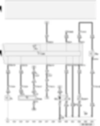
Wiring Diagram AUDI A4 2006 - Control unit in dash panel insert - oil pressure switch - coolant shortage indicator switch - fuel gauge sender - oil level and oil temperature sender F1 Oil pressure switch F66 Coolant shortage indicator switch G Fuel gauge sender G6 Fuel system pressurisation pump G169 Fuel gauge sender 2 G266 Oil level and oil temperature sender J285 Control unit in dash panel insert K2 Alternator warning lamp T17d 17-pin connector, red, coupling station on electronics box, plenum chamber T17e 17-pin connector, white, coupling station on electronics box, plenum chamber T32 32-pin connector, blue, on dash panel insert T32a 32-pin connector, green, on dash panel insert 249 Earth connection 2, in interior wiring harness 269 Earth connection (sender earth) 1, in dash panel wiring harness A17 Connection (61), in dash panel wiring harness A74 Connection (15a, fuse 5), in dash panel wiring harness * for models with four-wheel drive only ** output for signal earth *** applicable from model year 2006
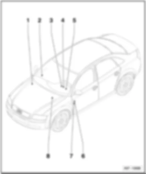
AUDI A4 2006 Overview of relay 2 -
q Components: -J4-, -J9-, -J17-, -J53-, -J59-, -J236-, -J569-, -J695-
q Location up to July 2004
q Location from August 2004
q Location component -J569- for engine code BNS
q Location component -J17- for some engine variants ⇒ Item , page
4 -
q Components: -J85-, -J182-, -J330-, -J408-, -J430-, -J461-, -J462-, -J463-, -J608-
q Components: -J17-, -J52-, -J151-, -J179-, -J207-, -J271-, -J299-, -J317-, -J363-, -J434-, -J496-, -J569-, -J757-
q Location for petrol engines, up to July 2004
q Location for diesel engines, up to July 2004
q Location for engine codes BKE, BRB, BNA, BLB, BRC, BPW, BVG, BVF, BRF, BRE, BVA, BRD
q Location for engine codes BSG, BPP, BTP, BKN, ASB
q Location for engine codes BGB, BPG, BWE, BWT, BUL, BPJ, BYK
q Location for engine code ALZ
q Location for engine code ALT
q Location for engine code BDG
q Location for engine codes BFB, BBK, BHF
q Location for engine code AWA
t Location for engine codes AUK, BKH
t Location for engine code BNS
t Location for engine code BBJ, with manual gearbox or multitronic
t Location for engine code BBJ with AG5
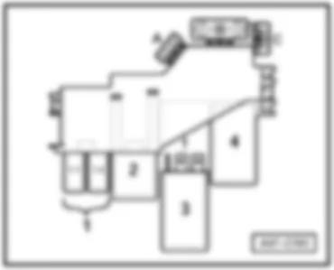
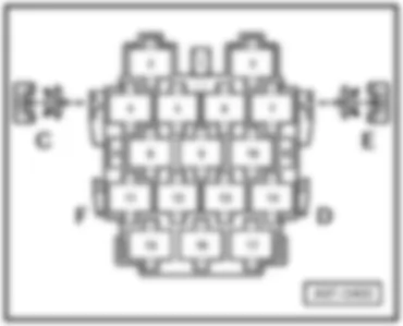
AUDI A4 2006 Position of relays, relay carrier (9-pin) with onboard supply control unit, up to July 2004 Driver side dash panel, behind the relay carrier (3-pin)
1 - Fuel pump relay -J17-
2 - Servotronic control unit -J236-
3 - Dual tone horn relay -J4-
4 - Brake servo relay -J569-
5 - Special vehicle control unit (driving school vehicle, taxi) -J608-
6 - X-contact relief relay -J59-
AUDI A4 2006 Position of relays, relay carrier (9-pin) with onboard supply control unit, from August 2004 Driver side dash panel, behind the relay carrier (3-pin)
1 - Fuel pump relay -J17-
2 - Servotronic control unit -J236-
3 - Starter motor relay 2 ¹) -J695-
4 - Starter motor relay ¹) -J53-
- Brake servo relay ²), ³) -J569-
5 - Heated rear window relay -J9-
6 - X-contact relief relay -J59-
8 - Dual tone horn relay -J4-
¹) for engine codes AUK, BKH, BNS only
²) not for engine codes AUK, BKH
³) applicable up to model year 2005
⁴) applicable from model year 2006
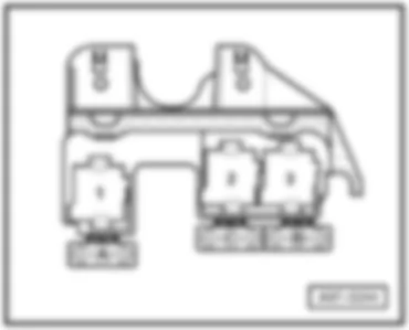
AUDI A4 2006 Position of relays, relay carrier (4-pin) with screw connection 3 - Engine power reduction relay 1 (driving school vehicle) -J662-
4 - Engine power reduction relay 2 (driving school vehicle) -J663-
- Alarm on and hands-free system control unit (taxi) -J610-
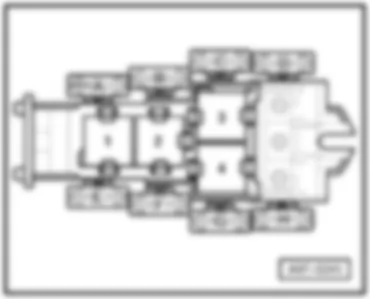
AUDI A4 2006 Position of relays, relay carrier (4-pin), petrol engines, up to July 2004 In electronics box in plenum chamber
1 - Automatic gearbox relay (multitronic) -J60-
1.1 - Continued coolant circulation relay (V6) -J151-
2 - Secondary air pump relay -J299-
3 - Motronic current supply relay -J271-
- Turbocharger coolant pump control unit -J155-
- Current supply relay for Simos control unit -J363-
4 - Automatic gearbox relay (AG5) -J60-
- Starter inhibitor and reversing light relay (multitronic/AG6) -J226-
- Starter inhibitor relay, clutch pedal switch -J434-
4.1 ¹) - Automatic gearbox relay (AG5) -J60-
- Starter inhibitor relay -J433-
- Starter inhibitor relay, clutch pedal switch -J434-
4.2 ¹) - Reversing light relay
¹) applicable from model year 2004
AUDI A4 2006 Position of relays, relay carrier (4-pin), diesel engines, up to July 2004 In electronics box in plenum chamber
1.2 - Fuel pump relay -J17-
2³) - Terminal 30 voltage supply relay -J317-
2 ⁴) - Glow plug relay -J52-
3 ³) - Automatic glow period control unit -J179-
3 ⁴) - Terminal 30 voltage supply relay -J317-
4 - Starter inhibitor and reversing light relay -J226-
- Automatic gearbox relay -J60-
4.1 - Automatic gearbox relay -J60-
E - Fan for control unit -V274-
¹) applicable from model year 2002
²) applicable from model year 2004
³) for models with engine code BKE only
⁴) not for models with engine code BKE
AUDI A4 2006 Position of relays, relay carrier (4-pin), engine codes BKE, BRB, BNA, BLB, BRC, BPW, BVG, BVF, BRF, BRE, BVA, BRD, from August 2004 1.1 - Fuel pump relay -J17-
1.2 - Starter inhibitor relay -J207-
2 - Terminal 30 voltage supply relay -J317-
3 - Automatic glow period control unit -J179-
AUDI A4 2006 Position of relays, relay carrier (4-pin), engine codes BSG, BPP, BTP, BKN, ASB, from August 2004 In electronics box in plenum chamber
1.1 - Fuel pump relay -J17-
1.2 - Starter inhibitor relay -J207-
2 - Terminal 30 voltage supply relay -J317-
3 - Automatic glow period control unit -J179-
AUDI A4 2006 Position of relays, relay carrier (4-pin), engine codes BGB, BPG, BWE, BWT, BUL, BPJ, BYK, from August 2004 In electronics box in plenum chamber
1.2 - Starter inhibitor relay -J217-
2 - Motronic current supply relay -J271-
3 - Engine component current supply relay -J757-
AUDI A4 2006 Position of relays, relay carrier (4-pin), engine code ALZ, from August 2004 In electronics box in plenum chamber
2 - Current supply relay for Simos control unit -J363-
3 - Secondary air pump relay -J299-
AUDI A4 2006 Position of relays, relay carrier (4-pin), engine code ALT, from August 2004 In electronics box in plenum chamber
2 - Motronic current supply relay -J271-
AUDI A4 2006 Position of relays, relay carrier (4-pin), engine code BDG, from August 2004 In electronics box in plenum chamber
1.1 - Fuel pump relay -J17-
1.2 - Starter inhibitor relay -J207-
2 - Terminal 30 voltage supply relay -J317-
3 - Glow plug relay -J52-
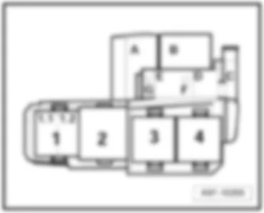
AUDI A4 2006 Position of relays, relay carrier (4-pin), engine codes BFB, BBK, BHF, from August 2004 In electronics box in plenum chamber
1.1 - Continued coolant circulation relay -J151-
1.2 - Starter inhibitor relay -J207-
- Starter inhibitor relay, clutch pedal switch ¹) -J434-
2 - Motronic current supply relay -J271-
3 - Secondary air pump relay -J299-
¹) For engine codes BBK, BHF only
AUDI A4 2006 Position of relays, relay carrier (4-pin), engine code AWA, from August 2004 In electronics box in plenum chamber
1.2 - Starter inhibitor relay -J207-
2 - Motronic current supply relay -J271-
AUDI A4 2006 Position of relays, relay carrier (4-pin), engine codes AUK, BKH, from August 2004 In electronics box in plenum chamber
1.1 - Additional coolant pump relay -J496-
2 - Motronic current supply relay -J271-
3 - Engine component current supply relay -J757-
AUDI A4 2006 Position of relays, relay carrier (4-pin), engine code BNS, from August 2004 In electronics box in plenum chamber
1.1 - Continued coolant circulation relay -J151-
1.2 - Brake servo relay -J569-
2 - Motronic current supply relay -J271-
3 - Engine component current supply relay -J757-
4 - Secondary air pump relay -J299-
AUDI A4 2006 Position of relays, relay carrier (4-pin), engine code BBJ, from August 2004 In electronics box in plenum chamber
1.1 - Continued coolant circulation relay ¹) -J151-
1.2 - Starter inhibitor relay ¹) -J207-
2 - Motronic current supply relay ¹) -J271-
3 - Secondary air pump relay ¹) -J299-
¹) for models with manual gearbox or with automatic gearbox (multitronic) only
AUDI A4 2006 Position of relays, relay carrier (4-pin), engine code BBJ, from August 2004 In electronics box in plenum chamber
1.1 - Continued coolant circulation relay ¹) -J151-
1.2 - Starter inhibitor relay ¹) -J207-
2 - Motronic current supply relay ¹) -J271-
3 - Secondary air pump relay ¹) -J299-
¹) for models with automatic gearbox (AG5) only
AUDI A4 2006 Position of relays, relay carrier for special vehicles 1 - Alarm system relay 2, main beam -J461-
2 - Taxi alarm system 2 control unit -J430-
3 - Alarm system control unit -J85-
4 - Alarm system control unit -J85-
5 - Alarm system relay 4, right turn signal -J463-
6 - Alarm system relay 3, left turn signal -J462-
AUDI A4 2006 Overview of fuses q Components: -S126-, -S328-
q Components: -S37-, -S45-, -S87-, -S100-, -S184-, -S280-
q Components: -S42-, -S51-, -S123-, -S214-
q Location up to July 2004
q Location from August 2004
q Components: -S1- up to -S22- and -S223- up to -S244-
q Location up to July 2004
q Location from August 2004
7 -
q Components: -S55-, -S57-, -S182-, -S183-, -S184-, -S291-, -S292-, -S293-, S294-, -S295-, -S296-, -S297-, -S298-
q Location for diesel engines, up to July 2004
q Location for engine codes BKE, BRB, BNA, BLB, BRC, BPW, BVG, BVF, BRF, BRE, BVA, BRD
q Location for engine codes BSG, BPP, BTP, BKN, ASB
q Location for engine codes BGB, BPG, BWE, BWT, BUL, BPJ, BYK
q Location for engine code ALZ
q Location for engine code ALT
q Location for engine code BDG
q Location for engine codes BFB, BBK, BHF
q Location for engine code AWA
t Location for engine codes AUK, BKH
t Location for engine code BNS
t Location for engine code BBJ, with manual gearbox or multitronic
t Location for engine code BBJ with AG5
AUDI A4 2006 Position of fuses, coupling station of A-pillar bottom right, behind the trim
E - Seat adjustment fuse -S46-
E - Seat adjustment fuse -S46- (with lumbar support adjustment)
AUDI A4 2006 Position of fuses, relay carrier (3-pin) A ¹) - Auxiliary heater fuse -S62-
B - Auxiliary heater fuse -S126-
C - Auxiliary heater fuse 2 -S328-
¹) applicable up to model year 2003
AUDI A4 2006 Position of fuses, relay carrier (9-pin) with onboard supply control unit Driver side dash panel, behind the relay carrier (3-pin)
A - Rear roller blind thermal fuse -S100-
B - Rear roller blind thermal fuse -S100-
B - Socket 1 fuse (driving school vehicle) -S184-
D - Window regulator single fuse 2 -S280-
E - Driver seat adjustment thermal fuse 2 -S45-
F - Window regulator single fuse -S37-
G - Trailer towing attachment thermal fuse -S87-
AUDI A4 2006 Position of fuses, relay carrier (4-pin) with screw connection, up to July 2004 B - Optional equipment: vermin repellent
E - Radiator fan run-on fuse -S214-
G - Radiator fan single fuse -S42-
H - ABS control unit fuse 1 -S123-
AUDI A4 2006 Position of fuses, relay carrier (4-pin) with screw connection, from August 2004 B - Optional equipment: vermin repellent
E - S51 - Fuse (driving school vehicle) ¹) -S51-
F - Fuse (driving school vehicle) ³) -S51-
- Radiator fan single fuse ¹)²) -S42-
G - Radiator fan run-on fuse¹)²) -S214-
- Radiator fan single fuse ⁴) -S42-
H - ABS control unit fuse 1 -S123-
¹) for engine codes BBK, BHF, BNS only
²) for engine codes BKN, ASB, BPP, BSG, BTP only
³) not for engine codes BBK, BHF
⁴) not for engine codes BKN, ASB, BPP, BSG, BTP, BBK, BHF
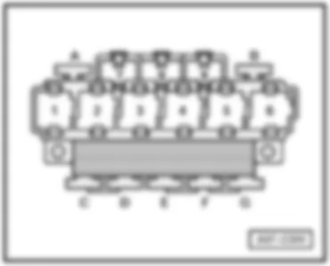
AUDI A4 2006 Position of fuses, relay carrier (4-pin), petrol engines, up to July 2004 In electronics box in plenum chamber
A - Engine electronics fuse -S282-
B - Secondary air pump fuse -S130-
C - Automatic gearbox fuse, run-on -S286-
AUDI A4 2006 Position of fuses, relay carrier (4-pin), diesel engines, up to July 2004 In electronics box in plenum chamber
A - Engine control unit fuse -S102-
- Engine electronics fuse -S282-
B - Engine glow plug strip fuse -S39-
C - Automatic gearbox fuse, run-on -S286-
- Engine control unit fuse ²) -S102-
D - Glow plug fuse 2 -S189-
F ¹) - Glow plug fuse 2 -S189-
¹) applicable from model year 2002
²) for models with engine code BKE only
Note:
The positions D and F are in the electronics box.
AUDI A4 2006 Position of fuses, relay carrier (4-pin), engine codes BKE, BRB, BNA, BLB, BRC, BPW, BVG, BVF, BRF, BRE, BVA, BRD, from August 2004 In electronics box in plenum chamber
A - Engine electronics fuse -S282-
B - Engine glow plug strip fuse -S39-
C - Engine control unit fuse -S102-
D - Automatic gearbox fuse, run-on -S286-
E - Engine electronics fuse 2 -S344-
AUDI A4 2006 Position of fuses, relay carrier (4-pin), engine codes BSG, BPP, BTP, BKN, ASB, from August 2004 In electronics box in plenum chamber
A - Engine electronics fuse -S282-
B - Engine glow plug strip fuse -S39-
C - Engine control unit fuse -S102-
D - Automatic gearbox fuse, run-on -S286-
E - Engine electronics fuse 2 -S344-
G - Engine electronics fuse 3 -S345-
AUDI A4 2006 Position of fuses, relay carrier (4-pin), engine codes BGB, BPG, BWE, BWT, BUL, BPJ, BYK, from August 2004 In electronics box in plenum chamber
A - Engine electronics fuse -S282-
B - Engine electronics fuse 3 -S345-
C - Engine control unit fuse -S102-
E - Engine electronics fuse 2 -S344-
G - Automatic gearbox fuse, run-on -S286-
AUDI A4 2006 Position of fuses, relay carrier (4-pin), engine code ALZ, from August 2004 In electronics box in plenum chamber
A - Engine electronics fuse 2 -S344-
B - Secondary air pump fuse -S130-
D - Engine control unit fuse -S102-
G - Engine electronics fuse -S282-
AUDI A4 2006 Position of fuses, relay carrier (4-pin), engine code ALT, from August 2004 In electronics box in plenum chamber
A - Engine electronics fuse 2 -S344-
B - Engine electronics fuse -S282-
C - Automatic gearbox fuse, run-on -S286-
D - Engine control unit fuse -S102-
AUDI A4 2006 Position of fuses, relay carrier (4-pin), engine code BDG, from August 2004 In electronics box in plenum chamber
A - Engine electronics fuse -S282-
B - Engine glow plug strip fuse -S39-
C - Automatic gearbox fuse, run-on -S286-
H¹) - Glow plug fuse 2 -S189-
¹) on the relay carrier underside
AUDI A4 2006 Position of fuses, relay carrier (4-pin), engine codes BFB, BBK, BHF, from August 2004 In electronics box in plenum chamber
A - Engine electronics fuse 2 -S344-
B - Secondary air pump fuse -S130-
C - Automatic gearbox fuse, run-on -S286-
D - Engine control unit fuse -S102-
G - Engine electronics fuse -S282-
H¹) - Heater fuse ²) -S23-
¹) on the relay carrier underside
AUDI A4 2006 Position of fuses, relay carrier (4-pin), engine code AWA, from August 2004 In electronics box in plenum chamber
A - Engine electronics fuse -S282-
B - Engine electronics fuse 2 -S344-
C - Automatic gearbox fuse, run-on -S286-
H ¹) - Engine electronics fuse 3 -S345-
¹) on the relay carrier underside
AUDI A4 2006 Position of fuses, relay carrier (4-pin), engine codes AUK, BKH, from August 2004 In electronics box in plenum chamber
A - Engine electronics fuse 2 -S344-
B - Engine electronics fuse -S282-
C - Engine control unit fuse -S102-
E - Lambda probe heating thermal fuse -S73-
G - Automatic gearbox fuse, run-on -S286-
AUDI A4 2006 Position of fuses, relay carrier (4-pin), engine code BNS, from August 2004 In electronics box in plenum chamber
A - Engine electronics fuse 2 -S344-
B - Engine electronics fuse -S282-
C - Engine control unit fuse -S102-
E - Lambda probe heating thermal fuse -S73-
? - Brake vacuum pump fuse -S283-
H ¹) - Secondary air pump fuse -S130-
¹) on the relay carrier underside
AUDI A4 2006 Position of fuses, relay carrier (4-pin), engine codes BBJ (with manual gearbox or multitronicВ®), from August 2004 In electronics box in plenum chamber
A - Engine electronics fuse 2 ¹) -S344-
B - Secondary air pump fuse ¹) -S130-
C - Automatic gearbox fuse, run-on ¹) -S286-
D - Engine control unit fuse¹) -S102-
E - Injector fuse ¹) -S116-
G - Engine electronics fuse ¹) -S282-
¹) for models with manual gearbox or with automatic gearbox (multitronic®) only
AUDI A4 2006 Position of fuses, relay carrier (4-pin), engine codes BBJ (with AG5), from August 2004 In electronics box in plenum chamber
A - Engine control unit fuse ¹) -S102-
B - Secondary air pump fuse ¹) -S130-
C - Engine electronics fuse ¹) -S282-
D - Engine electronics fuse 2 ¹) -S344-
E - Injector fuse ¹) -S116-
¹) for models with automatic gearbox (AG5) only
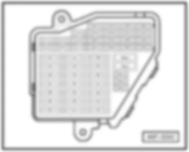
AUDI A4 2006 Position of fuses, fuse holder, up to July 2004 Note:
From fuse number 23 upwards the fuses in the fuse holder are designated as 223 in the Current Flow Diagram
Audi A4 Fitting Locations No. 802 / 27
No. Current Flow Diagram designation Nominal value Function/component Terminal 10 - S10 - Fuse in relay plate fuse holder 5 A - E102 - Headlight range control regulator 15 11 - S11 - Fuse in relay plate fuse holder 10 A - J234 - Airbag control unit 15 12 - S12 - Fuse in relay plate fuse holder 10 A - T16 - 16-pin connector, black, diagnostic connector 30 13 - S13 - Fuse in relay plate fuse holder 10 A - J527 - Steering column electronics control unit 30 14 - S14 - Fuse in relay plate fuse holder 10 A - F - Brake light switch 30 15 - S15 - Fuse in relay plate fuse holder 10 A - J285 - Control unit in dash panel insert 30 16 - S16 - Fuse in relay plate fuse holder 5 A - E284 - Garage door operating unit 15 17 - S17 - Fuse in relay plate fuse holder - Vacant 18 - S18 - Fuse in relay plate fuse holder - Vacant
Audi A4 Fitting Locations No. 802 / 29
No. Current Flow Diagram designation Nominal value Function/component Terminal 29 - S229 - Fuse on fuse holder 20 A - N70 - Ignition coil 1 with output stage 87 30 - S230 - Fuse on fuse holder 20 A - J245 - Sliding sunroof adjustment control unit 30 31 - S231 - Fuse on fuse holder 15 A - F125 - Multifunction switch 15 32 - S232 - Fuse on fuse holder 20 A - J583 - NOx sensor control unit 87 33 - S233 - Fuse on fuse holder 15 A - U1 - Cigarette lighter 30
Audi A4 Fitting Locations No. 802 / 31
No. Current Flow Diagram designation Nominal value Function/component Terminal 40 - S240 - Fuse on fuse holder 25 A - H2 - Treble tone horn 30 41 - S241 - Fuse on fuse holder 30 A - J364 - Auxiliary heater control unit 30 42 - S242 - Fuse on fuse holder 25 A - J104 - ABS control unit 30 43 - S243 - Fuse on fuse holder 15 A - J220 - Motronic control unit 15 44 - S244 - Fuse on fuse holder 30 A - E87 - Operating and display unit for air conditioning system/Climatronic 30
AUDI A4 2006 Position of fuses, fuse holder, from August 2004
Audi A4 Fitting Locations No. 802 / 34
No. Current Flow Diagram designation Nominal value Function/component Terminal 10 - S10 - Fuse in relay plate fuse holder 5 A - E102 - Headlight range control regulator 15 11 - S11 - Fuse in relay plate fuse holder 10 A - J234 - Airbag control unit 15 12 - S12 - Fuse in relay plate fuse holder 10 A - T16 - 16-pin connector, black, diagnostic connector 30 13 - S13 - Fuse in relay plate fuse holder 10 A - J527 - Steering column electronics control unit 30 14 - S14 - Fuse in relay plate fuse holder 10 A - F - Brake light switch 30 15 - S15 - Fuse in relay plate fuse holder 10 A - J285 - Control unit in dash panel insert 30 16 - S16 - Fuse in relay plate fuse holder 5 A - E284 - Garage door operating unit 15 17 - S17 - Fuse in relay plate fuse holder 10 A - G397 - Rain and light detector sensor 30 18 - S18 - Fuse in relay plate fuse holder 5 A - V318 - Left dynamic cornering light control motor 15
Audi A4 Fitting Locations No. 802 / 36
No. Current Flow Diagram designation Nominal value Function/component Terminal 29 - S229 - Fuse on fuse holder - Vacant 30 - S230 - Fuse on fuse holder 20 A - J245 - Sliding sunroof adjustment control unit 30 31 - S231 - Fuse on fuse holder 15 A - F4 - Reversing light switch 15 32 - S232 - Fuse on fuse holder 15 A - U10-Trailer socket ²) 75x 33 - S233 - Fuse on fuse holder 15 A - U1 - Cigarette lighter 30 34 - S234 - Fuse on fuse holder 30 A - U5 - 12 V socket 30 35 - S235 - Fuse on fuse holder 30 A - U - socket 30 36 - S236 - Fuse on fuse holder 30 A - J519 - Onboard power supply control unit 75x 37 - S237 - Fuse on fuse holder 30 A - J519 - Onboard power supply control unit 75x
Notes:
t ¹) applicable from February 2005
t ²) applicable from model year 2006
Audi A4 Fitting Locations No. 802 / 38
AUDI A4 2006 Position of fuses, fuse holder for special vehicle - taxi
AUDI A4 2006 Position of fuses, fuse holder for special vehicle - police
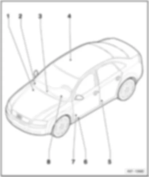
AUDI A4 2006 AUDI A4 2006 Overview of earth points in engine compartment
q only for 2.0 l FSI motor, location
q only for 2,5 l engine TDI, location
q only for 2.0 l FSI motor, location
q only for 3.0 l engine, location
Note:
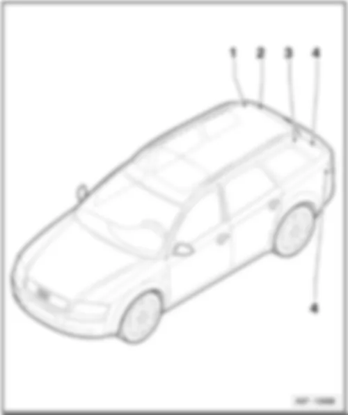
♦ Overview of luggage compartment - Avant models
1 - Earth point, right D-pillar -654-
3 - Earth point, left D-pillar -653-
5 - Earth point, on left in luggage compartment -50-
AUDI A4 2006 Earth point, in engine compartment 12 Earth point, in engine compartment, left -arrow-
only for 2,0 l engine FSI
12 Earth point, in engine compartment, left -arrow-
only for 2,5 l engine TDI
18 Earth point on engine block -arrow-
only for 2,0 l engine FSI
18 Earth point on engine block -arrow-
26 Earth point, on front apron -arrow-
AUDI A4 2006 Earth points, in interior 33 Earth point behind dash panel on right -arrow-
44 Earth point, lower part of left A-pillar -arrow-
77 Earth point, lower part of left B-pillar -arrow-
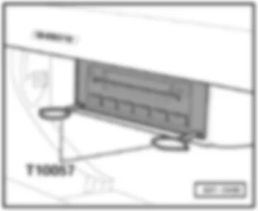
610 Earth point (audio), under centre console, front -arrow-
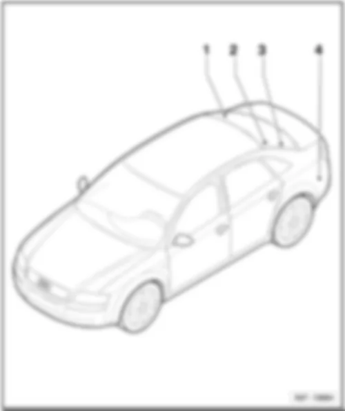
AUDI A4 2006 Earth point, in luggage compartment - saloon models
50 Earth point, on left in luggage compartment -arrow-
653 Earth point, left D-pillar -arrow-
701 Earth point, in luggage compartment -arrow-
Earth point, in luggage compartment - Avant models 50 Earth point, on left in luggage compartment -arrow-
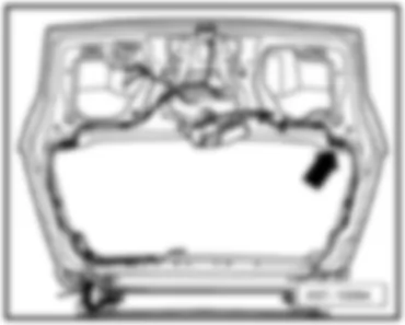
53 Earth point, on right in rear lid -arrow-
654 Earth point, right D-pillar -arrow-
AUDI A4 2006 Control units overview q Location for navigation system RNS-E
Diesel direct injection system control unit -J248-
17 - Automatic gearbox control unit -J217-
q for models with multitronic® only
AUDI A4 2006 Motronic control unit -J220-, diesel direct injection system control unit -J248-, Simos control unit -J361- On electronics box in plenum chamber
AUDI A4 2006 Automatic gearbox control unit -J217- In electronics box in plenum chamber
for models with multitronic® only
AUDI A4 2006 ABS control unit -J104- AUDI A4 2006 Radiator fan control unit -J293-
AUDI A4 2006 Fresh air blower control unit -J126- AUDI A4 2006 Headlight range control, control unit -J431- AUDI A4 2006 Steering column electronics control unit -J527- AUDI A4 2006 Display control unit in dash panel insert -J285- In the dash panel behind the display unit
AUDI A4 2006 Airbag control unit -J234- AUDI A4 2006 Onboard power supply control unit -J519- Behind driver's storage compartment
AUDI A4 2006 Trailer detector control unit -J345- AUDI A4 2006 Parking aid control unit -J446- In left luggage compartment, behind side trim, on apron
AUDI A4 2006 Navigation operating electronics control unit -J402- AUDI A4 2006 Navigation system with CD drive control unit -J401-
For navigation system RNS-E only
AUDI A4 2006 Control unit with display for radio and navigation system -J503-
for navigation system RNS-Low only
AUDI A4 2006 CD changer -R41-
AUDI A4 2006 Telephone and telematics control unit, telematics -J526- AUDI A4 2006 Language input control unit -J507-
AUDI A4 2006 Convenience system central control unit -J393-
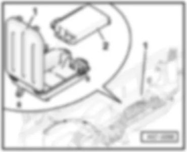
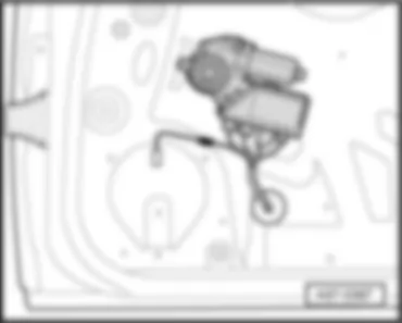
AUDI A4 2006 Driver door control unit -J386- AUDI A4 2006 Front passenger side door control unit -J387- In window regulator motor integrated
Can't find your car? Check -> DiagnostData.com !

