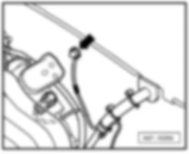
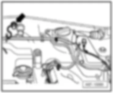
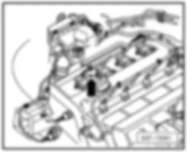
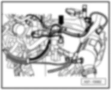
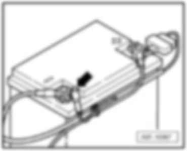
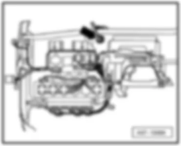
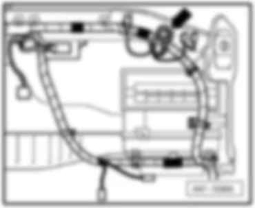
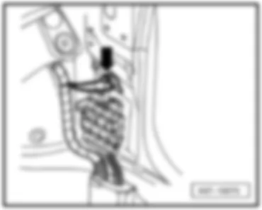
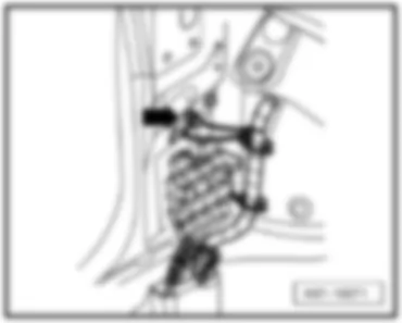
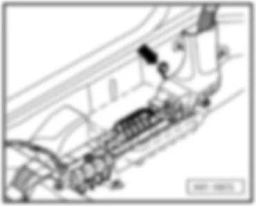
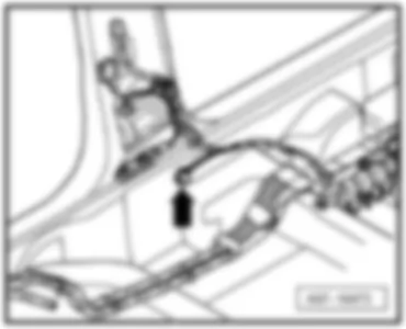
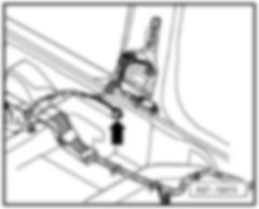
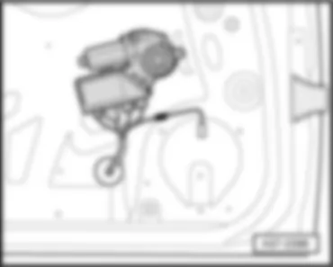
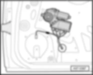
Wiring Diagram AUDI A4 2007 - Battery - starter - alternator

| A | Battery |
| B | Starter |
| C | Alternator |
| C1 | Voltage regulator |
| J207 | Starter inhibitor relay |
| J434 | Starter inhibitor relay, clutch pedal switch |
| S88 | Strip fuse |
| T4x | 4-pin connector, black, near to the battery |
| T17j | 17-pin connector, brown, coupling station on electronics box, plenum chamber |
| 11 | Earth point, in battery box |
| 500 | Screw connection 1 (30), on relay plate |
| * | for models with manual gearbox only |
| ** | for models with automatic gearbox only (AG6), ⇒ applicable Current Flow Diagram: automatic gearbox |
| *** | for models with US equipment only and manual gearbox, ⇒ applicable Current Flow Diagram starter inhibitor relay, clutch pedal switch |
Wiring Diagram AUDI A4 2007 - Ignition/starter switch - fuel pump relay - fuses
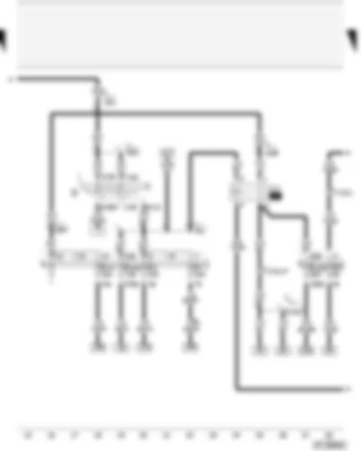
| D | Ignition/starter switch |
| J17 | Fuel pump relay |
| S4 | Fuse in relay plate fuse holder |
| S5 | Fuse in relay plate fuse holder |
| S7 | Fuse in relay plate fuse holder |
| S14 | Fuse in relay plate fuse holder |
| S228 | Fuse in fuse holder |
| S243 | Fuse in fuse holder |
| T17d | 17-pin connector, red, coupling station on electronics box, plenum chamber |
| T17j | 17-pin connector, brown, coupling station on electronics box, plenum chamber |
| 501 | Screw connection 2 (30), on relay plate |
| A2 | Positive connection (15), in dash panel wiring harness |
| A32 | Positive connection (30), in dash panel wiring harness |
| A57 | Positive connection 3 (30), in dash panel wiring harness |
| A98 | Positive connection 4 (30), in dash panel wiring harness |
| D103 | Connection 3, in engine compartment wiring harness |
| * | applicable from model year 2006 |
Wiring Diagram AUDI A4 2007 - Engine control unit - Motronic current supply relay - inlet camshaft control valve 1 - continued coolant circulation pump
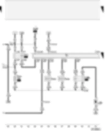
| J151 | Continued coolant circulation relay |
| J271 | Motronic current supply relay |
| J623 | Engine control unit |
| N205 | Inlet camshaft control valve 1 |
| N208 | Inlet camshaft control valve 2 |
| S286 | Automatic gearbox fuse, run-on |
| S344 | Engine electronics fuse 2 |
| T17d | 17-pin connector, red, coupling station on electronics box, plenum chamber |
| T17j | 17-pin connector, brown, coupling station on electronics box, plenum chamber |
| T121 | 121-pin connector, black |
| V51 | Continued coolant circulation pump |
| D50 | Positive connection (30), in engine compartment wiring harness |
| D101 | Connection 1, in engine compartment wiring harness |
| D106 | Connection 4, in engine compartment wiring harness |
| * | for models with automatic gearbox (AG6) only |
| ** | for countries with hot climate only |
Wiring Diagram AUDI A4 2007 - Engine control unit - injectors
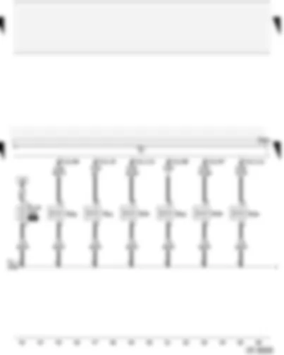
| J623 | Engine control unit |
| N30 | Injector, cylinder 1 |
| N31 | Injector, cylinder 2 |
| N32 | Injector, cylinder 3 |
| N33 | Injector, cylinder 4 |
| N83 | Injector, cylinder 5 |
| N84 | Injector, cylinder 6 |
| S116 | Injector fuse |
| T121 | 121-pin connector, black |
| D95 | Connection (injectors), in engine compartment wiring harness |
Wiring Diagram AUDI A4 2007 - Engine control unit - injectors - secondary air inlet valve - electro-hydraulic engine mounting solenoid valve - variable intake manifold change-over valve
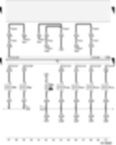
| J293 | Radiator fan control unit |
| J623 | Engine control unit |
| J671 | Radiator fan control unit 2 |
| N85 | Injector, cylinder 7 |
| N86 | Injector, cylinder 8 |
| N112 | Secondary air inlet valve |
| N144 | Left electrohydraulic engine mounting solenoid valve |
| N145 | Right electrohydraulic engine mounting solenoid valve |
| N156 | Variable intake manifold change-over valve |
| S282 | Engine electronics fuse |
| T4y | 4-pin connector, black, in engine compartment |
| T6n | 6-pin connector, on radiator fan control unit -2- |
| T6o | 6-pin connector, on radiator fan control unit |
| T10d | 10-pin connector, grey, coupling station on left of A-pillar |
| T17d | 17-pin connector, red, coupling station on electronics box, plenum chamber |
| T17j | 17-pin connector, brown, coupling station on electronics box, plenum chamber |
| T121 | 121-pin connector, black |
| D95 | Connection (injectors), in engine compartment wiring harness |
| D172 | Connection (engine electrics), in engine compartment wiring harness |
Wiring Diagram AUDI A4 2007 - Engine control unit - air mass meter - fuel system diagnostic pump
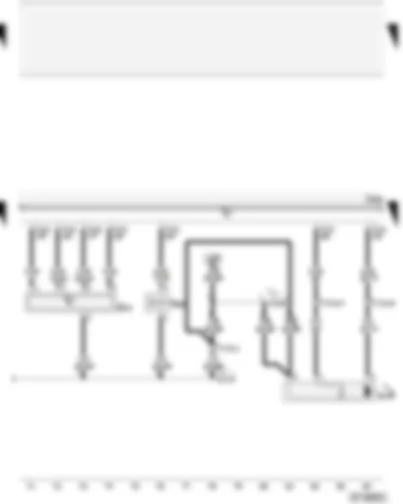
| G70 | Air mass meter |
| J623 | Engine control unit |
| N80 | Activated charcoal filter system solenoid valve 1 |
| T17d | 17-pin connector, red, coupling station on electronics box, plenum chamber |
| T121 | 121-pin connector, black |
| V144 | Fuel system diagnostic pump |
| A100 | Connection 2 (87), in dash panel wiring harness |
| D172 | Connection (engine electrics), in engine compartment wiring harness |
| * | for models with US equipment only |
| ** | applicable up to model year 2005 |
| *** | applicable from model year 2006 |
Wiring Diagram AUDI A4 2007 - Engine control unit - engine speed sender - knock sensor
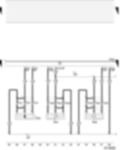
| G28 | Engine speed sender |
| G61 | Knock sensor 1 |
| G66 | Knock sensor 2 |
| J623 | Engine control unit |
| T3 | 3-pin connector, grey, on engine block |
| T3e | 3-pin connector, blue, on engine block |
| T3f | 3-pin connector, black, on engine block |
| T121 | 121-pin connector, black |
| 104 | Earth connection in front right wiring harness - sensor earth - |
| 220 | Earth connection (sender earth), in engine wiring harness |
Wiring Diagram AUDI A4 2007 - Engine control unit - Hall sender - knock sensor
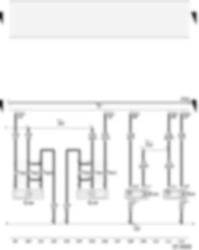
| G40 | Hall sender |
| G163 | Hall sender 2 |
| G198 | Knock sensor 3 |
| G199 | Knock sensor 4 |
| J623 | Engine control unit |
| T3b | 3-pin connector, blue, on engine block |
| T3g | 3-pin connector, black, on engine block |
| T121 | 121-pin connector, black |
| 104 | Earth connection in front right wiring harness - sensor earth - |
| 220 | Earth connection (sender earth), in engine wiring harness |
| D141 | Connection (5V), in engine wiring harness |
Wiring Diagram AUDI A4 2007 - Engine control unit - Lambda probes
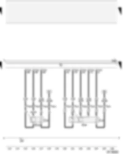
| G39 | Lambda probe |
| G130 | Lambda probe after catalytic converter |
| J623 | Engine control unit |
| T4a | 4-pin connector, green, connector point lambda probe (bulkhead) |
| T6 | 6-pin connector, black, connector point lambda probe (bulkhead) |
| T121 | 121-pin connector, black |
| Z19 | Lambda probe heater |
| Z29 | Lambda probe 1 heater after catalytic converter |
| 220 | Earth connection (sender earth), in engine wiring harness |
Wiring Diagram AUDI A4 2007 - Engine control unit - Lambda probes
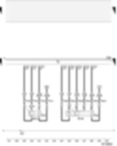
| G108 | Lambda probe 2 |
| G131 | Lambda probe 2 after catalytic converter |
| J623 | Engine control unit |
| T4c | 4-pin connector, brown, connector point lambda probe (bulkhead) |
| T6a | 6-pin connector, black, connector point lambda probe (bulkhead) |
| T121 | 121-pin connector, black |
| Z28 | Lambda probe 2 heater |
| Z30 | Lambda probe 2 heater after catalytic converter |
| 220 | Earth connection (sender earth), in engine wiring harness |
Wiring Diagram AUDI A4 2007 - Engine control unit - coolant temperature sender - exhaust flap valve - secondary air pump motor
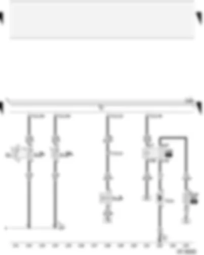
| G2 | Coolant temperature display sender |
| G62 | Coolant temperature sender |
| J299 | Secondary air pump relay |
| J623 | Engine control unit |
| N220 | Exhaust flap valve |
| S130 | Secondary air pump fuse |
| T17j | 17-pin connector, brown, coupling station on electronics box, plenum chamber |
| T121 | 121-pin connector, black |
| V101 | Secondary air pump motor |
| 12 | Earth point, on left in engine compartment |
| 220 | Earth connection (sender earth), in engine wiring harness |
| * | only for models with automatic gearbox (AG6), is dropped, from model year 2006 |
| ** | phased-in modification |
| *** | No longer fitted, phased-in modification |
Wiring Diagram AUDI A4 2007 - Engine control unit - accelerator position sender - throttle valve module - brake light switch
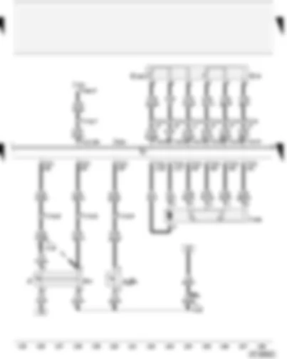
| F | Brake light switch |
| F36 | Clutch pedal switch |
| F47 | Brake pedal switch |
| G79 | Accelerator position sender |
| G185 | Accelerator position sender 2 |
| J338 | Throttle valve module |
| J527 | Steering column electronics control unit |
| J623 | Engine control unit |
| T16a | 16-pin connector, black, on steering column electronics control unit |
| T17d | 17-pin connector, red, coupling station on electronics box, plenum chamber |
| T17e | 17-pin connector, white, coupling station on electronics box, plenum chamber |
| T121 | 121-pin connector, black |
| A18 | Connection (54), in dash panel wiring harness |
| A20 | Positive connection (15a), in dash panel wiring harness |
| * | ⇒ applicable Current Flow Diagram: anti-lock brake system |
| ** | for models with manual gearbox only |
| *** | applicable from model year 2006 |
Wiring Diagram AUDI A4 2007 - Engine control unit - ignition coils
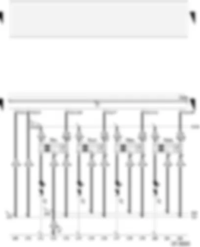
| J623 | Engine control unit |
| N70 | Ignition coil 1 with output stage |
| N127 | Ignition coil 2 with output stage |
| N291 | Ignition coil 3 with output stage |
| N292 | Ignition coil 4 with output stage |
| P | Spark plug connector |
| Q | Spark plugs |
| T121 | 121-pin connector, black |
| 19 | Earth point, near coil |
| 121 | Earth connection 2, in front right wiring harness |
| 343 | Earth connection (ignition coil), in injection system wiring harness |
| D102 | Connection 2, in engine compartment wiring harness |
Wiring Diagram AUDI A4 2007 - Engine control unit - ignition coils
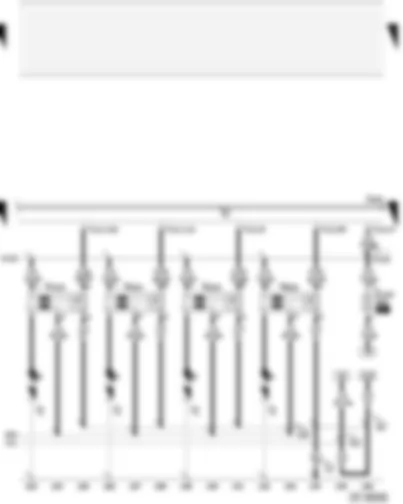
| J623 | Engine control unit |
| N323 | Ignition coil 5 with output stage |
| N324 | Ignition coil 6 with output stage |
| N325 | Ignition coil 7 with output stage |
| N326 | Ignition coil 8 with output stage |
| P | Spark plug connector |
| Q | Spark plugs |
| S102 | Engine control unit fuse |
| T121 | 121-pin connector, black |
| 12 | Earth point, on left in engine compartment |
| 83 | Earth connection 1, in front right wiring harness |
| 121 | Earth connection 2, in front right wiring harness |
| 343 | Earth connection (ignition coil), in injection system wiring harness |
| D102 | Connection 2, in engine compartment wiring harness |
Wiring Diagram AUDI A4 2007 - Engine control unit - automatic gearbox control unit - control unit in dash panel insert
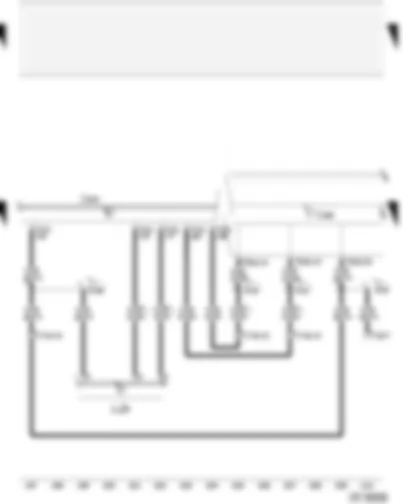
| J217 | Automatic gearbox control unit |
| J285 | Control unit in dash panel insert |
| J623 | Engine control unit |
| T16 | 16-pin connector, black, diagnostic connector |
| T17d | 17-pin connector, red, coupling station on electronics box, plenum chamber |
| T17e | 17-pin connector, white, coupling station on electronics box, plenum chamber |
| T32a | 32-pin connector, green, on dash panel insert |
| T121 | 121-pin connector, black |
| A76 | Connection (diagnosis wire K), in dash panel wiring harness |
| A121 | Connection (high bus), in dash panel wiring harness |
| A122 | Connection (low bus), in dash panel wiring harness |
| D166 | Connection (K-diagnosis wiring), in engine compartment wiring harness |
| * | for models with automatic gearbox (AG6) only |
| ● | Data bus wire (CAN bus) |
Wiring Diagram AUDI A4 2007 - Control unit in dash panel insert - oil pressure switch - coolant shortage indicator switch - fuel gauge sender - oil level and oil temperature sender
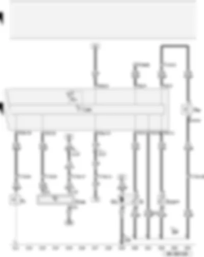
| F1 | Oil pressure switch |
| F66 | Coolant shortage indicator switch |
| G | Fuel gauge sender |
| G6 | Fuel system pressurisation pump |
| G169 | Fuel gauge sender 2 |
| G266 | Oil level and oil temperature sender |
| J285 | Control unit in dash panel insert |
| K2 | Alternator warning lamp |
| T17d | 17-pin connector, red, coupling station on electronics box, plenum chamber |
| T17e | 17-pin connector, white, coupling station on electronics box, plenum chamber |
| T32 | 32-pin connector, blue, on dash panel insert |
| T32a | 32-pin connector, green, on dash panel insert |
| 249 | Earth connection 2, in interior wiring harness |
| 269 | Earth connection (sender earth) 1, in dash panel wiring harness |
| A17 | Connection (61), in dash panel wiring harness |
| A74 | Connection (15a, fuse 5), in dash panel wiring harness |
| * | for models with four-wheel drive only |
| ** | output for signal earth |
| *** | applicable from model year 2006 |
AUDI A4 2007 Overview of relay
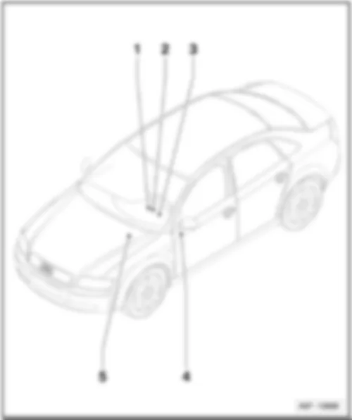
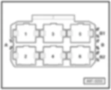
| 1 - | Relay carrier (3-pin) |
| q | Components: -J359-, -J360-, -J608- |
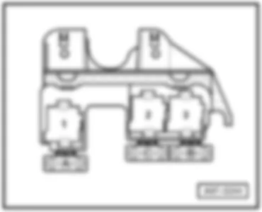
| q | Location → page 803/4 |
| 2 - | Relay carrier (9-pin) with onboard supply control unit |
| q | Components: -J4-, -J9-, -J17-, -J53-, -J59-, -J236-, -J569-, -J695- |
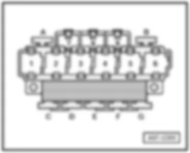
| q | Location up to July 2004 → page 803/5 |
| q | Location from August 2004 → page 803/6 |
| q | Location component -J569- for engine code BNS → page 803/19 |
| q | Location component -J17- for some engine variants ⇒ Item → 5 , page → 803/2 |
| 3 - | Relay carrier (4-pin) with screw connection |
| q | Components: -J662-, -J663-, -J610- |
| q | Location → page 803/7 |
| 4 - | Relay carrier for special vehicles |
| q | Components: -J85-, -J182-, -J330-, -J408-, -J430-, -J461-, -J462-, -J463-, -J608- |
| q | Location → page 803/22 |
| Audi A4 | Fitting Locations | No. 803 / 2 |
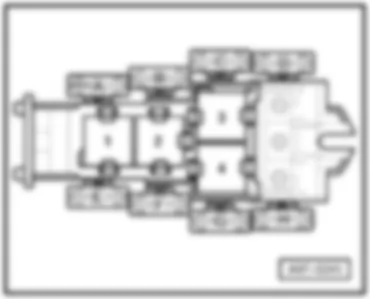
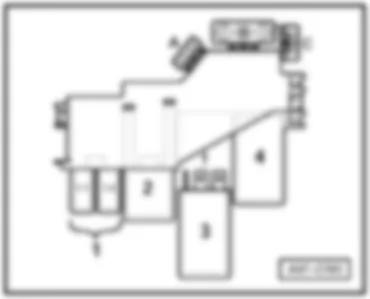
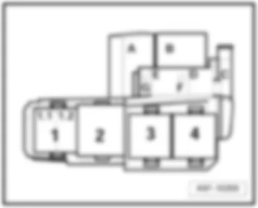
| 5 - | Relay carrier (4-pin) |
| q | Components: -J17-, -J52-, -J151-, -J179-, -J207-, -J271-, -J299-, -J317-, -J363-, -J434-, -J496-, -J569-, -J757- |
| q | Location for petrol engines, up to July 2004 → page 803/8 |
| q | Location for diesel engines, up to July 2004 → page 803/9 |
| q | Location for engine codes BKE, BRB, BNA, BLB, BRC, BPW, BVG, BVF, BRF, BRE, BVA, BRD → page 803/10 |
| q | Location for engine codes BSG, BPP, BTP, BKN, ASB → page 803/11 |
| q | Location for engine codes BGB, BPG, BWE, BWT, BUL, BPJ, BYK → page 803/12 |
| q | Location for engine code ALZ → page 803/13 |
| q | Location for engine code ALT → page 803/14 |
| q | Location for engine code BDG → page 803/15 |
| q | Location for engine codes BFB, BBK, BHF → page 803/16 |
| q | Location for engine code AWA → page 803/17 |
| Audi A4 | Fitting Locations | No. 803 / 3 |
| t | Location for engine codes AUK, BKH → page 803/18 |
| t | Location for engine code BNS → page 803/19 |
| t | Location for engine code BBJ, with manual gearbox or multitronic → page 803/20 |
| t | Location for engine code BBJ with AG5 → page 803/21 |
| Audi A4 | Fitting Locations | No. 803 / 4 |
|
|
| Audi A4 | Fitting Locations | No. 803 / 5 |
|
|
| Audi A4 | Fitting Locations | No. 803 / 6 |
|
|
| Audi A4 | Fitting Locations | No. 803 / 7 |
|
| Audi A4 | Fitting Locations | No. 803 / 8 |
|
|
| Audi A4 | Fitting Locations | No. 803 / 9 |
|
|
| Audi A4 | Fitting Locations | No. 803 / 10 |
|
|
| Audi A4 | Fitting Locations | No. 803 / 11 |
|
|
| Audi A4 | Fitting Locations | No. 803 / 12 |
|
|
| Audi A4 | Fitting Locations | No. 803 / 13 |
|
|
| Audi A4 | Fitting Locations | No. 803 / 14 |
|
|
| Audi A4 | Fitting Locations | No. 803 / 15 |
|
|
| Audi A4 | Fitting Locations | No. 803 / 16 |
|
|
| Audi A4 | Fitting Locations | No. 803 / 17 |
|
|
| Audi A4 | Fitting Locations | No. 803 / 18 |
|
|
| Audi A4 | Fitting Locations | No. 803 / 19 |
|
|
| Audi A4 | Fitting Locations | No. 803 / 20 |
|
|
| Audi A4 | Fitting Locations | No. 803 / 21 |
|
|
| Audi A4 | Fitting Locations | No. 803 / 22 |
|
|