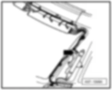
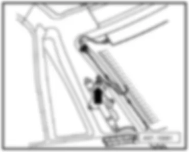
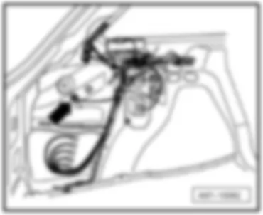
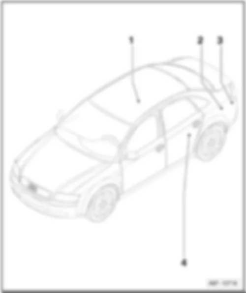
Wiring Diagram AUDI A4 2006 - Fuses

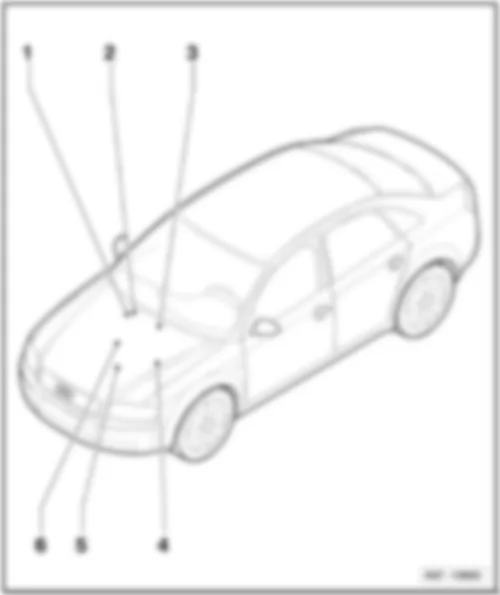
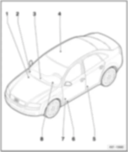
| S2 | Fuse in relay plate fuse holder |
| S22 | Fuse in relay plate fuse holder |
| S37 | Window regulator single fuse |
| S223 | Fuse in fuse holder |
| S224 | Fuse in fuse holder |
| S280 | Window regulator single fuse 2 |
| 33 | Earth point, on right behind dash panel |
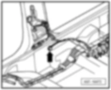
| 44 | Earth point, lower part of left A-pillar |
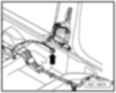
| 78 | Earth point, lower part of right B-pillar |
| 238 | Earth connection 1, in interior wiring harness |
| 249 | Earth connection 2, in interior wiring harness |
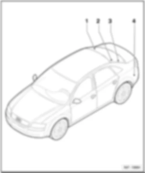
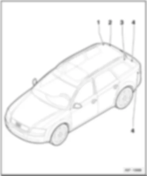
| 347 | Earth connection, in roof wiring harness |
| 501 | Screw connection 2 (30), on relay plate |
| A32 | Positive connection (30), in dash panel wiring harness |
| A57 | Positive connection 3 (30), in dash panel wiring harness |
| A98 | Positive connection 4 (30), in dash panel wiring harness |
| * | for models with solar roof cross-section 4,0 possible |
Wiring Diagram AUDI A4 2006 - Convenience system central control unit - alarm horn
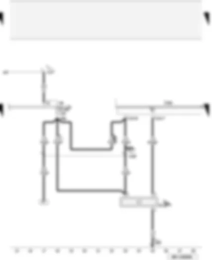
| H12 | Alarm horn |
| J393 | Convenience system central control unit |
| S238 | Fuse in fuse holder |
| T12h | 12-pin connector, black, on convenience system central control unit |
| 249 | Earth connection 2, in interior wiring harness |
| A57 | Positive connection 3 (30), in dash panel wiring harness |
| A66 | Connection (30a, CL/ATA/IR), in dash panel wiring harness |
| * | for models with anti-theft alarm system only (DWA), not for US equipment |
| *** | for models with US equipment only |
| **** | not for models with US equipment |
Wiring Diagram AUDI A4 2006 - Handbrake warning - rear lid release
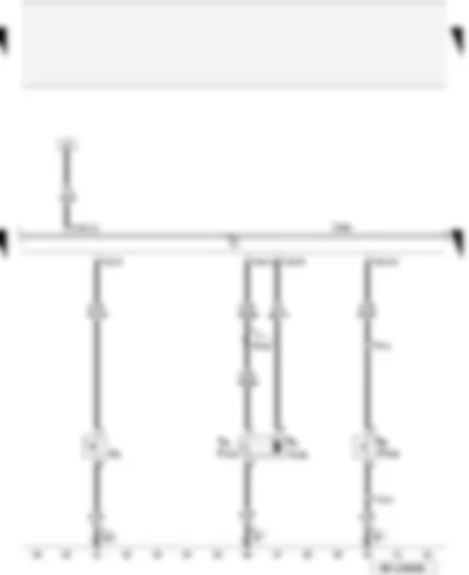
| F9 | Handbrake warning switch |
| F123 | Rear lid contact switch for anti-theft alarm system |
| F248 | Release button for rear lid lock cylinder |
| J393 | Convenience system central control unit |
| V139 | Rear lid release motor |
| T4l | 4-pin connector, black, in rear lid |
| T12h | 12-pin connector, black, on convenience system central control unit |
| T12i | 12-pin connector, black, on convenience system central control unit |
| T16i | 16-pin connector, brown, on convenience system central control unit |
| 87 | Earth connection 2, in rear wiring harness |
| 135 | Earth connection 2, in dash panel wiring harness |
| B154 | Connection 1 (DCt), in interior wiring harness |
| ** | for Avant models ⇒ see applicable Current Flow Diagram: Avant models, rear |
Wiring Diagram AUDI A4 2006 - Interior monitor deactivation - K-diagnosis wiring
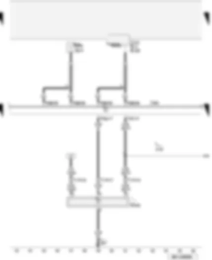
| G303 | Interior monitor send and receive module 1 |
| J393 | Convenience system central control unit |
| J515 | Aerial selection control unit |
| R11 | Aerial |
| R47 | Central locking and anti-theft alarm system aerial |
| R108 | Left aerial module |
| T16i | 16-pin connector, brown, on convenience system central control unit |
| T17f | 17-pin connector, orange, coupling station on left of A-pillar |
| T20g | 20-pin connector, red, on convenience system central control unit |
| 347 | Earth connection, in roof wiring harness |
| A76 | Connection (diagnosis wire K), in dash panel wiring harness |
| * | for models with anti-theft alarm system only (DWA), not for US equipment |
| **** | for models without radio only |
| ***** | ⇒ applicable Current Flow Diagram for radio / radio-navigation system or Avant |
Wiring Diagram AUDI A4 2006 - Bonnet contact switch - diagnostic connector
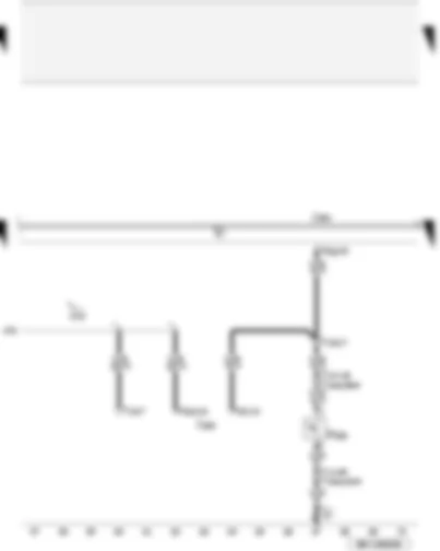
| F266 | Bonnet contact switch |
| J285 | Control unit in dash panel insert |
| J393 | Convenience system central control unit |
| T10d | 10-pin connector, grey, coupling station on left of A-pillar |
| T10ac | 10-pin connector, black, in left engine compartment |
| T14 | 14-pin connector, black, on left in engine compartment |
| T16 | 16-pin connector, black, diagnostic connector |
| T20g | 20-pin connector, red, on convenience system central control unit |
| T32 | 32-pin connector, blue, on dash panel insert |
| T32a | 32-pin connector, green, on dash panel insert |
| 12 | Earth point, on left in engine compartment |
| A76 | Connection (diagnosis wire K), in dash panel wiring harness |
| # | applicable up to model year 2006 |
| ## | applicable from model year 2007 |
Wiring Diagram AUDI A4 2006 - Tank filler flap locking - Airbag control unit - sliding sunroof adjustment control unit - reversing light switch
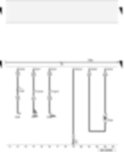
| F4 | Reversing light switch |
| J234 | Airbag control unit |
| J245 | Sliding sunroof adjustment control unit |
| J393 | Convenience system central control unit |
| V155 | Tank filler flap locking motor |
| T12h | 12-pin connector, black, on convenience system central control unit |
| T12i | 12-pin connector, black, on convenience system central control unit |
| T17d | 17-pin connector, red, coupling station on electronics box, plenum chamber |
| T17g | 17-pin connector, dark brown, coupling station on left of A-pillar |
| 81 | Earth connection 1, in dash panel wiring harness |
| * | for models with 5-speed manual gearbox (not for all engine versions) only |
| ** | for models with 6-speed manual gearbox (not for all engine versions) only |
| *** | ⇒ applicable Current Flow Diagram: automatic gearbox |
| **** | for models with sliding/tilting sunroof |
Wiring Diagram AUDI A4 2006 - Rear central switch for interior locking - contact switch in lock cylinder for rear lid - anti-theft alarm system - central locking system
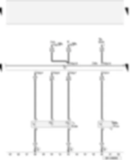
| E286 | Rear central switch for interior locking |
| F124 | Contact switch in lock cylinder for rear lid, anti-theft alarm system, central locking system |
| G184 | Rear right side window glass breakage sensor |
| J393 | Convenience system central control unit |
| J401 | Navigation system with CD drive control unit |
| R | Radio |
| T8 | 8-connector, black, radio connector III |
| T16i | 16-pin connector, brown, on convenience system central control unit |
| T16j | 16-pin connector, black, connector D |
| T20g | 20-pin connector, red, on convenience system central control unit |
| 81 | Earth connection 1, in dash panel wiring harness |
| 87 | Earth connection 2, in rear wiring harness |
| * | for models with rear central switch for interior locking only |
| ** | for Avant models ⇒ see applicable Current Flow Diagram: Avant models, rear |
| *** | for models with anti-theft alarm system (ATA) only |
| **** | applicable for saloon models |
Wiring Diagram AUDI A4 2006 - Interior lights - reading lights
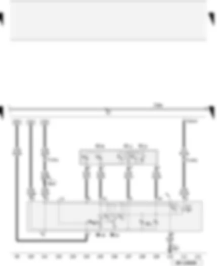
| J393 | Convenience system central control unit |
| T12h | 12-pin connector, black, on convenience system central control unit |
| T17f | 17-pin connector, orange, coupling station on left of A-pillar |
| W1 | Front interior light |
| W11 | Rear left reading light |
| W12 | Rear right reading light |
| W13 | Front passenger side reading light |
| W19 | Driver side reading light |
| W43 | Rear interior light |
| 347 | Earth connection, in roof wiring harness |
| B270 | Connection (58s), in roof wiring harness |
| * | for models with sliding/tilting sunroof, ⇒ applicable Current Flow Diagram |
Wiring Diagram AUDI A4 2006 - Illuminated vanity mirror - glove compartment light - luggage compartment light
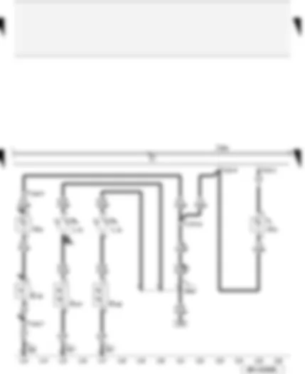
| E26 | Glove compartment light switch |
| F147 | Driver vanity mirror contact switch |
| F148 | Front passenger side vanity mirror contact switch |
| J393 | Convenience system central control unit |
| L31 | Vanity mirror light bulb |
| T12d | 12-pin connector, brown, near glove compartment |
| T12h | 12-pin connector, black, on convenience system central control unit |
| T17f | 17-pin connector, orange, coupling station on left of A-pillar |
| W3 | Luggage compartment light |
| W6 | Glove compartment light |
| 238 | Earth connection 1, in interior wiring harness |
| 347 | Earth connection, in roof wiring harness |
| B250 | Positive connection in roof wiring harness |
| * | for Avant models ⇒ see applicable Current Flow Diagram: Avant models, rear |
| ** | models with illuminated vanity mirror only |
| *** | ⇒ applicable Current Flow Diagram: garage door operation 'HomeLink' |
Wiring Diagram AUDI A4 2006 - Footwell lights
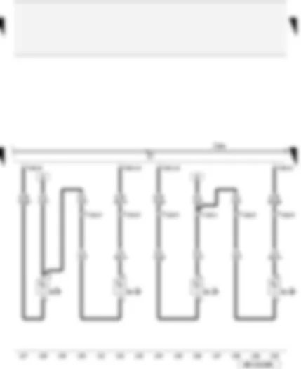
| J393 | Convenience system central control unit |
| T10o | 10-pin connector, red, coupling station seat wiring, driver seat |
| T10p | 10-pin connector, red, coupling station seat wiring, front passenger seat |
| T12d | 12-pin connector, brown, near glove compartment |
| T16h | 16-pin connector, black, on convenience system central control unit |
| W9 | Left footwell light |
| W10 | Right footwell light |
| W45 | Rear left footwell light |
| W46 | Rear right footwell light |
| * | for models with 'interior light package' only |
Wiring Diagram AUDI A4 2006 - Rear left central locking lock unit for models with rear mechanical window regulator
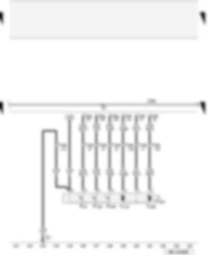
| F10 | Rear left door contact switch |
| F132 | Rear left central locking actuator |
| F222 | Rear left central locking lock unit |
| F245 | Rear left door central locking actuator for deadlock function |
| J393 | Convenience system central control unit |
| T16h | 16-pin connector, black, on convenience system central control unit |
| T20b | 20-pin connector, black, door B-pillar left |
| T20g | 20-pin connector, red, on convenience system central control unit |
| V115 | Rear left door central locking motor |
| V163 | Rear left door central locking deadlock function motor |
| 77 | Earth point, lower part of left B-pillar |
| * | only for models with central locking lock and rear mechanical window regulator |
Wiring Diagram AUDI A4 2006 - Rear right central locking lock unit for models with rear mechanical window regulator
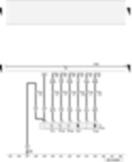
| F11 | Rear right door contact switch |
| F134 | Rear right central locking actuator |
| F223 | Rear right central locking lock unit |
| F246 | Rear right door central locking actuator for deadlock function |
| J393 | Convenience system central control unit |
| T16h | 16-pin connector, black, on convenience system central control unit |
| T20c | 20-pin connector, black, door B-pillar right |
| T20g | 20-pin connector, red, on convenience system central control unit |
| V97 | Rear right door central locking motor |
| V164 | Rear right door central locking deadlock function motor |
| 249 | Earth connection 2, in interior wiring harness |
| * | only for models with central locking lock and rear mechanical window regulator |
Wiring Diagram AUDI A4 2006 - Rear left door opener illumination - rear left entry light - rear left door warning lamp for models with rear mechanical window regulator
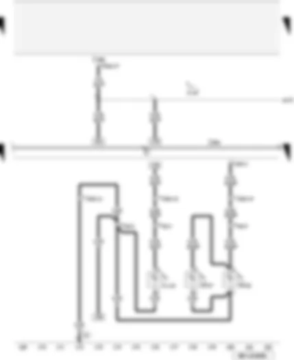
| J285 | Control unit in dash panel insert |
| J393 | Convenience system central control unit |
| L110 | Rear left door opener illumination bulb |
| T4p | 4-pin connector, black, in rear left door |
| T16h | 16-pin connector, black, on convenience system central control unit |
| T20b | 20-pin connector, black, door B-pillar left |
| T32a | 32-pin connector, green, on dash panel insert |
| W33 | Rear left entry light |
| W37 | Rear left door warning lamp |
| 77 | Earth point, lower part of left B-pillar |
| A175 | Connection (58s), in dash panel wiring harness |
| * | only for models with 'interior light package' and rear mechanical window regulator |
Wiring Diagram AUDI A4 2006 - Rear right door opener illumination - rear right entry light - rear right door warning lamp for models with rear mechanical window regulator
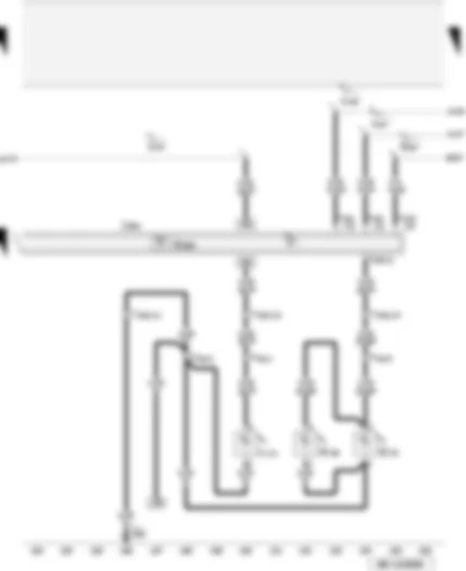
| G384 | Vehicle inclination sender |
| J393 | Convenience system central control unit |
| L111 | Rear right door opener illumination bulb |
| T4q | 4-pin connector, black, in rear right door |
| T12h | 12-pin connector, black, on convenience system central control unit |
| T16h | 16-pin connector, black, on convenience system central control unit |
| T16i | 16-pin connector, brown, on convenience system central control unit |
| T20c | 20-pin connector, black, door B-pillar right |
| W34 | Rear right entry light |
| W38 | Rear right door warning lamp |
| 249 | Earth connection 2, in interior wiring harness |
| A146 | Connection (convenience CAN bus, high), in dash panel wiring harness |
| A147 | Connection (convenience CAN bus, low), in dash panel wiring harness |
| A175 | Connection (58s), in dash panel wiring harness |
| B207 | Connection (convenience), in interior wiring harness |
| * | only for models with 'interior light package' and rear mechanical window regulator |
Wiring Diagram AUDI A4 2006 - Window regulator switch - in driver door
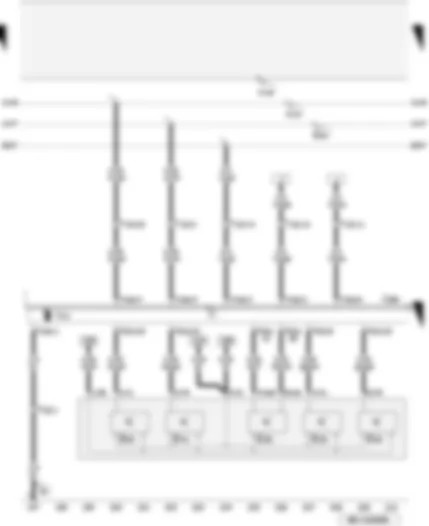
| E39 | Rear window regulator isolation switch |
| E40 | Front left window regulator switch |
| E41 | Front right window regulator switch |
| E53 | Rear left window regulator switch, in driver door |
| E55 | Rear right window regulator switch, in driver door |
| J386 | Driver door control unit |
| T10e | 10-pin connector, black, on door control unit, driver door |
| T20 | 20-pin connector, black, door A-pillar left |
| T32c | 32-pin connector, grey, driver side door control unit |
| V14 | Left window regulator motor |
| 44 | Earth point, lower part of left A-pillar |
| A146 | Connection (convenience CAN bus, high), in dash panel wiring harness |
| A147 | Connection (convenience CAN bus, low), in dash panel wiring harness |
| B207 | Connection (convenience), in interior wiring harness |
Wiring Diagram AUDI A4 2006 - Driver side - door warning and entry light - driver side central locking lock unit
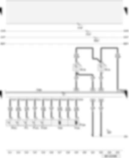
| F2 | Driver door contact switch |
| F131 | Front left central locking actuator |
| F220 | Driver side central locking lock unit |
| F241 | Driver side contact switch in lock cylinder |
| F243 | Driver door central locking actuator for deadlock function |
| J386 | Driver door control unit |
| T12 | 12-pin connector, black, on door control unit, driver door |
| T32c | 32-pin connector, grey, driver side door control unit |
| V56 | Driver door central locking motor |
| V161 | Driver door central locking deadlock function motor |
| W30 | Driver side door warning lamp |
| W31 | Front left entry light |
| 205 | Earth connection, in driver door wiring harness |
| A146 | Connection (convenience CAN bus, high), in dash panel wiring harness |
| A147 | Connection (convenience CAN bus, low), in dash panel wiring harness |
| B207 | Connection (convenience), in interior wiring harness |
| * | for models with 'interior light package' only |
Wiring Diagram AUDI A4 2006 - Driver seat memory operating unit
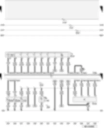
| E97 | Driver seat memory operating unit |
| E150 | Driver side interior locking switch |
| E204 | Tank filler flap remote release switch |
| E233 | Rear lid remote release button |
| J386 | Driver door control unit |
| L76 | Button illumination bulb |
| L108 | Driver door opener illumination bulb |
| T32c | 32-pin connector, grey, driver side door control unit |
| 205 | Earth connection, in driver door wiring harness |
| A146 | Connection (convenience CAN bus, high), in dash panel wiring harness |
| A147 | Connection (convenience CAN bus, low), in dash panel wiring harness |
| B207 | Connection (convenience), in interior wiring harness |
| R52 | Connection (58s), in driver side door wiring harness |
| * | for models with driver seat memory operating and exterior mirror only |
| ** | for models with 'interior light package' only |
Wiring Diagram AUDI A4 2006 - exterior mirror adjustment driver side without electric fold-in feature
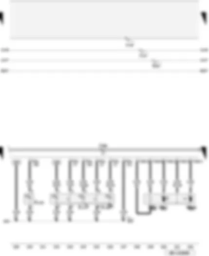
| E183 | Interior monitoring deactivation switch |
| E217 | Alarm system off switch |
| J386 | Driver door control unit |
| K133 | Central locking deadlock function warning lamp |
| T16b | 16-pin connector, door control unit, driver door |
| T32c | 32-pin connector, grey, driver side door control unit |
| V17 | Driver side mirror adjustment motor |
| V149 | Driver side mirror adjustment motor |
| Z4 | Driver side heated exterior mirror |
| 205 | Earth connection, in driver door wiring harness |
| A146 | Connection (convenience CAN bus, high), in dash panel wiring harness |
| A147 | Connection (convenience CAN bus, low), in dash panel wiring harness |
| B207 | Connection (convenience), in interior wiring harness |
| * | for models with anti-theft alarm system (ATA) only |
| ** | for models with interior monitoring deactivation switch only |
| *** | for models without electric folding exterior mirror only |
Wiring Diagram AUDI A4 2006 - Exterior mirror adjustment driver side with electric fold-in feature - mirror adjustment switch
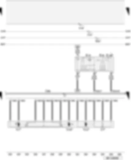
| E43 | Mirror adjustment switch |
| E48 | Mirror adjustment change-over switch |
| E168 | Adjustment switch for mirror with fold-in feature |
| J386 | Driver door control unit |
| T16b | 16-pin connector, door control unit, driver door |
| T32c | 32-pin connector, grey, driver side door control unit |
| V17 | Driver side mirror adjustment motor |
| V121 | Driver side folding mirror motor |
| V149 | Driver side mirror adjustment motor |
| Z4 | Driver side heated exterior mirror |
| A146 | Connection (convenience CAN bus, high), in dash panel wiring harness |
| A147 | Connection (convenience CAN bus, low), in dash panel wiring harness |
| B207 | Connection (convenience), in interior wiring harness |
| * | for models with electric folding exterior mirror only |
Wiring Diagram AUDI A4 2006 - Automatic anti-dazzle interior mirror
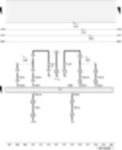
| J386 | Driver door control unit |
| T10e | 10-pin connector, black, on door control unit, driver door |
| T10f | 10-pin connector, black, on door control unit, front passenger door |
| T17f | 17-pin connector, orange, coupling station on left of A-pillar |
| T20 | 20-pin connector, black, door A-pillar left |
| T20a | 20-pin connector, black, door A-pillar right |
| Y7 | Automatic anti-dazzle interior mirror |
| A146 | Connection (convenience CAN bus, high), in dash panel wiring harness |
| A147 | Connection (convenience CAN bus, low), in dash panel wiring harness |
| A187 | Connection 1 (automatic anti-dazzle interior mirror), in dash panel wiring harness |
| A188 | Connection 2 (automatic anti-dazzle interior mirror), in dash panel wiring harness |
| B207 | Connection (convenience), in interior wiring harness |
| * | for models with automatic anti-dazzle interior mirror only |
| ** | ⇒ applicable Current Flow Diagram: garage door operation 'HomeLink' |
| *** | ⇒ applicable Current Flow Diagram for models with driver seat memory operating and exterior mirror |
Wiring Diagram AUDI A4 2006 - Front passenger side central locking lock unit
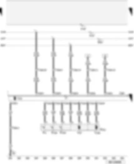
| F3 | Front passenger door contact switch |
| F133 | Front right central locking actuator |
| F221 | Front passenger side central locking lock unit |
| F244 | Front passenger door central locking actuator for deadlock function |
| J387 | Front passenger door control unit |
| T10f | 10-pin connector, black, on door control unit, front passenger door |
| T12a | 12-pin connector, black, on door control unit, front passenger door |
| T20a | 20-pin connector, black, door A-pillar right |
| V15 | Right window regulator motor |
| V57 | Front passenger door central locking motor |
| V162 | Front passenger door central locking deadlock function motor |
| 43 | Earth point, lower part of right A-pillar |
| A146 | Connection (convenience CAN bus, high), in dash panel wiring harness |
| A147 | Connection (convenience CAN bus, low), in dash panel wiring harness |
| B207 | Connection (convenience), in interior wiring harness |
Wiring Diagram AUDI A4 2006 - Exterior mirror adjustment front passenger side with electric fold-in feature
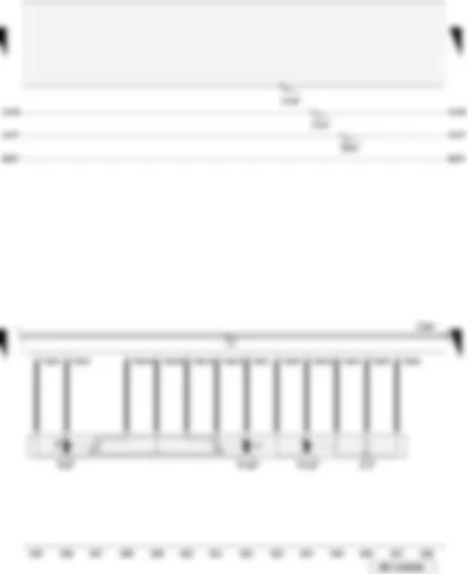
| J387 | Front passenger door control unit |
| T16c | 16-pin connector, door control unit, front passenger door |
| V25 | Front passenger side mirror adjustment motor |
| V122 | Front passenger side folding mirror motor |
| V150 | Front passenger side mirror adjustment motor |
| Z5 | Front passenger side heated exterior mirror |
| A146 | Connection (convenience CAN bus, high), in dash panel wiring harness |
| A147 | Connection (convenience CAN bus, low), in dash panel wiring harness |
| B207 | Connection (convenience), in interior wiring harness |
| * | for models with electric folding exterior mirror only |
Wiring Diagram AUDI A4 2006 - Exterior mirror adjustment front passenger side without electric fold-in feature - window regulator switch in front passenger door
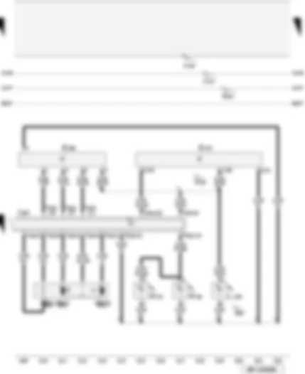
| E107 | Window regulator switch in front passenger door |
| E198 | Front passenger side interior locking switch |
| J387 | Front passenger door control unit |
| L109 | Front passenger door opener illumination bulb |
| T16c | 16-pin connector, door control unit, front passenger door |
| T32d | 32-pin connector, grey, front passenger side door control unit |
| V25 | Front passenger side mirror adjustment motor |
| V150 | Front passenger side mirror adjustment motor |
| W32 | Front right entry light |
| W36 | Front passenger side door warning lamp |
| Z5 | Front passenger side heated exterior mirror |
| 206 | Earth connection, in door wiring harness, front passenger side |
| A146 | Connection (convenience CAN bus, high), in dash panel wiring harness |
| A147 | Connection (convenience CAN bus, low), in dash panel wiring harness |
| B207 | Connection (convenience), in interior wiring harness |
| R53 | Connection (58s), in front passenger side door wiring harness |
| * | for models with 'interior light package' only |
| *** | for models without electric folding exterior mirror only |
Wiring Diagram AUDI A4 2006 - Rear left window regulator motor - rear left entry light - rear left door control unit for models with rear electric window regulator
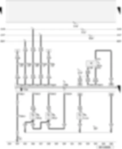
| E52 | Rear left window regulator switch, in door |
| J388 | Rear left door control unit |
| L110 | Rear left door opener illumination bulb |
| T10g | 10-pin connector, black, on door control unit, rear left |
| T16d | 16-pin connector, brown, rear left door control unit |
| T20b | 20-pin connector, black, door B-pillar left |
| V26 | Rear left window regulator motor |
| W33 | Rear left entry light |
| W37 | Rear left door warning lamp |
| 77 | Earth point, lower part of left B-pillar |
| 207 | Earth connection, in rear left door wiring harness |
| A146 | Connection (convenience CAN bus, high), in dash panel wiring harness |
| A147 | Connection (convenience CAN bus, low), in dash panel wiring harness |
| B207 | Connection (convenience), in interior wiring harness |
| R54 | Connection (58s), in rear left door wiring harness |
| * | for models with rear electric window regulator only |
| ** | only for models with 'interior light package' and rear electric window regulator |
Wiring Diagram AUDI A4 2006 - Rear left central locking lock unit for models with rear electric window regulator
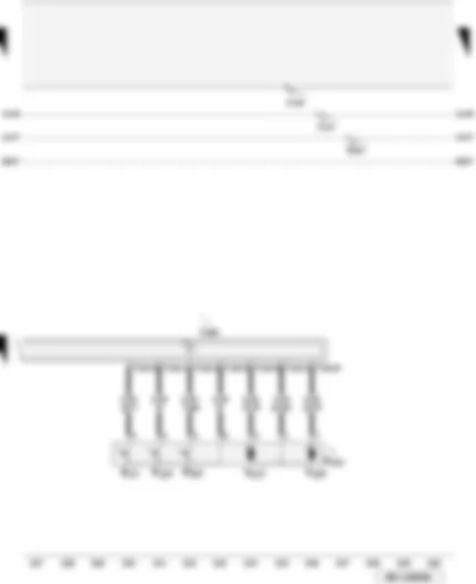
| F10 | Rear left door contact switch |
| F132 | Rear left central locking actuator |
| F222 | Rear left central locking lock unit |
| F245 | Rear left door central locking actuator for deadlock function |
| J388 | Rear left door control unit |
| T12b | 12-pin connector, black, on door control unit, rear left |
| V115 | Rear left door central locking motor |
| V163 | Rear left door central locking deadlock function motor |
| A146 | Connection (convenience CAN bus, high), in dash panel wiring harness |
| A147 | Connection (convenience CAN bus, low), in dash panel wiring harness |
| B207 | Connection (convenience), in interior wiring harness |
| * | for models with rear electric window regulator only |
Wiring Diagram AUDI A4 2006 - Rear right window regulator motor - rear right entry light - rear right door control unit for models with rear electric window regulator
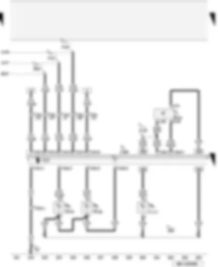
| E54 | Rear right window regulator switch, in door |
| J389 | Rear right door control unit |
| L111 | Rear right door opener illumination bulb |
| T10h | 10-pin connector, black, on door control unit, rear right |
| T16e | 16-pin connector, brown, rear right door control unit |
| T20c | 20-pin connector, black, door B-pillar right |
| V27 | Rear right window regulator motor |
| W34 | Rear right entry light |
| W38 | Rear right door warning lamp |
| 78 | Earth point, lower part of right B-pillar |
| 208 | Earth connection, in rear right door wiring harness |
| A146 | Connection (convenience CAN bus, high), in dash panel wiring harness |
| A147 | Connection (convenience CAN bus, low), in dash panel wiring harness |
| B207 | Connection (convenience), in interior wiring harness |
| R55 | Connection (58s), in rear right door wiring harness |
| * | for models with rear electric window regulator only |
| ** | only for models with 'interior light package' and rear electric window regulator |
Wiring Diagram AUDI A4 2006 - Rear right central locking lock unit for models with rear electric window regulator
| F11 | Rear right door contact switch |
| F134 | Rear right central locking actuator |
| F223 | Rear right central locking lock unit |
| F246 | Rear right door central locking actuator for deadlock function |
| J389 | Rear right door control unit |
| T12c | 12-pin connector, black, on door control unit, rear right |
| V97 | Rear right door central locking motor |
| V164 | Rear right door central locking deadlock function motor |
| * | for models with rear electric window regulator only |
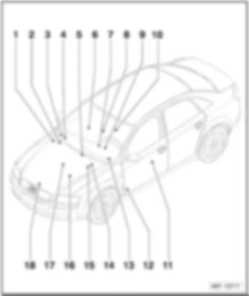
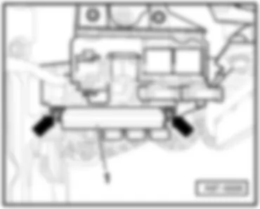
AUDI A4 2006 Overview of fuses
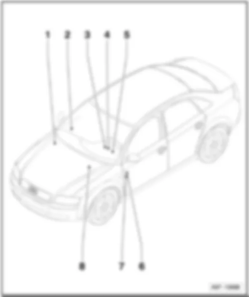
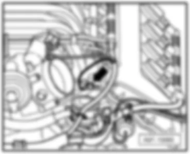
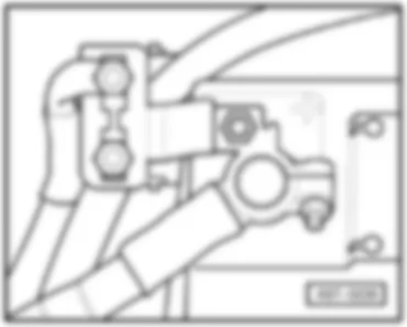
| 1 - | Main fuse: Strip fuse -S88- |
| q | Location → page 802/5 |
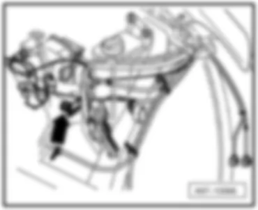
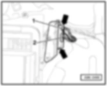
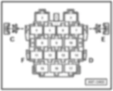
| 2 - | Coupling station of A-pillar |
| q | Components: -S46- |
| q | Location → page 802/6 |
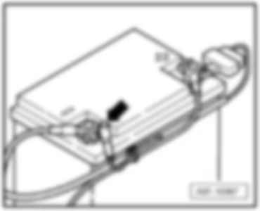
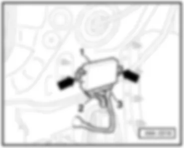
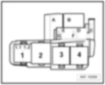
| 3 - | Relay carrier (3-pin) |
| q | Components: -S126-, -S328- |
| q | Location → page 802/7 |
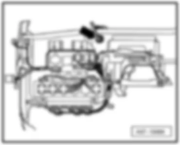
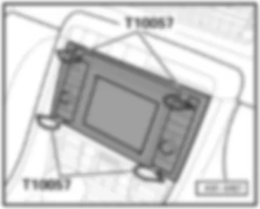
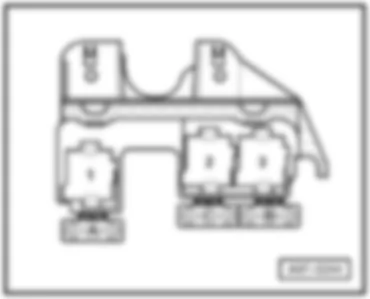
| 4 - | Relay carrier (9-pin) with onboard supply control unit |
| q | Components: -S37-, -S45-, -S87-, -S100-, -S184-, -S280- |
| q | Location → page 802/8 |
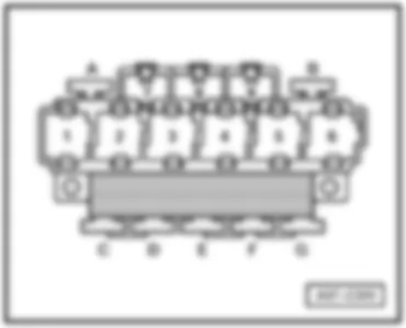
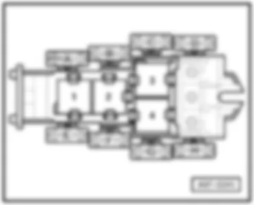
| 5 - | Relay carrier (4-pin) with screw connection |
| q | Components: -S42-, -S51-, -S123-, -S214- |
| q | Location up to July 2004 → page 802/9 |
| q | Location from August 2004 → page 802/10 |
| Audi A4 | Fitting Locations | No. 802 / 2 |
| 6 - | Fuse holder |
| q | Components: -S1- up to -S22- and -S223- up to -S244- |
| q | Location up to July 2004 → page 802/25 |
| q | Location from August 2004 → page 802/32 |
| 7 - | Fuse holder for special vehicles |
| q | Components: -S55-, -S57-, -S182-, -S183-, -S184-, -S291-, -S292-, -S293-, S294-, -S295-, -S296-, -S297-, -S298- |
| q | Location taxi → page 802/38 |
| q | Location police → page 802/39 |
| Audi A4 | Fitting Locations | No. 802 / 3 |
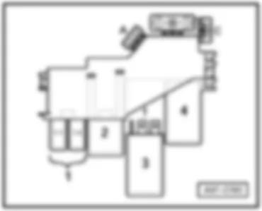
| 8 - | Relay carrier (4-pin) |
| q | Components: -S23-, -S39-, -S73-, -S102-, -S116-, -S130-, -S131-, -S189-, -S282-, -S283-, -S286-, -S344-, -S345- |
| q | Location for petrol engines, up to July 2004 → page 802/11 |
| q | Location for diesel engines, up to July 2004 → page 802/12 |
| q | Location for engine codes BKE, BRB, BNA, BLB, BRC, BPW, BVG, BVF, BRF, BRE, BVA, BRD → page 802/13 |
| q | Location for engine codes BSG, BPP, BTP, BKN, ASB → page 802/14 |
| q | Location for engine codes BGB, BPG, BWE, BWT, BUL, BPJ, BYK → page 802/15 |
| q | Location for engine code ALZ → page 802/16 |
| q | Location for engine code ALT → page 802/17 |
| q | Location for engine code BDG → page 802/18 |
| q | Location for engine codes BFB, BBK, BHF → page 802/19 |
| q | Location for engine code AWA → page 802/20 |
| Audi A4 | Fitting Locations | No. 802 / 4 |
| t | Location for engine codes AUK, BKH → page 802/21 |
| t | Location for engine code BNS → page 802/22 |
| t | Location for engine code BBJ, with manual gearbox or multitronic → page 802/23 |
| t | Location for engine code BBJ with AG5 → page 802/24 |
| Audi A4 | Fitting Locations | No. 802 / 5 |
|
|
| Audi A4 | Fitting Locations | No. 802 / 6 |
|
|
| Audi A4 | Fitting Locations | No. 802 / 7 |
|
|
| Audi A4 | Fitting Locations | No. 802 / 8 |
|
|
| Audi A4 | Fitting Locations | No. 802 / 9 |
|
|
| Audi A4 | Fitting Locations | No. 802 / 10 |
|
|
| Audi A4 | Fitting Locations | No. 802 / 11 |
|
|
| Audi A4 | Fitting Locations | No. 802 / 12 |
|
Note:
|
| Audi A4 | Fitting Locations | No. 802 / 13 |
|
| Audi A4 | Fitting Locations | No. 802 / 14 |
|
|
| Audi A4 | Fitting Locations | No. 802 / 15 |
|
|
| Audi A4 | Fitting Locations | No. 802 / 16 |
|
|
| Audi A4 | Fitting Locations | No. 802 / 17 |
|
|
| Audi A4 | Fitting Locations | No. 802 / 18 |
|
|
| Audi A4 | Fitting Locations | No. 802 / 19 |
|
|
| Audi A4 | Fitting Locations | No. 802 / 20 |
|
|
| Audi A4 | Fitting Locations | No. 802 / 21 |
|
|
| Audi A4 | Fitting Locations | No. 802 / 22 |
|
|
| Audi A4 | Fitting Locations | No. 802 / 23 |
|
|
| Audi A4 | Fitting Locations | No. 802 / 24 |
|
|
| Audi A4 | Fitting Locations | No. 802 / 25 |
|
Note:
|
| Audi A4 | Fitting Locations | No. 802 / 26 |
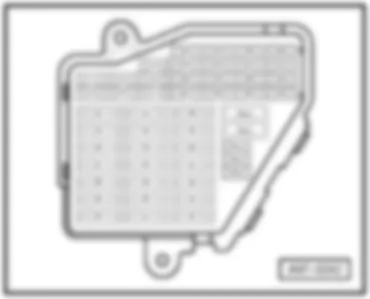
| Position of fuses, up to July 2004: |
| No. | Current Flow Diagram designation | Nominal value | Function/component | Terminal | ||
| 1 | - | S1 - Fuse in relay plate fuse holder | 10 A | - | J255 - Climatronic control unit | 30 |
| 2 | - | S2 - Fuse in relay plate fuse holder | 5 A | - | W9 - Left footwell light W10 - Right footwell light W45 - Rear left footwell light W46 - Rear right footwell light | 30 |
| 3 | - | S3 - Fuse in relay plate fuse holder | 5 A | - | Z20 - Left washer jet heater element Z21 - Right washer jet heater element | 75x |
| 4 | - | S4 - Fuse in relay plate fuse holder | 5 A | - | J293 - Radiator fan control unit J671 - Radiator fan control unit 2 | 87 |
| 5 | - | S5 - Fuse in relay plate fuse holder | 10 A | - | E128 - Heated rear left seat switch with regulator E129 - Heated rear right seat switch with regulator F189 - Tiptronic switch G226 - Oil level and oil temperature sender | 15 |
| 6 | - | S6 - Fuse in relay plate fuse holder | 5 A | - | G65 - High-pressure sender G238 - Air quality sensor | 15 |
| 7 | - | S7 - Fuse in relay plate fuse holder | 10 A | - | E132 - Traction control system switch F36 - Clutch pedal switch F47 - Brake pedal switch J104 - ABS control unit | 15 |
| 8 | - | S8 - Fuse in relay plate fuse holder | 5 A | - | R36 - Telephone transmitter and receiver unit R86 - Aerial amplifier for mobile telephone | 30 |
| 9 | - | S9 - Fuse in relay plate fuse holder | 15 A | - | J569 - Brake servo relay | 30 |
| Audi A4 | Fitting Locations | No. 802 / 27 |
| No. | Current Flow Diagram designation | Nominal value | Function/component | Terminal | ||
| 10 | - | S10 - Fuse in relay plate fuse holder | 5 A | - | E102 - Headlight range control regulator J431 - Headlight range control, control unit J668 - Power output module for right headlight V48 - Left headlight range control motor V49 - Right headlight range control motor | 15 |
| 11 | - | S11 - Fuse in relay plate fuse holder | 10 A | - | J234 - Airbag control unit J706 - Seat occupied recognition control unit K145 - Front passenger side airbag deactivated warning lamp | 15 |
| 12 | - | S12 - Fuse in relay plate fuse holder | 10 A | - | T16 - 16-pin connector, black, diagnostic connector | 30 |
| 13 | - | S13 - Fuse in relay plate fuse holder | 10 A | - | J527 - Steering column electronics control unit | 30 |
| 14 | - | S14 - Fuse in relay plate fuse holder | 10 A | - | F - Brake light switch | 30 |
| 15 | - | S15 - Fuse in relay plate fuse holder | 10 A | - | J285 - Control unit in dash panel insert | 30 |
| 16 | - | S16 - Fuse in relay plate fuse holder | 5 A | - | E284 - Garage door operating unit J530 - Garage door operation control unit | 15 |
| 17 | - | S17 - Fuse in relay plate fuse holder | - | Vacant | ||
| 18 | - | S18 - Fuse in relay plate fuse holder | - | Vacant |
| Audi A4 | Fitting Locations | No. 802 / 28 |
| No. | Current Flow Diagram designation | Nominal value | Function/component | Terminal | ||
| 19 | - | S19 - Fuse in relay plate fuse holder | 15 A | - | E1 - Lighting switch | 75x |
| 20 | - | S20 - Fuse in relay plate fuse holder | 15 A | - | J85 - Alarm system control unit J344 - Right gas discharge light control unit M31 - Right headlight dipped beam bulb V49 - Right headlight range control motor | 56 |
| 21 | - | S21 - Fuse in relay plate fuse holder | 15 A | - | J85 - Alarm system control unit J343 - Left gas discharge light control unit J519 - Onboard power supply control unit M29 - Left headlight dipped beam bulb V48 - Left headlight range control motor | 56 |
| 22 | - | S22 - Fuse in relay plate fuse holder | 15 A | - | J386 - Driver door control unit J387 - Front passenger side door control unit | 30 |
| 23 | - | S223 - Fuse on fuse holder | 15 A | - | J388 - Rear left door control unit J389 - Rear right door control unit | 30 |
| 24 | - | S224 - Fuse on fuse holder | 20 A | - | J393 - Convenience system central control unit | 30 |
| 25 | - | S225 - Fuse on fuse holder | 30 A | - | J126 - Fresh air blower control unit | 30 |
| 26 | - | S226 - Fuse on fuse holder | 30 A | - | E87 - Operating and display unit for air conditioning system/Climatronic | 30 |
| 27 | - | S227 - Fuse on fuse holder | 30 A | - | J345 - Trailer detector control unit | 30 |
| 28 | - | S228 - Fuse on fuse holder | 20 A | - | G6 - Fuel system pressurisation pump | 87 |
| Audi A4 | Fitting Locations | No. 802 / 29 |
| No. | Current Flow Diagram designation | Nominal value | Function/component | Terminal | ||
| 29 | - | S229 - Fuse on fuse holder | 20 A | - | N70 - Ignition coil 1 with output stage N127 - Ignition coil 2 with output stage N291 - Ignition coil 3 with output stage N292 - Ignition coil 4 with output stage N323 - Ignition coil 5 with output stage N324 - Ignition coil 6 with output stage N325 - Ignition coil 7 with output stage N326 - Ignition coil 8 with output stage | 87 |
| 30 | - | S230 - Fuse on fuse holder | 20 A | - | J245 - Sliding sunroof adjustment control unit | 30 |
| 31 | - | S231 - Fuse on fuse holder | 15 A | - | F125 - Multifunction switch F4 - Reversing light switch G70 - Air mass meter G399 - Light detector sensor J217 - Automatic gearbox control unit J226-Starter inhibitor and reversing light relay N110 - Selector lever lock solenoid T16 - 16-pin connector, black, diagnostic connector Y7 - Automatic anti-dazzle interior mirror | 15 |
| 32 | - | S232 - Fuse on fuse holder | 20 A | - | J583 - NOx sensor control unit N30 - Injector, cylinder 1 N31 - Injector, cylinder 2 N32 - Injector, cylinder 3 N33 - Injector, cylinder 4 N83 - Injector, cylinder 5 N84 - Injector, cylinder 6 | 87 |
| 33 | - | S233 - Fuse on fuse holder | 15 A | - | U1 - Cigarette lighter | 30 |
| Audi A4 | Fitting Locations | No. 802 / 30 |
| No. | Current Flow Diagram designation | Nominal value | Function/component | Terminal | ||
| 34 | - | S234 - Fuse on fuse holder | 20 A | - | G70 - Air mass meter J299 - Secondary air pump relay N80 - Activated charcoal filter system solenoid valve 1 N112 - Secondary air inlet valve N144 - Left electrohydraulic engine mounting solenoid valve N145 - Right electrohydraulic engine mounting solenoid valve N156 - Variable intake manifold change-over valve N220 - Exhaust flap valve N276 - Fuel pressure regulating valve Z19 - Lambda probe heater Z28 - Lambda probe 2 heater Z29 - Lambda probe 1 heater after catalytic converter Z30 - Lambda probe 2 heater after catalytic converter V144 - Fuel system diagnostic pump | 87 |
| 35 | - | S235 - Fuse on fuse holder | 30 A | - | U - socket | 30 |
| 36 | - | S236 - Fuse on fuse holder | 30 A | - | J519 - Onboard power supply control unit V12 -Rear window wiper motor | 75x |
| 37 | - | S237 - Fuse on fuse holder | 30 A | - | J519 - Onboard power supply control unit V11 - Headlight washer system pump | 75x |
| 38 | - | S238 - Fuse on fuse holder | 15 A | - | G303 - Interior monitor send and receive module 1 H12 - Alarm horn J393 - Convenience system central control unit | 30 |
| 39 | - | S239 - Fuse on fuse holder | 20 A | - | J402 - Navigation operating electronics control unit R - Radio R12 - Amplifier T8 - 8-connector, black, radio connector III | 30 |
| Audi A4 | Fitting Locations | No. 802 / 31 |
| No. | Current Flow Diagram designation | Nominal value | Function/component | Terminal | ||
| 40 | - | S240 - Fuse on fuse holder | 25 A | - | H2 - Treble tone horn H7 - Bass tone horn J4 - Dual tone horn relay | 30 |
| 41 | - | S241 - Fuse on fuse holder | 30 A | - | J364 - Auxiliary heater control unit R64 - Remote control receiver for auxiliary heating | 30 |
| 42 | - | S242 - Fuse on fuse holder | 25 A | - | J104 - ABS control unit | 30 |
| 43 | - | S243 - Fuse on fuse holder | 15 A | - | J220 - Motronic control unit J363 - Current supply relay for Simos control unit J623 - Engine control unit N18 - Exhaust gas recirculation valve | 15 |
| 44 | - | S244 - Fuse on fuse holder | 30 A | - | E87 - Operating and display unit for air conditioning system/Climatronic J215 - Heated rear left seat control unit J255 - Climatronic control unit | 30 |
| Audi A4 | Fitting Locations | No. 802 / 32 |
|
Note:
|
| Audi A4 | Fitting Locations | No. 802 / 33 |
| Fuse location from August 2004: |
| No. | Current Flow Diagram designation | Nominal value | Function/component | Terminal | ||
| 1 | - | S1 - Fuse in relay plate fuse holder | 10 A | - | J255 - Climatronic control unit | 30 |
| 2 | - | S2 - Fuse in relay plate fuse holder | 5 A | - | W9 - Left footwell light W10 - Right footwell light W45 - Rear left footwell light W46 - Rear right footwell light | 30 |
| 3 | - | S3 - Fuse in relay plate fuse holder | 5 A | - | Z20 - Left washer jet heater element Z21 - Right washer jet heater element | 75x |
| 4 | - | S4 - Fuse in relay plate fuse holder | 5 A | - | J293 - Radiator fan control unit J671 - Radiator fan control unit 2 | 87 |
| 5 | - | S5 - Fuse in relay plate fuse holder | 10 A | - | E149 - Rear roller blind switch E272 - Function selection switch 2 F189 - Tiptronic switch G226 - Oil level and oil temperature sender J262 - Rear roller blind control unit J401 - Navigation system with CD drive control unit J446 - Parking aid control unit | 15 |
| 6 | - | S6 - Fuse in relay plate fuse holder | 5 A | - | G65 - High-pressure sender G238 - Air quality sensor | 15 |
| 7 | - | S7 - Fuse in relay plate fuse holder | 10 A | - | E132 - Traction control system switch F36 - Clutch pedal switch F47 - Brake pedal switch J104 - ABS control unit | 15 |
| 8 | - | S8 - Fuse in relay plate fuse holder | 5 A | - | R36 - Telephone transmitter and receiver unit R86 - Aerial amplifier for mobile telephone | 30 |
| 9 | - | S9 - Fuse in relay plate fuse holder | 15 A | - | J569 - Brake servo relay | 30 |
| Audi A4 | Fitting Locations | No. 802 / 34 |
| No. | Current Flow Diagram designation | Nominal value | Function/component | Terminal | ||
| 10 | - | S10 - Fuse in relay plate fuse holder | 5 A | - | E102 - Headlight range control regulator J431 - Headlight range control, control unit J668 - Power output module for right headlight V48 - Left headlight range control motor V49 - Right headlight range control motor | 15 |
| 11 | - | S11 - Fuse in relay plate fuse holder | 10 A | - | J234 - Airbag control unit J706 - Seat occupied recognition control unit K145 - Front passenger side airbag deactivated warning lamp | 15 |
| 12 | - | S12 - Fuse in relay plate fuse holder | 10 A | - | T16 - 16-pin connector, black, diagnostic connector | 30 |
| 13 | - | S13 - Fuse in relay plate fuse holder | 10 A | - | J527 - Steering column electronics control unit | 30 |
| 14 | - | S14 - Fuse in relay plate fuse holder | 10 A | - | F - Brake light switch | 30 |
| 15 | - | S15 - Fuse in relay plate fuse holder | 10 A | - | J285 - Control unit in dash panel insert J401 - Navigation system with CD drive control unit | 30 |
| 16 | - | S16 - Fuse in relay plate fuse holder | 5 A | - | E284 - Garage door operating unit J530 - Garage door operation control unit | 15 |
| 17 | - | S17 - Fuse in relay plate fuse holder | 10 A | - | G397 - Rain and light detector sensor J446 - Parking aid control unit J502 - Tyre pressure monitor control unit | 30 |
| 18 | - | S18 - Fuse in relay plate fuse holder | 5 A | - | V318 - Left dynamic cornering light control motor | 15 |
| Audi A4 | Fitting Locations | No. 802 / 35 |
| No. | Current Flow Diagram designation | Nominal value | Function/component | Terminal | ||
| 19 | - | S19 - Fuse in relay plate fuse holder | 15 A | - | L22 - Left fog light bulb L23 - Right fog light bulb | 55 |
| 20 | - | S20 - Fuse in relay plate fuse holder | - | Vacant | ||
| 21 | - | S21 - Fuse in relay plate fuse holder | - | Vacant | ||
| 22 | - | S22 - Fuse in relay plate fuse holder | 15 A | - | J386 - Driver door control unit J387 - Front passenger side door control unit | 30 |
| 23 | - | S223 - Fuse on fuse holder | 15 A | - | J388 - Rear left door control unit J389 - Rear right door control unit | 30 |
| 24 | - | S224 - Fuse on fuse holder | 20 A | - | J393 - Convenience system central control unit | 30 |
| 25 | - | S225 - Fuse on fuse holder | 30 A | - | J126 - Fresh air blower control unit | 30 |
| 26 | - | S226 - Fuse on fuse holder | 30 A | - | J9 - Heated rear window relay | 30 |
| 27 | - | S227 - Fuse on fuse holder | 30 A | - | J345 - Trailer detector control unit | 30 |
| 28 | - | S228 - Fuse on fuse holder | 20 A 30 A | - | G6 - Fuel system pressurisation pump J538 - Fuel pump control unit G6 - Fuel system pressurisation pump ¹) J538 - Fuel pump control unit ¹) | 87 |
| Note:
|
| Audi A4 | Fitting Locations | No. 802 / 36 |
| No. | Current Flow Diagram designation | Nominal value | Function/component | Terminal | ||
| 29 | - | S229 - Fuse on fuse holder | - | Vacant | ||
| 30 | - | S230 - Fuse on fuse holder | 20 A | - | J245 - Sliding sunroof adjustment control unit | 30 |
| 31 | - | S231 - Fuse on fuse holder | 15 A | - | F4 - Reversing light switch G70 - Air mass meter G399 - Light detector sensor J217 - Automatic gearbox control unit N110 - Selector lever lock solenoid T16 - 16-pin connector, black, diagnostic connector Y7 - Automatic anti-dazzle interior mirror | 15 |
| 32 | - | S232 - Fuse on fuse holder | 15 A | - | U10-Trailer socket ²) | 75x |
| 33 | - | S233 - Fuse on fuse holder | 15 A 20 A | - | U1 - Cigarette lighter U1 - Cigarette lighter ¹) | 30 |
| 34 | - | S234 - Fuse on fuse holder | 30 A 20 A | - | U5 - 12 V socket U5 - 12 V socket ¹) | 30 |
| 35 | - | S235 - Fuse on fuse holder | 30 A 20 A | - | U - socket U-Socket ¹) | 30 |
| 36 | - | S236 - Fuse on fuse holder | 30 A | - | J519 - Onboard power supply control unit V12 -Rear window wiper motor | 75x |
| 37 | - | S237 - Fuse on fuse holder | 30 A | - | J519 - Onboard power supply control unit V11 - Headlight washer system pump | 75x |
| Notes:
|
| Audi A4 | Fitting Locations | No. 802 / 37 |
| No. | Current Flow Diagram designation | Nominal value | Function/component | Terminal | ||
| 38 | - | S238 - Fuse on fuse holder | 15 A | - | G303 - Interior monitor send and receive module 1 H12 - Alarm horn J393 - Convenience system central control unit | 30 |
| 39 | - | S239 - Fuse on fuse holder | 20 A | - | J401 - Navigation system with CD drive control unit J503 - Control unit with display for radio and navigation system T8 - 8-connector, black, radio connector III R - Radio R12 - Amplifier R146 - Satellite radio | 30 |
| 40 | - | S240 - Fuse on fuse holder | 25 A | - | H2 - Treble tone horn H7 - Bass tone horn J4 - Dual tone horn relay | 30 |
| 41 | - | S241 - Fuse on fuse holder | 30 A | - | J364 - Auxiliary heater control unit R64 - Remote control receiver for auxiliary heating | 30 |
| 42 | - | S242 - Fuse on fuse holder | 25 A | - | J104 - ABS control unit | 30 |
| 43 | - | S243 - Fuse on fuse holder | 15 A | - | G70 - Air mass meter G212 - Exhaust gas recirculation potentiometer J363 - Current supply relay for Simos control unit J623 - Engine control unit J757 - Engine component current supply relay N18 - Exhaust gas recirculation valve | 15 |
| 44 | - | S244 - Fuse on fuse holder | 30 A 35 A | - | J255 - Climatronic control unit ¹) J255 - Climatronic control unit ²) | 30 |
| Notes:
|
| Audi A4 | Fitting Locations | No. 802 / 38 |
|
|
| Audi A4 | Fitting Locations | No. 802 / 39 |
|
|