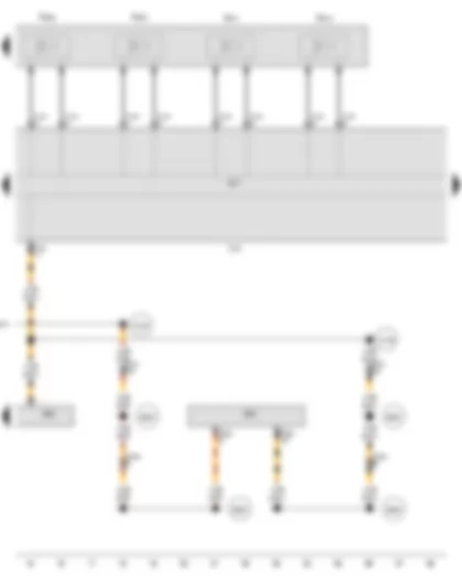
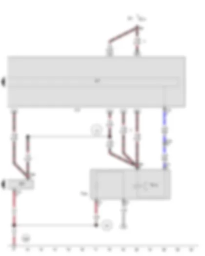
Wiring Diagram AUDI A5 CABRIOLET 2009 - Automatic gearbox control unit - Convenience system central control unit - Valve 3 in sub-gearbox 1 - Valve 4 in sub-gearbox 1
| J217 | Automatic gearbox control unit |
| J393 | Convenience system central control unit |
| J623 | Engine control unit |
| J743 | Mechatronic unit for dual clutch gearbox |
| N435 | Valve 3 in sub-gearbox 1 |
| N436 | Valve 4 in sub-gearbox 1 |
| SB1 | Fuse 1 on fuse holder B |
| ST1 | Fuse carrier 1 |
| SB12 | Fuse 12 on fuse holder B |
| T14h | 14-pin connector |
| T16r | 16-pin connector |
| T17q | 17-pin connector, red |
| T32d | 32-pin connector |
| 85 | Earth connection 1, in engine compartment wiring harness |
| 131 | Earth connection 2, in engine compartment wiring harness |
| 132 | Earth connection 3, in engine compartment wiring harness |
| D112 | Connection 10 in engine compartment wiring harness |
| D114 | Connection 12 in engine compartment wiring harness |
| D160 | Connection (low bus), in engine compartment wiring harness |
| * | see applicable current flow diagram for engine |
| *2 | see applicable current flow diagram for fuse assignment |
| *3 | Only models with diesel engines |
| *4 | Gradually discontinued |
| *5 | Cross section depends on equipment |
| *6 | Cross-section 1.5 possible |
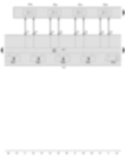
Wiring Diagram AUDI A5 CABRIOLET 2009 - Automatic gearbox control unit - Data bus diagnostic interface - Valve 3 in sub-gearbox 2 - Valve 4 in sub-gearbox 2 - Cooling oil valve - Main pressure valve
| J217 | Automatic gearbox control unit |
| J533 | Data bus diagnostic interface |
| J623 | Engine control unit |
| J743 | Mechatronic unit for dual clutch gearbox |
| N439 | Valve 3 in sub-gearbox 2 |
| N440 | Valve 4 in sub-gearbox 2 |
| N471 | Cooling oil valve |
| N472 | Main pressure valve |
| T14h | 14-pin connector |
| T16r | 16-pin connector |
| T17b | 17-pin connector, blue |
| T17r | 17-pin connector, white |
| T20d | 20-pin connector |
| B383 | Connection 1 (powertrain CAN bus, high), in main wiring harness |
| B385 | Connection 3 (powertrain CAN bus, high), in main wiring harness |
| B390 | Connection 1 (powertrain CAN bus, low), in main wiring harness |
| B392 | Connection 3 (powertrain CAN bus, low), in main wiring harness |
| D159 | Connection (high bus), in engine compartment wiring harness |
| D160 | Connection (low bus), in engine compartment wiring harness |
| * | see applicable current flow diagram for engine |
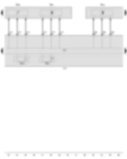
Wiring Diagram AUDI A5 CABRIOLET 2009 - Automatic gearbox hydraulic pressure sender 1 - Gear selector movement sensor 1 - Gear selector movement sensor 2 - Gear selector movement sensor 3 - Gear selector movement sensor 4 - Automatic gearbox control unit
| G193 | Automatic gearbox hydraulic pressure sender 1 |
| G487 | Gear selector movement sensor 1 |
| G488 | Gear selector movement sensor 2 |
| G489 | Gear selector movement sensor 3 |
| G490 | Gear selector movement sensor 4 |
| J217 | Automatic gearbox control unit |
| J743 | Mechatronic unit for dual clutch gearbox |
| N433 | Valve 1 in sub-gearbox 1 |
| N434 | Valve 2 in sub-gearbox 1 |
| N437 | Valve 1 in sub-gearbox 2 |
| N438 | Valve 2 in sub-gearbox 2 |
| T14i | 14-pin connector |
Wiring Diagram AUDI A5 CABRIOLET 2009 - Automatic gearbox hydraulic pressure sender 2 - Temperature sender in control unit - Gearbox input speed sender 2 - Automatic gearbox control unit
| G194 | Automatic gearbox hydraulic pressure sender 2 |
| G509 | Clutch temperature sender |
| G510 | Temperature sender in control unit |
| G612 | Gearbox input speed sender 2 |
| G641 | Gearbox input speed sender 3 |
| J217 | Automatic gearbox control unit |
| J743 | Mechatronic unit for dual clutch gearbox |
| T8al | 8-pin connector |
| T14i | 14-pin connector |
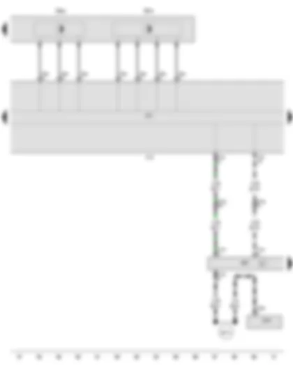
Wiring Diagram AUDI A5 CABRIOLET 2009 - Gearbox input speed sender 1 - Gear sensor - Automatic gearbox control unit - Onboard supply control unit - Selector lever sensors control unit
| G632 | Gearbox input speed sender 1 |
| G676 | Gear sensor |
| J217 | Automatic gearbox control unit |
| J519 | Onboard supply control unit |
| J587 | Selector lever sensors control unit |
| J743 | Mechatronic unit for dual clutch gearbox |
| T8al | 8-pin connector |
| T10k | 10-pin connector |
| T16r | 16-pin connector |
| T17q | 17-pin connector, red |
| T32b | 32-pin connector |
| B472 | Connection 8, in main wiring harness |
Wiring Diagram AUDI A5 CABRIOLET 2009 - Gear selector position P switch - Automatic gearbox control unit - Selector lever sensors control unit - Selector lever lock solenoid
| F305 | Gear selector position P switch |
| J217 | Automatic gearbox control unit |
| J587 | Selector lever sensors control unit |
| J743 | Mechatronic unit for dual clutch gearbox |
| N110 | Selector lever lock solenoid |
| ST1 | Fuse carrier 1 |
| SC10 | Fuse 10 on fuse holder C |
| T4h | 4-pin connector |
| T10k | 10-pin connector |
| T16r | 16-pin connector |
| T17q | 17-pin connector, red |
| 367 | Earth connection 2, in main wiring harness |
| U2 | Connection 1 (15) in automatic gearbox wiring harness |
| * | Gradually discontinued |
| *2 | see applicable current flow diagram for fuse assignment |
| *3 | gradual introduction |
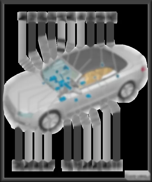
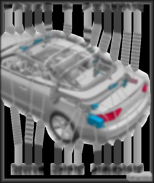
AUDI A5 CABRIOLET 2009 Overview of control units
| q | Location and connector, from model year 2013: |
| q | Location and connectors for models with 800 W or 1000 W radiator fan: |
| 2 - | Radiator fan control unit 2 -J671- / radiator fan 2 -V177- |
| q | Location and connectors for models with 800 W or 1000 W radiator fan: |
| q | Location and connectors for models with right-hand drive (with -T60- and -T94-): |
| q | Location and connectors for models with left-hand drive -T91- and -T105-): |
| q | Location and connectors for models with right-hand drive (with -T91- and -T105-): |
| q | Location and connector, from model year 2013: |
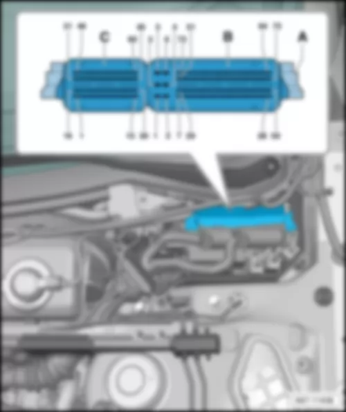
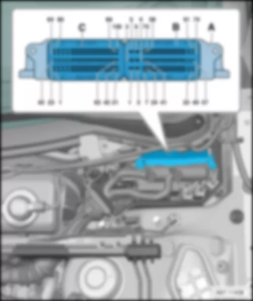
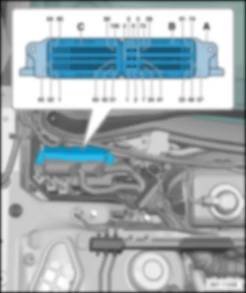
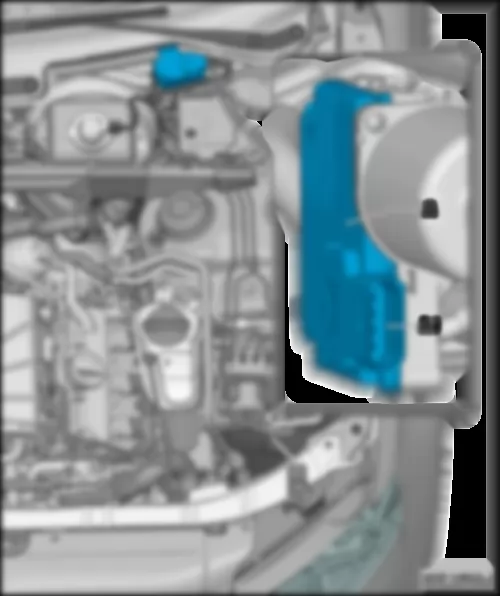
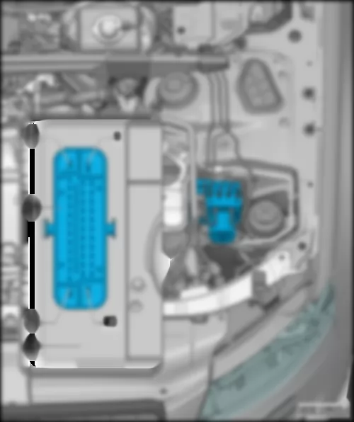
| A - | Engine control unit -J623- |
| C - | 60-pin connector, on wiring harness -T60- |
| |
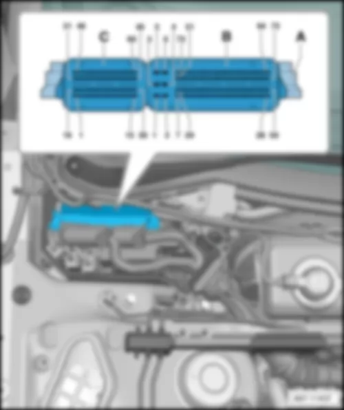
| A - | Engine control unit -J623- |
| B - | 94-pin connector -T94- |
| C - | 60-pin connector -T60- |
Note:
|
| A - | Engine control unit -J623- |
| C - | 105-pin connector -T105- |
Note:
|
| A - | Engine control unit -J623- |
| B - | 91-pin connector -T91- |
| C - | 105-pin connector -T105- |
|
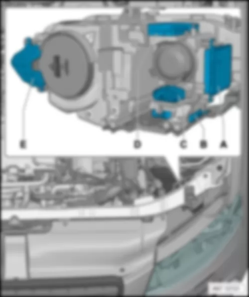
| C - | Power output module for left headlight -J667- |
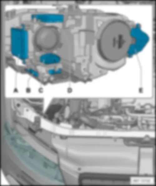
AUDI A5 CABRIOLET 2009 Right gas discharge light control unit J344 , up to model year 2012 | Right gas discharge light control unit -J344-, up to model year 2012 |
| Location: |
| on right headlight. |
| C - | Power output module for right headlight -J668- |
AUDI A5 CABRIOLET 2009 Left gas discharge light control unit J343 , from model year 2013 | Left gas discharge light control unit -J343-, from model year 2013 |
| Location: |
| on left headlight. |
| A - | Left gas discharge light control unit -J343- |
| B - | Control unit for left daytime running light and side light -J860-, Left LED module for daytime running light and side light -L176- |
| C - | 14-pin connector -T14a- |
| D - | Power output module for left headlight -J667- |
| E - | Output module for left side marker light -J986- |
|
| A - | Right gas discharge light control unit -J344- |
| B - | Control unit for right daytime running light and side light -J861-, Right LED module for daytime running light and side light -L177- |
| C - | 14-pin connector -T14b- |
| D - | Power output module for right headlight -J668- |
| E - | Output module for right side marker light -J987- |
|
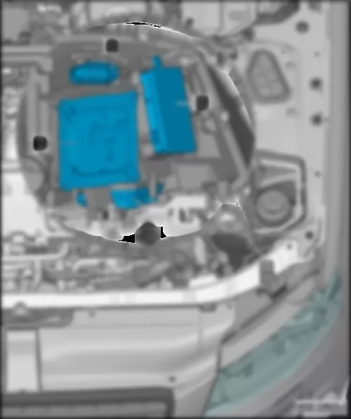
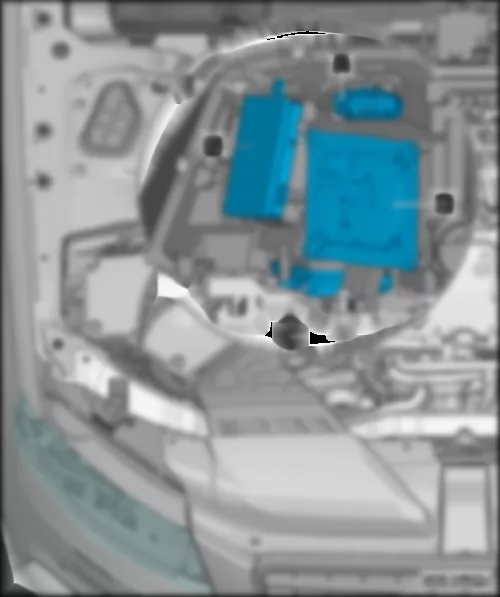
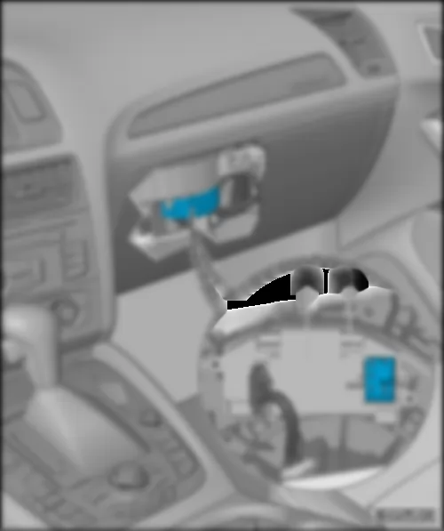
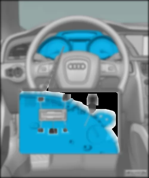
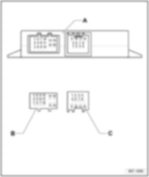
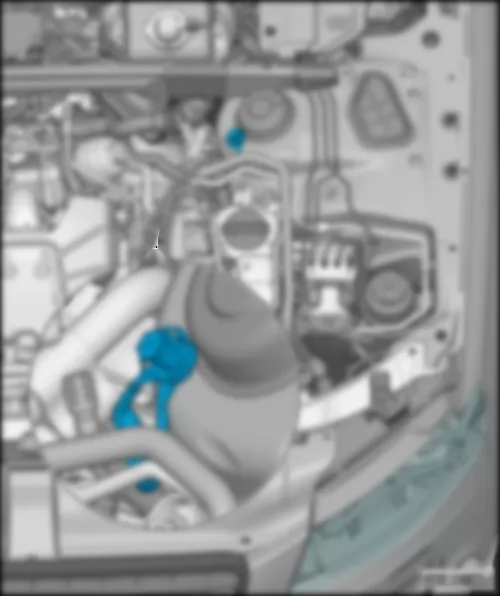
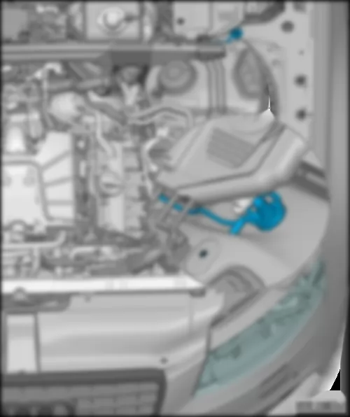
| A - | Automatic gearbox control unit -J217- / Mechatronics for dual clutch gearbox -J743- |
| A2 - | 8-pin connector -T8al- |
| A4 - | 14-pin connector -T14i- |
|
| A - | Wiper motor control unit -J400- |
AUDI A5 CABRIOLET 2009 ABS control unit J104 | ABS control unit -J104- |
| Location: |
| in left of engine compartment. |
| A - | ABS control unit -J104- |
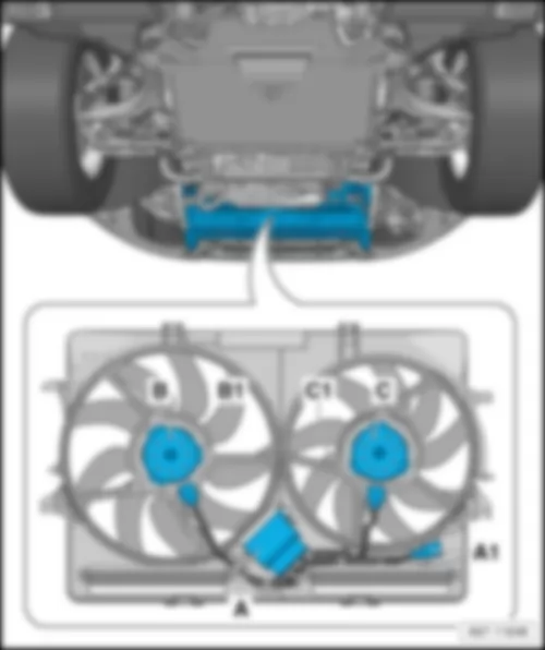
AUDI A5 CABRIOLET 2009 400 W or 600 W radiator fan | 400 W or 600 W radiator fan |
| Location: |
| on radiator. |
Note:
| Radiator fan 2 -V177- present depending on engine variant. |
| A - | Radiator fan control unit -J293- |
| B1 - | 2-pin connector, black -T2kl- |
| C - | Radiator fan 2 -V177- |
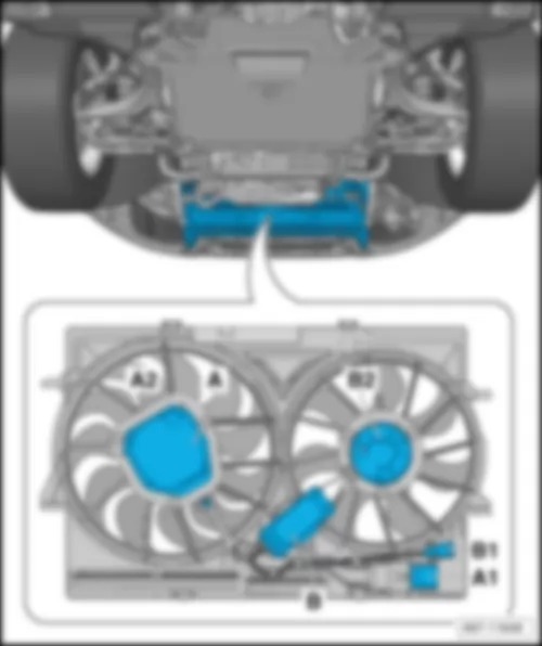
AUDI A5 CABRIOLET 2009 800 W or 1000 W radiator fan | 800 W or 1000 W radiator fan |
| Location: |
| on radiator. |
| A - | Radiator fan control unit -J293- |
| B1 - | 4-pin connector -T4bl- |
| B2 - | Radiator fan 2 -V177- |
|
| A - | Garage door operation control unit -J530- |
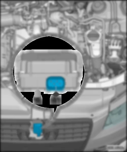
AUDI A5 CABRIOLET 2009 Adaptive​ cruise​ control​ unit J428 | Adaptive cruise control unit -J428- |
| Location: |
| In front bumper grill cover on right. |
| A - | Adaptive cruise control unit -J428- |
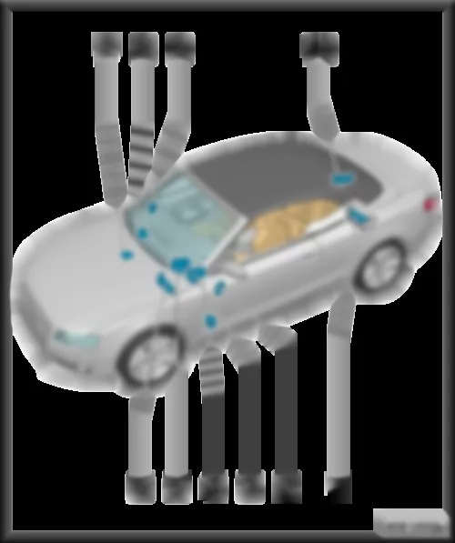
AUDI A5 CABRIOLET 2009 Overview of control units in interior of vehicle | Overview of control units in interior of vehicle |
| q | for models without MMI: |
| q | Connectors: |
| 8 - | Multimedia system operating unit -E380- |
| q | Fitting location and connector: |
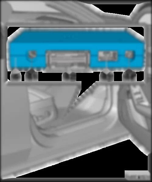
| 10 - | Rear left door control unit -J388- |
| q | Fitting location and connectors: |
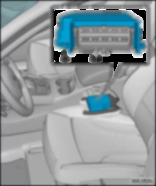
| 12 - | Airbag control unit -J234- |
| q | Fitting location and connector: |
| 13 - | Active steering control unit -J792- |
| q | Fitting location and connectors: |
| q | Connectors: |
| q | Fitting location and connectors for models with right-hand drive: |
| 17 - | Control unit for electronic steering column lock -J764- |
| q | Location: on steering column |
| 18 - | Climatronic control unit -J255- |
| q | Fitting location and connectors: |
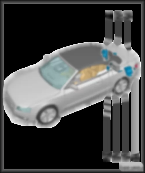
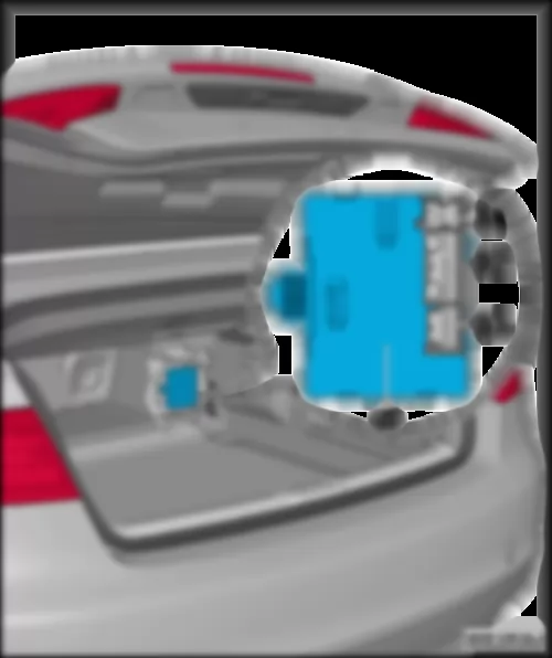
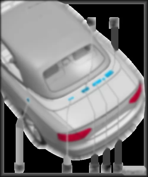
| Overview of control units in rear part of vehicle |
| 1 - | Electronically controlled damping control unit -J250- |
| q | Location: in right of luggage compartment, behind side trim |
| q | Connector: |
| 1 - | Trailer detector control unit -J345- |
| q | Location: in right of luggage compartment, behind side trim |
| q | Connectors: |
| 2 - | Lane change assist control unit -J769- |
| q | Location: on inside of rear bumper |
| 3 - | Satellite radio -R146- |
| q | Location: in left of luggage compartment, behind side trim. |
|
|
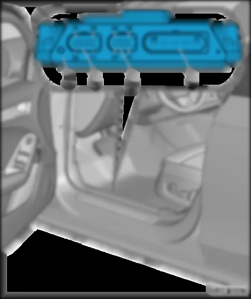
| Connectors on driver door control unit -J386- |
| B - | 20-pin connector -T20f- |
| D - | 32-pin connector -T32j- |
| Connectors on front passenger door control unit -J387- |
| B - | 20-pin connector -T20g- |
| D - | 32-pin connector -T32l- |
|
| A - | Rear left door control unit -J388- |
| A2 - | 20-pin connector -T20h- |
| A3 - | Not assigned |
|
| A - | Rear right door control unit -J389- |
| A2 - | 20-pin connector -T20i- |
| A3 - | Not assigned |
|
| Rain and light detector sensor -G397- |
| 4 - | Main beam assist control unit -J844- |
Note
|
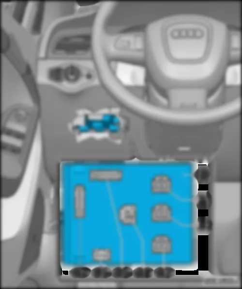
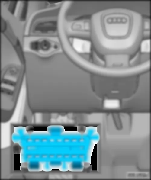
| A - | Onboard supply control unit -J519- |
| A2 - | 17-pin connector, brown (connector E) -T17m- |
| A4 - | 6-pin connector, green (connector G) -T6f- |
| A6 - | 16-pin connector, brown (connector C) -T16b- |
| Location onboard supply control unit -J519- for models with right-hand drive: |
| Driver side dash panel, bottom. |
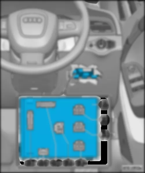
Note
| t | Figure shows right-hand drive model. |
| t | Figure for left-hand drive models . |
| A - | Onboard supply control unit -J519- |
| A1 - | 17-pin connector, black (connector D) -T17l- |
| A2 - | 17-pin connector, brown (connector E) -T17m- |
| A3 - | 17-pin connector, red (connector F) -T17n- |
| A4 - | 6-pin connector, green (connector G) -T6f- |
| A5 - | 32-pin connector, grey (connector A) -T32a- |
| A6 - | 16-pin connector, brown (connector C) -T16b- |
| A7 - | 32-pin connector, black (connector B) -T32b- |
|
| 4 - | Active steering control unit -J792- |
| Connectors: |
| 2 - | 8-pin connector, black -T8g- |
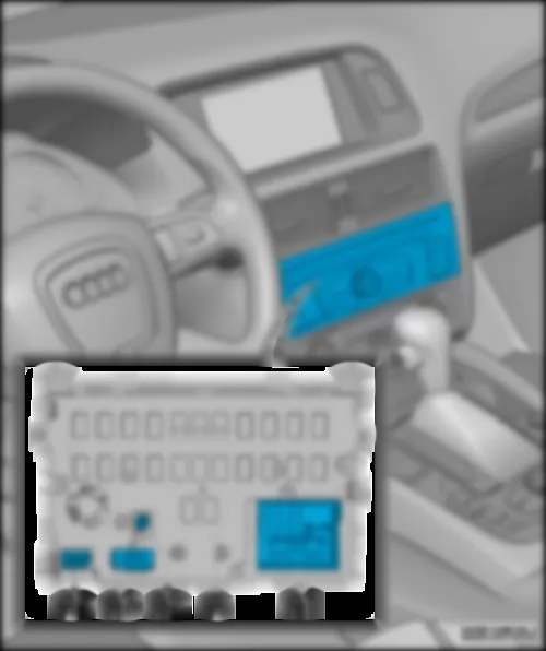
AUDI A5 CABRIOLET 2009 Radio R (with integrated CD changer R41 / DVD changer R161 ) | Radio -R- (with integrated CD changer -R41- / DVD changer -R161-) |
| Fitting location: |
| in dash panel centre section. |
| A - | Radio -R- |
| A1 - | Connector block, consisting of: |
| t | 8-pin connector, brown -T8k- |
| t | 8-pin connector, black -T16l- |
| t | 12-pin connector, green -T12a- |
| t | 12-pin connector, blue -T12s- |
| 1-pin connector, black -T1i- (DAB connection) / 1-pin connector, green -T1k- (SDARS connection) |
| A4 - | 2-pin connector, white -T2df- (AM / FM1 / FM2 connection) |
|
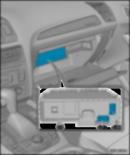
| A - | CD changer -R41- / DVD changer -R161- |
| A1 - | 8-pin connector -T8aa- |
| A2 - | 2-pin connector -T2dm- |
Note
|
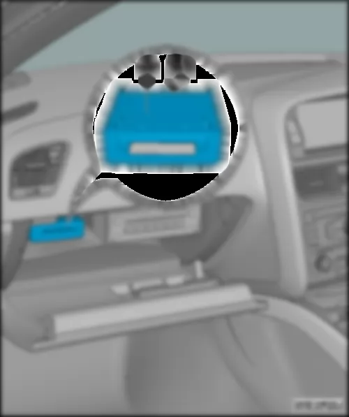
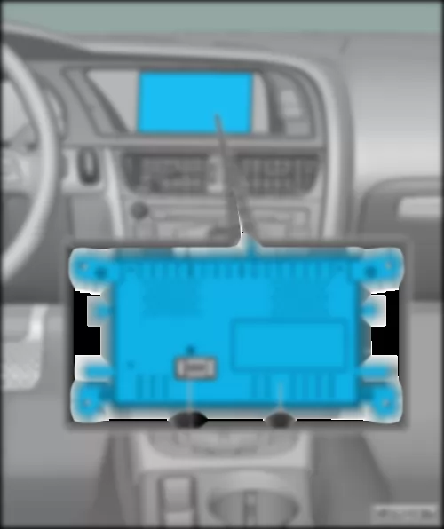
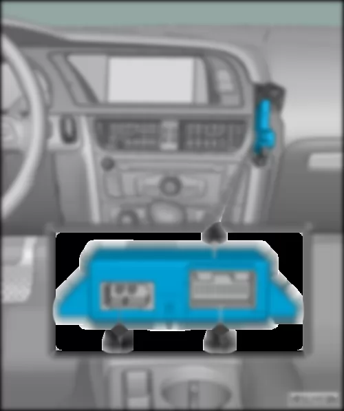
| A - | Chip card reader control unit -J676- |
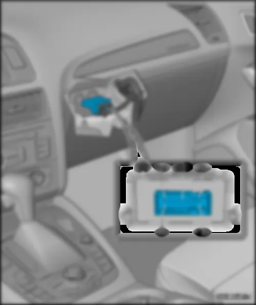
AUDI A5 CABRIOLET 2009 Display unit for front information display and operating unit control unit J685 | Display unit for front information display and operating unit control unit -J685- |
| Fitting location: |
| Dash panel - centre. |
Note
| Connector -A1- is given as an example for differing equipment versions |
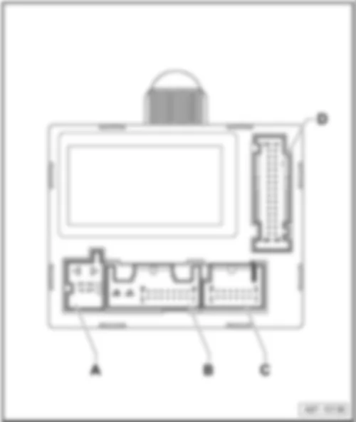
| A - | Display unit for front information display and operating unit control unit -J685- |
| A1 - | Connector for models with MMI High up to August 2009: |
| t | 22-pin connector, black -T22b- |
| A1 - | Connectors for models with MMI Basic, from September 2009: |
| t | 8-pin connector, black -T8ai- |
| t | 4-pin connector, white -T4ao- |
| A1 - | Connectors for models with MMI High from September 2009: |
| t | 8-pin connector, black -T8ai- |
| t | 4-pin connector, black -T4an- |
| A1 - | 10-pin connector, red -T10u- |
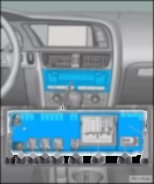
| A1 - | AUDI A5 CABRIOLET 2009 Control unit 1 for information electronics J794 | Control unit 1 for information electronics -J794- |
| Fitting location: |
| in dash panel centre section. |
| A - | Control unit 1 for information electronics -J794- |
| A2 - | 1-pin connector, blue -T1n- |
| A3 - | Not assigned |
| A5 - | for models with -J794- basic: |
| t | 4-pin connector, violet -T4al- |
| A6 - | 1-pin connector, green -T1o- |
| A7 - | Connector block, consisting of: |
| t | 8-pin connector, brown -T8ah- |
| t | 8-pin connector, black -T8ao- |
| t | 12-pin connector, blue -T12x- |
| t | 12-pin connector, green -T12y- |
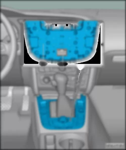
AUDI A5 CABRIOLET 2009 Multimedia system operating unit E380 | Multimedia system operating unit -E380- |
| Fitting location: |
| on centre console. |
| A - | Multimedia system operating unit -E380- |
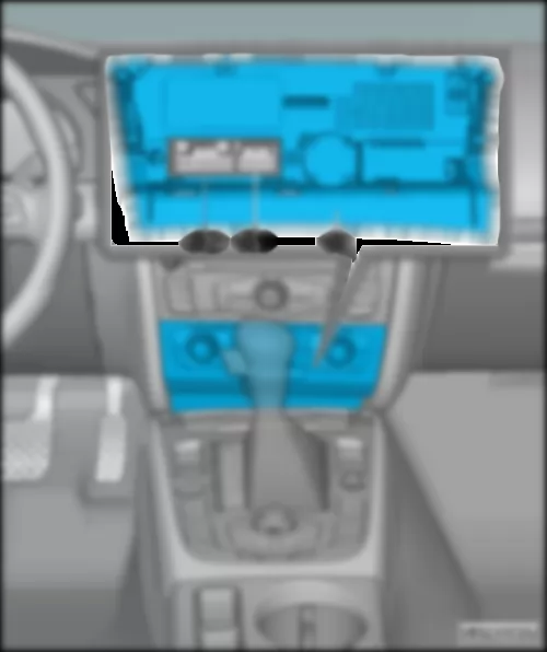
AUDI A5 CABRIOLET 2009 Climatronic control unit J255 | Climatronic control unit -J255- |
| Fitting location: |
| in dash panel centre section. |
| A - | Climatronic control unit -J255- |
| A2 - | 20-pin connector -T20e- |
|
| A - | Airbag control unit -J234- |
AUDI A5 CABRIOLET 2009 Telephone transmitter and receiver unit R36 | Telephone transmitter and receiver unit -R36- |
| Fitting location: |
| in front right footwell. |
| A - | Telephone transmitter and receiver unit -R36- |
| A1 - | Connector -B- (Aerial for Bluetooth) |
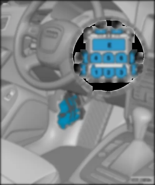
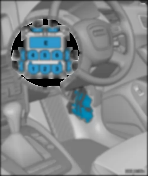
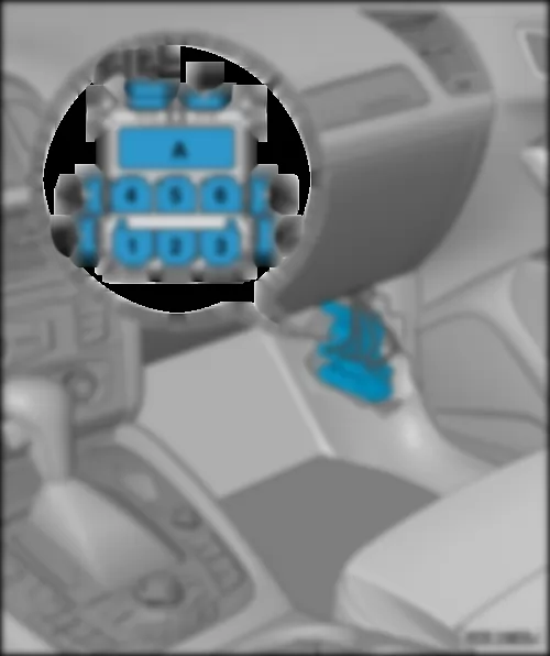
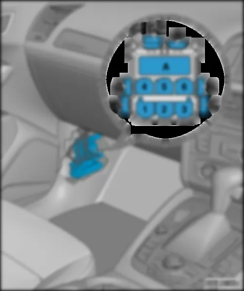
AUDI A5 CABRIOLET 2009 16-pin connector T16 , diagnostic connection | 16-pin connector -T16-, diagnostic connection |
| Fitting location: |
| Driver side dash panel, bottom. |
| A - | 16-pin connector -T16-, diagnostic connection |
|
| A - | Data bus diagnostic interface -J533- |
| A2 - | 20-pin connector -T20d- |
|
| A - | Control unit in dash panel insert -J285- |
AUDI A5 CABRIOLET 2009 Connectors on convenience system central control unit J393 | Connectors on convenience system central control unit -J393- |
| 2 - | 32-pin connector, black (connector B) -T32c- |
| 4 - | 32-pin connector, blue (connector F) -T32e- |
| 5 - | 6-pin connector (connector G) -nicht belegt- |
| 7 - | 1-pin connector, grey (connector D) -T1h- |
| Connectors on electronically controlled damping control unit -J250- |
| A - | Electronically controlled damping control unit -J250- |
| Connector: |
AUDI A5 CABRIOLET 2009 Connectors on trailer detector control unit J345 | Connectors on trailer detector control unit -J345- |
| A - | Trailer detector control unit -J345- |
| Connectors: |
| C - | 12-pin connector, red -T12d- |
| Connectors on park assist steering control unit -J791- |
| B - | 12-pin connector, brown -T12e- |
AUDI A5 CABRIOLET 2009 All-wheel drive control unit J492 | All-wheel drive control unit -J492- |
| Fitting location: |
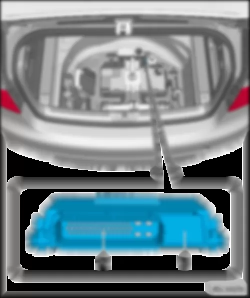
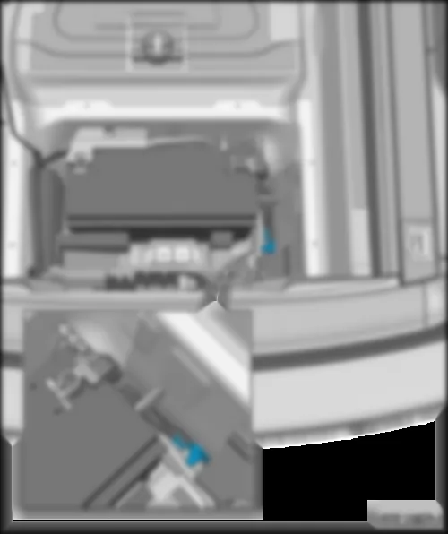
| In spare wheel recess, in front of battery |
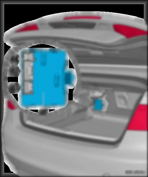
| 1 - | All-wheel drive control unit -J492- |
AUDI A5 CABRIOLET 2009 Voltage stabiliser J532 | Voltage stabiliser -J532- |
| Fitting location: |
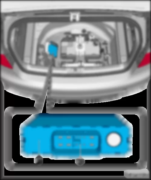
| In spare wheel recess, on left next to battery. |
| 1 - | Voltage stabiliser -J532- |
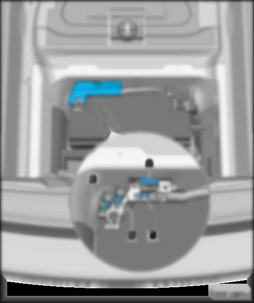
AUDI A5 CABRIOLET 2009 Battery monitoring control unit J367 | Battery monitoring control unit -J367- |
| Fitting location: |
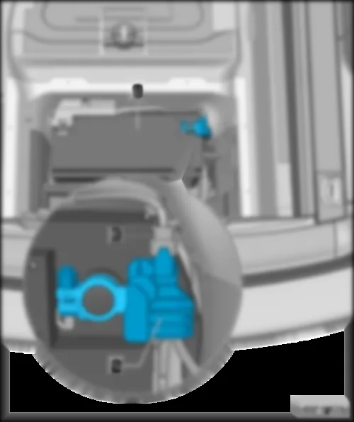
| on negative terminal of battery -A-. |
| 3 - | 2-pin connector -T2x- |
| Overview of convertible roof components |
| 12 - | Convertible roof actuation control unit -J256- |
| q | Fitting location: |
| 16 - | Left motor for convertible roof box -V433- |
| q | Fitting location: |
| Convertible roof actuation button -E137- / Central switch for window regulators -E643- |
| q | Fitting location: |
|
|
|
|
|
|
|
|
|
|
|
|
|
|
|
|
|
|
|
|
|
|
|
|
| Overview of aerial amplifiers |
| 1 - | Aerial amplifier 4 -R113- |
| 2 - | Telephone aerial -R65- |
| 4 - | Aerial amplifier -R24- |
| 6 - | Satellite aerial -R170- |
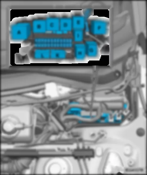
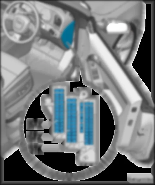
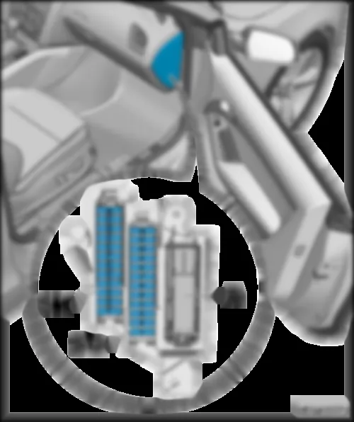
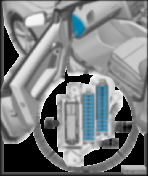
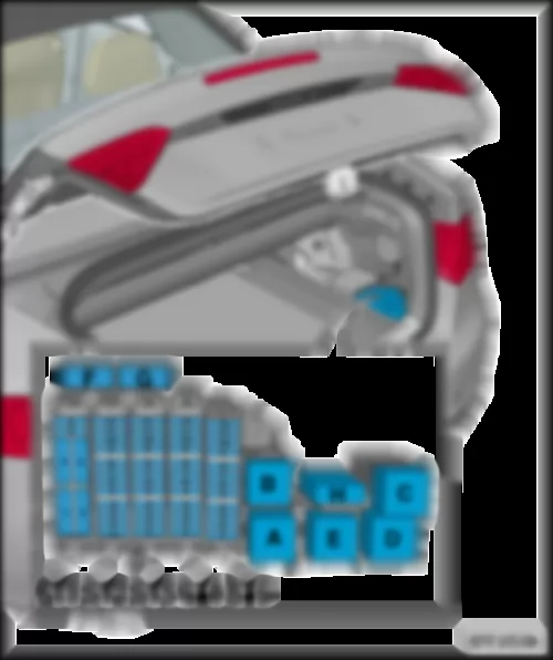
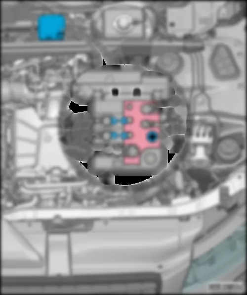
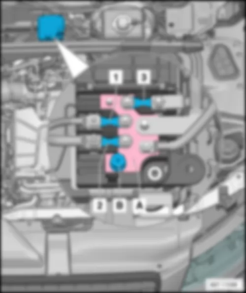
AUDI A5 CABRIOLET 2009 Overview of fuses | Overview of fuses |
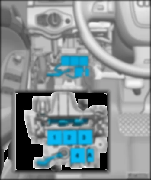
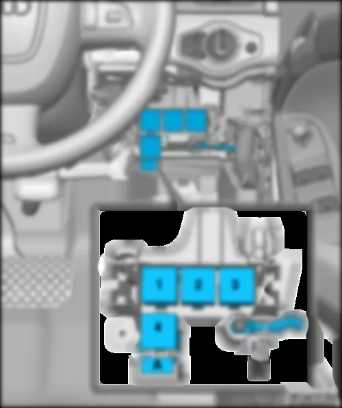
| Fuse holder A -SA- |
| q | Fitting location: |
| q | Location for models with right-hand drive only, up to July 2011: |
| q | Location for models with left-hand drive only, from August 2011: |
| q | Location for models with right-hand drive only, from August 2011: |
| q | Fitting location for models with right-hand drive: |
| 6-pin coupling station of A-pillar, driver side |
| q | Fitting location for models with left-hand drive: |
| q | Fitting location for models with right-hand drive: |
| 3-pin relay and fuse holder |
| q | Fitting location for models with left-hand drive: |
| q | Fitting location for models with right-hand drive: |
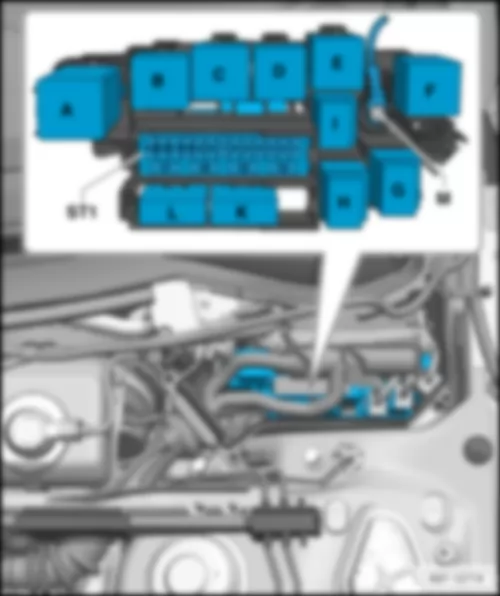
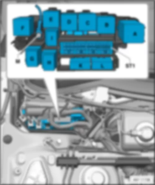
| Relay/fuse holder B -SB- |
| q | Location for models with left-hand drive only, up to July 2011: |
| q | Location for models with right-hand drive only, up to July 2011: |
| q | Location for models with left-hand drive only, from August 2011: |
| q | Location for models with right-hand drive only, from August 2011: |
| q | Location for models from August 2011: |
| 6-pin coupling station of A-pillar, front passenger side |
| q | Fitting location for models with left-hand drive: |
| q | Fitting location for models with right-hand drive: |
| q | Fitting location for models with right-hand drive: |
| Relay/fuse holder F -SF- |
| q | Location for models up to July 2011: |
| q | Location for models from August 2011: |
|
| A - | Battery isolation igniter -N253- |
| 1 - | Fuse 1 on fuse holder A -SA1-, |
| 2 - | Fuse 2 on fuse holder A -SA2-, |
| 3 - | Fuse 3 on fuse holder A -SA3-, |
Note
|
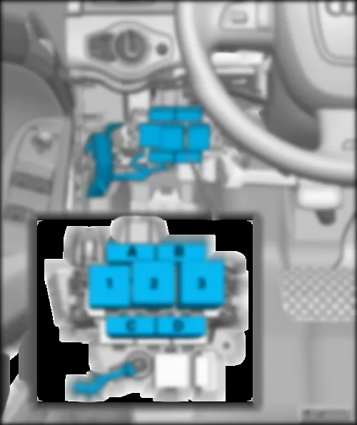
| ST1 - | Fuse carrier 1, fuses |
| ST2 - | Fuse carrier 2, fuses |
| A - | 46-pin connector, black, CAN disconnector, dash panel -T46s- |
|
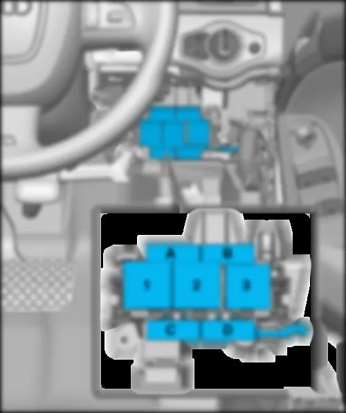
| ST1 - | Fuse carrier 1, fuses |
| ST2 - | Fuse carrier 2, fuses |
| A - | 46-pin connector, black, CAN disconnector, dash panel -T46s- |
|
| No. | Current Flow Diagram designation | Nominal value | Function/component | Terminal | ||
| 1 | - | Fuse 1 on fuse holder D -SD1- | - | Not assigned | ||
| 2 | - | Fuse 2 on fuse holder D -SD2- | - | Not assigned | ||
| 3 | - | Fuse 3 on fuse holder D -SD3- | - | Not assigned | ||
| 4 | - | Fuse 4 on fuse holder D -SD4- | - | Not assigned | ||
| 5 | - | Fuse 5 on fuse holder D -SD5- | 5 A | - | Steering column electronics control unit -J527- | 15 |
| 6 | - | Fuse 6 on fuse holder D -SD6- | 5 A | - | TCS and ESP button -E256- Parking aid button -E266- | 15 |
| 7 | - | Fuse 7 on fuse holder D -SD7- | 5 A | - | 16-pin connector -T16-, diagnostic connector | 15 |
| 8 | - | Fuse 8 on fuse holder D -SD8- | 5 A | - | Data bus diagnostic interface -J533- | 15 |
| 9 | - | Fuse 9 on fuse holder D -SD9- | 5A | - | High heat output relay -J360- | 15 |
| 10 | - | Fuse 10 on fuse holder D -SD10- | - | Not assigned | ||
| 11 | - | Fuse 11 on fuse holder D -SD11- | - | Not assigned | ||
| 12 | - | Fuse 12 on fuse holder D -SD12- | - | Not assigned |
|
| No. | Current Flow Diagram designation | Nominal value | Function/component | Terminal | ||
| 1 | - | Fuse 1 on fuse holder D -SD1- | 5 A | - | CD changer -R41- DVD changer -R161- Connection for external audio sources -R199- | 30 |
| 2 | - | Fuse 2 on fuse holder D -SD2- | 5 A | - | Switch module for driving mode selection -E592- | 30 |
| 3 | - | Fuse 3 on fuse holder D -SD3- | 5 A 5 A 20 A 20 A | - | Display unit for front information display and operating unit control unit -J685- Control unit 1 for information electronics -J794- Radio -R- | 30 |
| 4 | - | Fuse 4 on fuse holder D -SD4- | 5 A | - | Control unit in dash panel insert -J285- | 30 |
| 5 | - | Fuse 5 on fuse holder D -SD5- | 5 A | - | Data bus diagnostic interface -J533- | 30 |
| 6 | - | Fuse 6 on fuse holder D -SD6- | 5 A | - | Entry and start authorisation switch -E415- | 30 |
| 7 | - | Fuse 7 on fuse holder D -SD7- | 5A | - | Light switch -E1- | |
| 8 | - | Fuse 8 on fuse holder D -SD8- | 40 A | - | Fresh air blower control unit -J126- | 30 |
| 9 | - | Fuse 9 on fuse holder D -SD9- | 5 A | - | Control unit for electronic steering column lock -J764- | 30 |
| 10 | - | Fuse 10 on fuse holder D -SD10- | 10 A | - | Climatronic control unit -J255- | 30 |
| 11 | - | Fuse 11 on fuse holder D -SD11- | 10 A | - | 16-pin connector -T16-, diagnostic connector | 30 |
| 12 | - | Fuse 12 on fuse holder D -SD12- | 5 A | - | Steering column electronics control unit -J527- | 30 |
|
| ST1 - | Fuse carrier 1, fuses |
| ST2 - | Fuse carrier 2, fuses |
| ST3 - | Fuse carrier 3, fuses |
| ST4 - | Fuse carrier 4, fuses |
| ST5 - | Fuse carrier 5, fuses |
|

