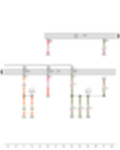
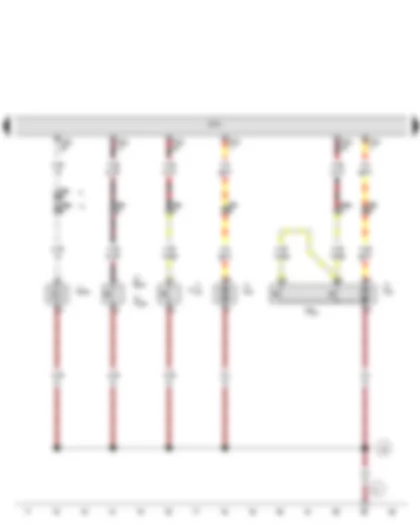
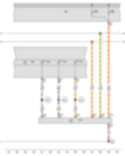
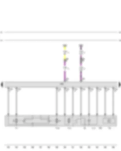
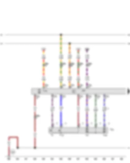
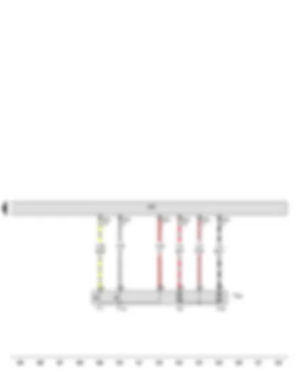
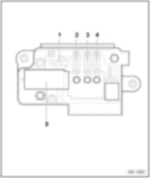
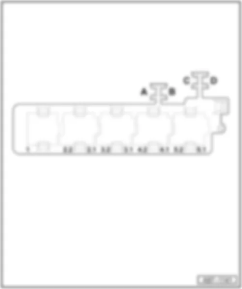
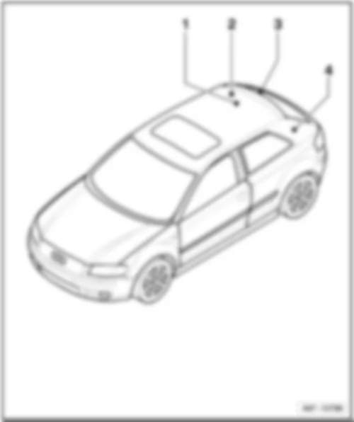
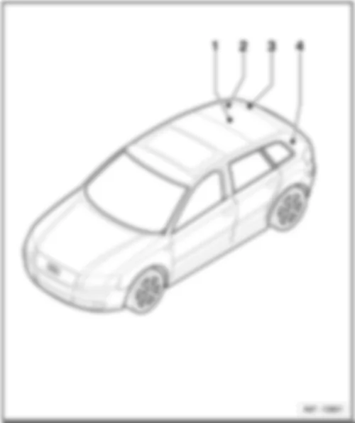
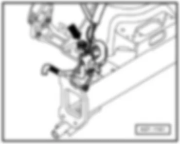
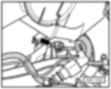
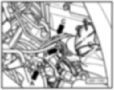
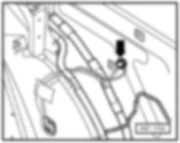
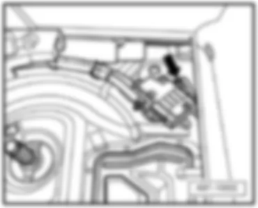
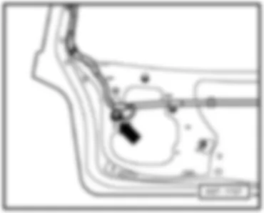
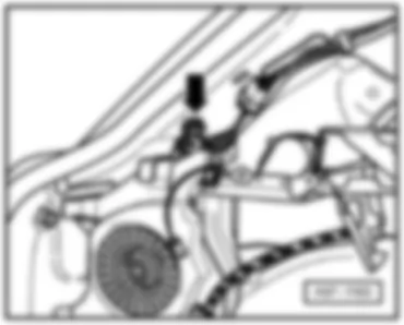
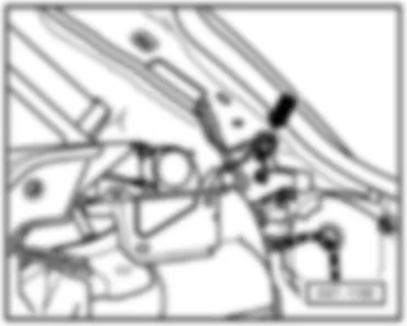
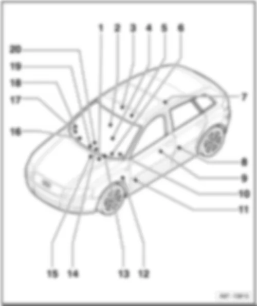
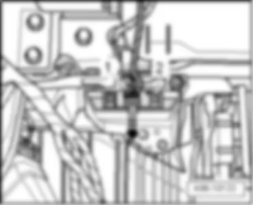
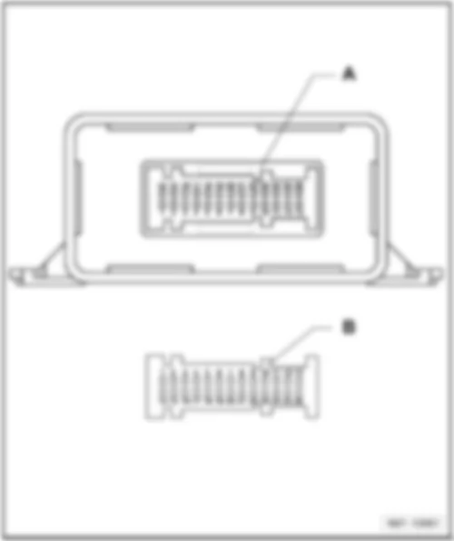
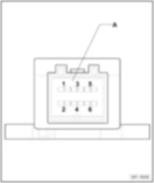
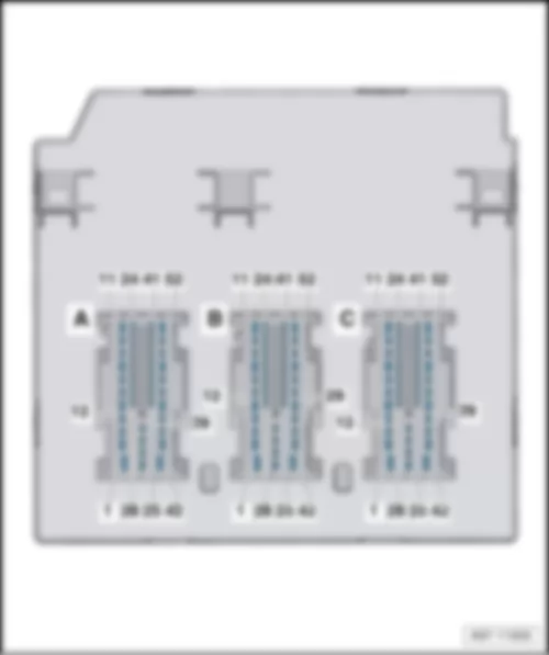
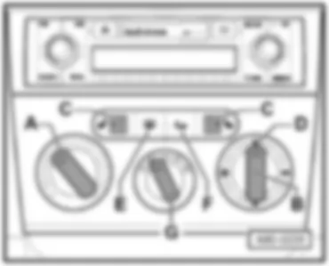
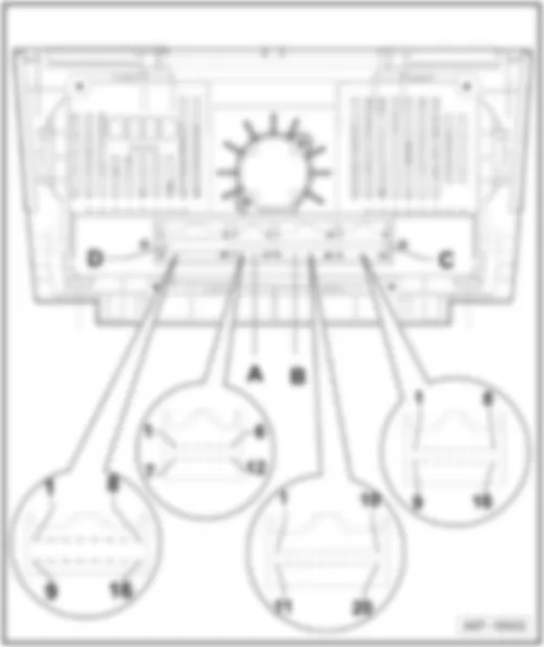
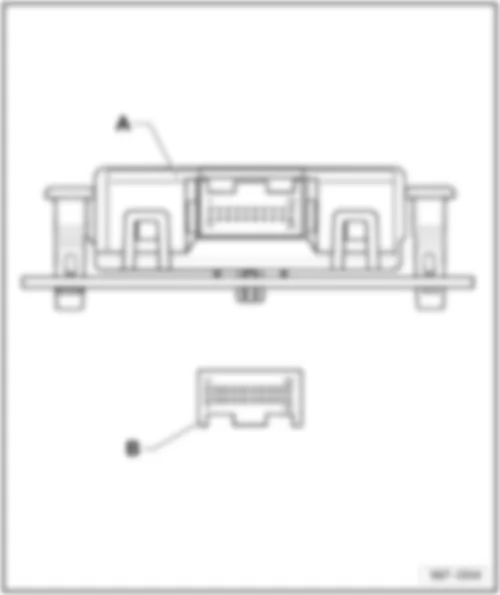
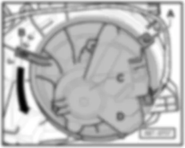
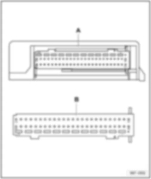
Wiring Diagram AUDI A3 2012 - Fuse holder C
| SC | Fuse holder C |
| SC12 | Fuse 12 on fuse holder C |
| SC23 | Fuse 23 on fuse holder C |
| SC28 | Fuse 28 on fuse holder C |
| SC38 | Fuse 38 on fuse holder C |
| SC43 | Fuse 43 on fuse holder C |
| B272 | Positive connection (30), in main wiring harness |
| B302 | Positive connection 6 (30), in main wiring harness |
| * | Only models with 5-doors |
| *2 | Only models with battery in luggage compartment |
| *3 | see applicable current flow diagram |
| *4 | see applicable current flow diagram for battery in engine compartment |
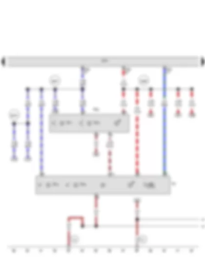
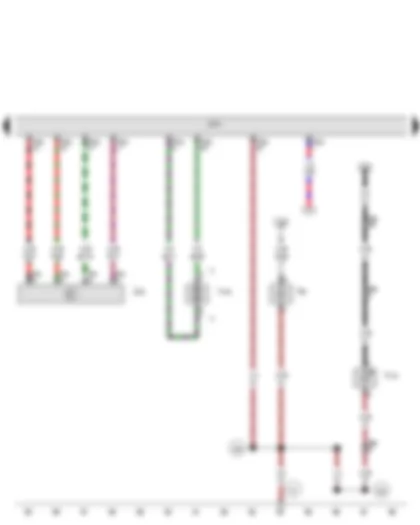
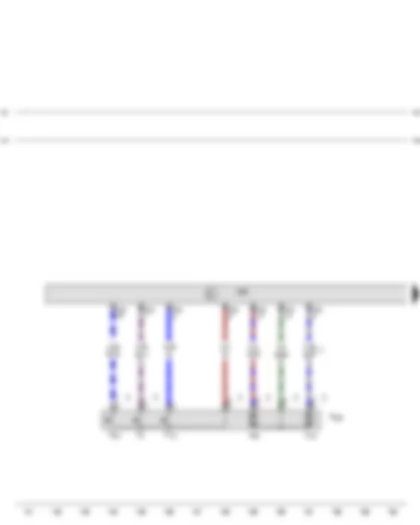
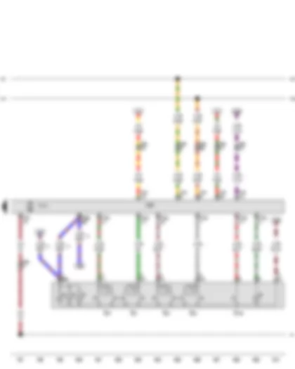
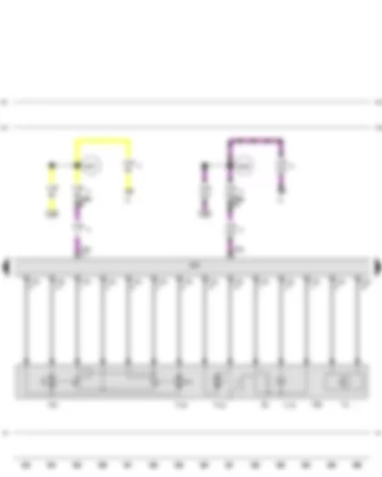
Wiring Diagram AUDI A3 2012 - Fuse holder C
| J519 | Onboard supply control unit |
| SC | Fuse holder C |
| SC13 | Fuse 13 on fuse holder C |
| SC15 | Fuse 15 on fuse holder C |
| SC17 | Fuse 17 on fuse holder C |
| T52b | 52-pin connector |
| T52c | 52-pin connector |
| B316 | Positive connection 2 (30a) in main wiring harness |
| B317 | Positive connection 3 (30a) in main wiring harness |
| * | According to equipment |
| *2 | For models with anti-theft alarm system |
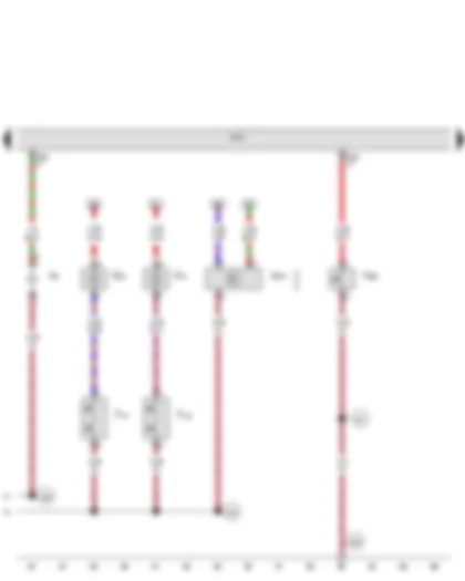
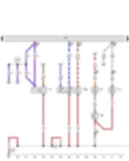
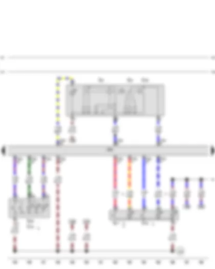
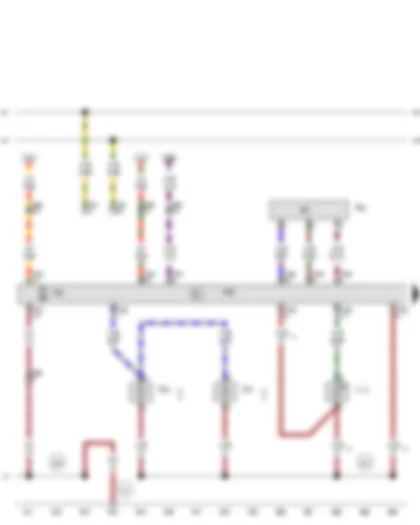
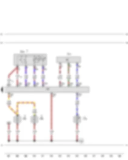
Wiring Diagram AUDI A3 2012 - Front interior light - Rear interior light
| J519 | Onboard supply control unit |
| T52b | 52-pin connector |
| T52c | 52-pin connector |
| W1 | Front interior light |
| W11 | Rear left reading light |
| W12 | Rear right reading light |
| W13 | Front passenger reading light |
| W19 | Driver side reading light |
| W43 | Rear interior light |
| 383 | Earth connection 18, in main wiring harness |
| 399 | Earth connection 34, in main wiring harness |
| B466 | Connection 2, in main wiring harness |
| B467 | Connection 3, in main wiring harness |
| B476 | Connection 12, in main wiring harness |
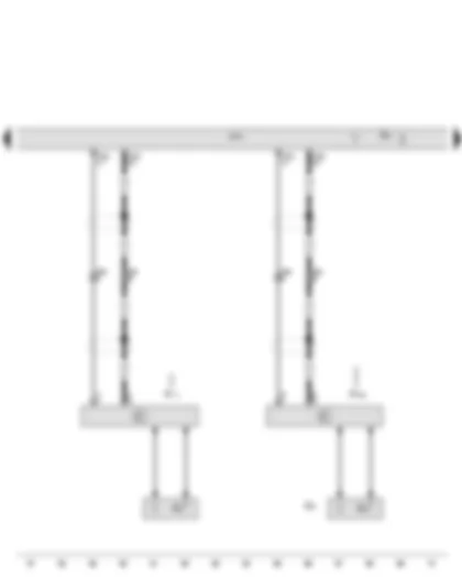
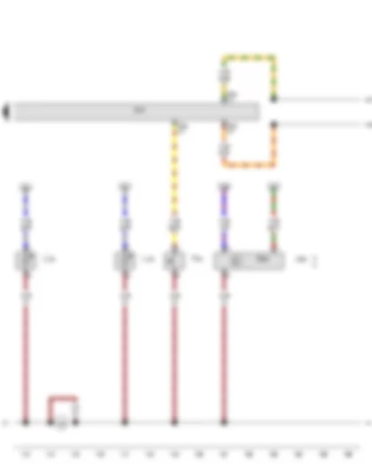
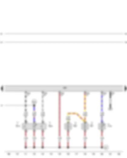
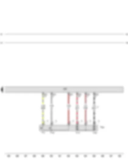
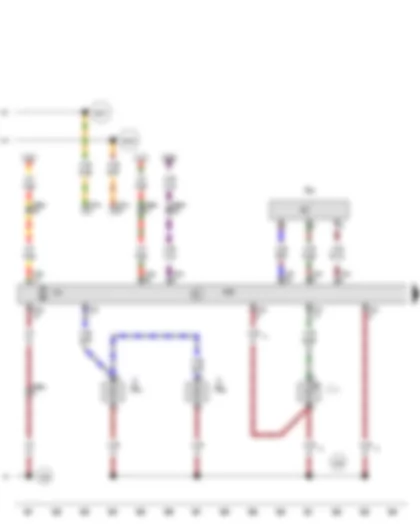
Wiring Diagram AUDI A3 2012 - Driver vanity mirror contact switch - Front passenger vanity mirror contact switch - Bonnet contact switch - Interior monitoring sensor - Luggage compartment light
| F147 | Driver vanity mirror contact switch |
| F148 | Front passenger vanity mirror contact switch |
| F266 | Bonnet contact switch |
| G273 | Interior monitoring sensor |
| J519 | Onboard supply control unit |
| T52a | 52-pin connector |
| T52b | 52-pin connector |
| W3 | Luggage compartment light |
| W14 | Front passenger side illuminated vanity mirror |
| W20 | Driver side illuminated vanity mirror |
| 381 | Earth connection 16, in main wiring harness |
| 383 | Earth connection 18, in main wiring harness |
| 399 | Earth connection 34, in main wiring harness |
| * | Only models with illuminated vanity mirror |
| *2 | Only models with interior monitoring sensor |
| *3 | Only models with no US equipment |
| *4 | For models with anti-theft alarm system |
Wiring Diagram AUDI A3 2012 - Central locking and anti-theft alarm system aerial
| J519 | Onboard supply control unit |
| R47 | Central locking and anti-theft alarm system aerial |
| R108 | Left aerial module |
| R111 | Aerial amplifier 2 |
| T2h | 2-pin connector |
| T52c | 52-pin connector |
| Z24 | Heated rear window with window aerial |
| * | Gradually discontinued |
| *2 | Only models with no radio or navigation system |
| *3 | Only for RS 3 models |
| *4 | Only models with radio navigation system |
| *5 | Only models with radio |
| *6 | gradual introduction |
| *7 | Not for RS 3 models |
Wiring Diagram AUDI A3 2012 - Rear lid handle release button - Rear lid contact switch for anti-theft alarm - Glass breakage sensor for rear window - Rear lid central locking motor
| E234 | Rear lid handle release button |
| F123 | Rear lid contact switch for anti-theft alarm |
| F248 | Release button for rear lid lock cylinder |
| G304 | Glass breakage sensor for rear window |
| J519 | Onboard supply control unit |
| T6a | 6-pin connector, on left C-pillar |
| T8ac | 8-pin connector, black |
| T8b | 8-pin connector, on left C-pillar |
| T52a | 52-pin connector |
| T52b | 52-pin connector |
| V53 | Rear lid central locking motor |
| 98 | Earth connection, in rear lid wiring harness |
| * | For models with anti-theft alarm system |
| *2 | gradual introduction |
| *3 | Gradually discontinued |
| *4 | Only models with 3-doors |
| *5 | Only models with 5-doors |
Wiring Diagram AUDI A3 2012 - Central locking deadlock function warning lamp -SAFE- - Tank filler flap locking motor - Left footwell light
| J245 | Sliding sunroof adjustment control unit |
| J519 | Onboard supply control unit |
| K133 | Central locking deadlock function warning lamp -SAFE- |
| T6b | 6-pin connector |
| T8d | 8-pin connector, behind centre console |
| T20 | 20-pin connector, on left A-pillar |
| T52a | 52-pin connector |
| T52b | 52-pin connector |
| V155 | Tank filler flap locking motor |
| W9 | Left footwell light |
| 392 | Earth connection 27, in main wiring harness |
| 393 | Earth connection 28, in main wiring harness |
| * | see applicable current flow diagram |
| *2 | Only models with US equipment |
Wiring Diagram AUDI A3 2012 - Rear central switch for interior locking - Alarm horn - Glove compartment light - Right footwell light
| E26 | Glove compartment light switch |
| E286 | Rear central switch for interior locking |
| H12 | Alarm horn |
| J519 | Onboard supply control unit |
| T8a | 8-pin connector, near glove compartment |
| T52a | 52-pin connector |
| T52b | 52-pin connector |
| W6 | Glove compartment light |
| W10 | Right footwell light |
| 388 | Earth connection 23, in main wiring harness |
| 389 | Earth connection 24, in main wiring harness |
| B528 | Connection 1 (LIN bus) in main wiring harness |
| * | Only models with alarm horn |
| *2 | Only models with US equipment |
| *3 | For models with anti-theft alarm system |
Wiring Diagram AUDI A3 2012 - Parking brake contact switch - Anti-theft and tilt system control unit - Storage compartment illumination bulb
| F321 | Parking brake contact switch |
| G384 | Vehicle inclination sender |
| J519 | Onboard supply control unit |
| J529 | Anti-theft and tilt system control unit |
| L120 | Storage compartment illumination bulb |
| T52a | 52-pin connector |
| T52c | 52-pin connector |
| 389 | Earth connection 24, in main wiring harness |
| 390 | Earth connection 25, in main wiring harness |
| B397 | Connection 1 (convenience CAN bus, high), in main wiring harness |
| B406 | Connection 1 (convenience CAN bus, low), in main wiring harness |
| * | Gradually discontinued |
| *2 | Only models with no US equipment |
| *3 | For models with anti-theft alarm system |
Wiring Diagram AUDI A3 2012 - Control unit in dash panel insert - Data bus diagnostic interface
| J285 | Control unit in dash panel insert |
| J533 | Data bus diagnostic interface |
| K102 | Rear lid closed warning lamp, |
| K166 | Door open warning lamp |
| K201 | Fuel tank flap lock warning lamp |
| SB | Fuse holder B |
| SB12 | Fuse 12 on fuse holder B |
| SB24 | Fuse 24 on fuse holder B |
| T20d | 20-pin connector |
| T32 | 32-pin connector |
| T40 | 40-pin connector |
| 390 | Earth connection 25, in main wiring harness |
| B397 | Connection 1 (convenience CAN bus, high), in main wiring harness |
| B406 | Connection 1 (convenience CAN bus, low), in main wiring harness |
| B482 | Connection 18, in main wiring harness |
| B708 | Connection 1 (dash panel insert CAN bus high) in main wiring harness |
| B709 | Connection 1 (dash panel insert CAN bus low) in main wiring harness |
| * | Gradually discontinued |
| *2 | E-box low |
| *3 | E-box high |
Wiring Diagram AUDI A3 2012 - Driver side central locking lock unit
| F2 | Driver door contact switch |
| F131 | Front left central locking actuator |
| F220 | Driver side central locking lock unit |
| F241 | Driver side contact switch in lock cylinder |
| J386 | Driver door control unit |
| T20f | 20-pin connector |
| V56 | Driver door central locking motor |
| V161 | Driver door central locking deadlock function motor |
| B397 | Connection 1 (convenience CAN bus, high), in main wiring harness |
| B406 | Connection 1 (convenience CAN bus, low), in main wiring harness |
| * | Gradually discontinued |
| *2 | gradual introduction |
| *3 | Only models with no US equipment |
Wiring Diagram AUDI A3 2012 - Mirror adjustment switch - Adjustment switch for mirror with fold-in feature - Alarm system off switch - Driver side interior locking button for central locking system
| E43 | Mirror adjustment switch |
| E48 | Mirror adjustment changeover switch |
| E150 | Driver side interior locking switch |
| E168 | Adjustment switch for mirror with fold-in feature |
| E183 | Interior monitoring switch |
| E217 | Alarm system off switch |
| E308 | Driver side interior locking button for central locking system |
| J386 | Driver door control unit |
| T32a | 32-pin connector |
| 205 | Earth connection, in driver door wiring harness |
| B397 | Connection 1 (convenience CAN bus, high), in main wiring harness |
| B406 | Connection 1 (convenience CAN bus, low), in main wiring harness |
| R52 | Connection (58s), in driver side door wiring harness |
| * | gradual introduction |
| *2 | Gradually discontinued |
| *3 | Only models with interior monitor |
| *4 | Up to April 2010 |
Wiring Diagram AUDI A3 2012 - Rear lid remote release button - Fuel tank flap release button - Driver door opener illumination bulb - Driver side door warning lamp - Front left entry light
| E233 | Rear lid remote release button |
| E319 | Fuel tank flap release button |
| J386 | Driver door control unit |
| L108 | Driver door opener illumination bulb |
| T20f | 20-pin connector |
| T32a | 32-pin connector |
| W30 | Driver side door warning lamp |
| W31 | Front left entry light |
| 267 | Earth connection 2, in drive side door wiring harness |
| B397 | Connection 1 (convenience CAN bus, high), in main wiring harness |
| B406 | Connection 1 (convenience CAN bus, low), in main wiring harness |
| R52 | Connection (58s), in driver side door wiring harness |
| * | Only models with US equipment |
| *2 | If fitted |
| *3 | Only models with no US equipment |
| *4 | Only models with illuminated door opener, entry warning lamp and door warning lamp |
| *5 | Only models with illuminated door opener on driver side |
Wiring Diagram AUDI A3 2012 - Driver side exterior mirror
| J386 | Driver door control unit |
| L131 | Driver side turn signal repeater bulb |
| T16b | 16-pin connector |
| T20 | 20-pin connector, on left A-pillar |
| T20f | 20-pin connector |
| VX4 | Driver side exterior mirror |
| V17 | Driver side mirror adjustment motor |
| V121 | Driver side fold-in mirror motor |
| V149 | Driver side mirror adjustment motor |
| Y20 | Driver side automatic anti-dazzle exterior mirror |
| Z4 | Heated exterior mirror on driver side |
| B397 | Connection 1 (convenience CAN bus, high), in main wiring harness |
| B406 | Connection 1 (convenience CAN bus, low), in main wiring harness |
| * | Only models with automatic anti-dazzle exterior mirror |
| *2 | Only models with automatic anti-dazzle interior mirror |
Wiring Diagram AUDI A3 2012 - Central switch for window regulators in driver door - Driver side window regulator motor
| E40 | Front left window regulator switch |
| E53 | Rear left window regulator switch, in driver door |
| E55 | Rear right window regulator switch, in driver door |
| E81 | Front right window regulator switch in driver door |
| E189 | Central switch for window regulators in driver door |
| J386 | Driver door control unit |
| T20 | 20-pin connector, on left A-pillar |
| T20f | 20-pin connector |
| T32a | 32-pin connector |
| V147 | Driver side window regulator motor |
| 382 | Earth connection 17, in main wiring harness |
| B397 | Connection 1 (convenience CAN bus, high), in main wiring harness |
| B406 | Connection 1 (convenience CAN bus, low), in main wiring harness |
| * | Only models with 5-doors |
| *2 | Only models with interior monitor |
| *3 | Only models with no interior monitor |
Wiring Diagram AUDI A3 2012 - Rear left window regulator switch - in door - Rear left door opener illumination bulb - Rear left window regulator motor - Rear left entry light - Rear left door warning lamp
| E52 | Rear left window regulator switch, in door |
| J388 | Rear left door control unit |
| L110 | Rear left door opener illumination bulb |
| T20l | 20-pin connector, on left B-pillar |
| T20n | 20-pin connector |
| T32e | 32-pin connector |
| V26 | Rear left window regulator motor |
| W33 | Rear left entry light |
| W37 | Rear left door warning lamp |
| 207 | Earth connection, in rear left door wiring harness |
| 382 | Earth connection 17, in main wiring harness |
| B397 | Connection 1 (convenience CAN bus, high), in main wiring harness |
| B406 | Connection 1 (convenience CAN bus, low), in main wiring harness |
| * | Only models with illuminated rear left door opener |
| *2 | According to equipment |
| *3 | Only models with no US equipment |
| *4 | Only models with no rear left door warning light and no rear left entry light |
Wiring Diagram AUDI A3 2012 - Rear left central locking lock unit
| F10 | Rear left door contact switch |
| F132 | Rear left central locking actuator |
| F222 | Rear left central locking lock unit |
| J388 | Rear left door control unit |
| T20n | 20-pin connector |
| V115 | Rear left door central locking motor |
| V163 | Rear left door central locking deadlock function motor |
| B397 | Connection 1 (convenience CAN bus, high), in main wiring harness |
| B406 | Connection 1 (convenience CAN bus, low), in main wiring harness |
| * | Gradually discontinued |
| *2 | gradual introduction |
| *3 | Only models with no US equipment |
Wiring Diagram AUDI A3 2012 - Front passenger side central locking lock unit - Front passenger side window regulator motor
| F3 | Front passenger door contact switch |
| F133 | Front right central locking actuator |
| F221 | Front passenger side central locking lock unit |
| J387 | Front passenger door control unit |
| T20a | 20-pin connector, on right A-pillar |
| T20g | 20-pin connector |
| V57 | Front passenger seat central locking motor |
| V148 | Front passenger side window regulator motor |
| V162 | Front passenger door central locking deadlock function motor |
| 386 | Earth connection 21, in main wiring harness |
| B397 | Connection 1 (convenience CAN bus, high), in main wiring harness |
| B406 | Connection 1 (convenience CAN bus, low), in main wiring harness |
| * | Gradually discontinued |
| *2 | gradual introduction |
| *3 | Only models with no US equipment |
Wiring Diagram AUDI A3 2012 - Front passenger side exterior mirror
| J387 | Front passenger door control unit |
| L132 | Front passenger side turn signal repeater bulb |
| T16c | 16-pin connector |
| T20a | 20-pin connector, on right A-pillar |
| T20g | 20-pin connector |
| VX5 | Front passenger side exterior mirror |
| V25 | Front passenger side mirror adjustment motor |
| V122 | Front passenger side fold-in mirror motor |
| V150 | Front passenger side mirror adjustment motor |
| Y7 | Automatic anti-dazzle interior mirror |
| Y21 | Front passenger side automatic anti-dazzle exterior mirror |
| Z5 | Heated exterior mirror on front passenger side |
| 386 | Earth connection 21, in main wiring harness |
| B397 | Connection 1 (convenience CAN bus, high), in main wiring harness |
| B406 | Connection 1 (convenience CAN bus, low), in main wiring harness |
| B427 | Connection 1 (mirror signal), in main wiring harness |
| B428 | Connection 2 (mirror signal), in main wiring harness |
| * | Only models with automatic anti-dazzle exterior mirror |
| *2 | Only models with automatic anti-dazzle interior mirror |
Wiring Diagram AUDI A3 2012 - Window regulator switch in front passenger door - Front passenger door opener illumination bulb - Front right entry light - Front passenger side door warning lamp
| E107 | Window regulator switch in front passenger door |
| E309 | Front passenger side interior locking button for central locking system |
| J387 | Front passenger door control unit |
| L109 | Front passenger door opener illumination bulb |
| T32b | 32-pin connector |
| W32 | Front right entry light |
| W36 | Front passenger side door warning lamp |
| 206 | Earth connection, in front passenger door wiring harness |
| 386 | Earth connection 21, in main wiring harness |
| B397 | Connection 1 (convenience CAN bus, high), in main wiring harness |
| B406 | Connection 1 (convenience CAN bus, low), in main wiring harness |
| * | Only models with US equipment |
| *2 | If fitted |
| *3 | Only models with no US equipment |
| *4 | Only models with illuminated door opener, entry warning lamp and door warning lamp |
| *5 | Only models with illuminated door opener on front passenger side |
| *6 | Only models with no illuminated door opener on front passenger side |
Wiring Diagram AUDI A3 2012 - Rear right window regulator switch - in door - Rear right door opener illumination bulb - Rear right window regulator motor - Rear right entry light - Rear right door warning lamp
| E54 | Rear right window regulator switch, in door |
| J389 | Rear right door control unit |
| L111 | Rear right door opener illumination bulb |
| T20m | 20-pin connector, on right B-pillar |
| T20o | 20-pin connector |
| T32f | 32-pin connector |
| V27 | Rear right window regulator motor |
| W34 | Rear right entry light |
| W38 | Rear right door warning lamp |
| 208 | Earth connection, in rear right door wiring harness |
| 386 | Earth connection 21, in main wiring harness |
| B397 | Connection 1 (convenience CAN bus, high), in main wiring harness |
| B406 | Connection 1 (convenience CAN bus, low), in main wiring harness |
| * | Only models with illuminated rear right door opener |
| *2 | Only models with illuminated door opener, entry warning lamp and door warning lamp |
| *3 | Only models with no US equipment |
| *4 | Only models with no rear right door warning light and no rear right entry light |
Wiring Diagram AUDI A3 2012 - Rear right central locking lock unit
| F11 | Rear right door contact switch |
| F134 | Rear right central locking actuator |
| F223 | Rear right central locking lock unit |
| J389 | Rear right door control unit |
| T20o | 20-pin connector |
| V97 | Rear right door central locking motor |
| V164 | Rear right door central deadlock function locking motor |
| * | Only models with no US equipment |
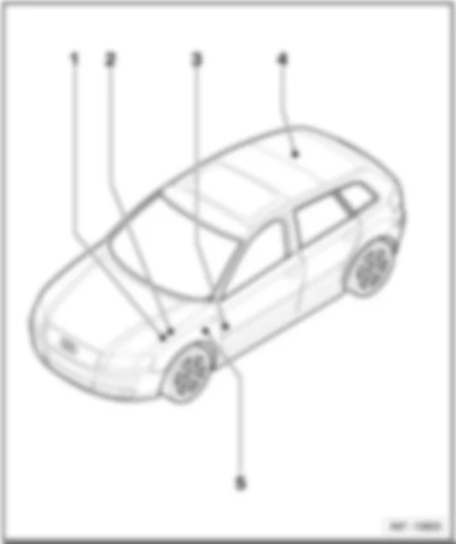
AUDI A3 2012 Overview of fuses
| q | Position of fuses on main fuse holder, electronics box low, from model year 2006 |
| q | Position of fuses on main fuse holder, electronics box low, from model year 2007 |
| q | Location on main fuse holder, electronics box low, from November 2008 |
| q | Position of fuses on main fuse holder, electronics box low, from November 2008 |
| q | Location main fuse holder, electronics box high |
| q | Position of fuses on main fuse holder, electronics box high, from model year 2004 |
| q | Position of fuses on main fuse holder, electronics box high, from model year 2005 |
| q | Position of fuses on main fuse holder, electronics box high, from model year 2006 |
| q | Position of fuses, electronics box low, from model year 2006 |
| q | Position of fuses, electronics box low, from model year 2007 |
| q | Fitting location of E-box high |
| q | Position of fuses, electronics box high, from model year 2004 |
| q | Position of fuses, electronics box high, from model year 2006 |
| q | Position of fuses, electronics box high, from model year 2007 |
| q | Position of fuses, from model year 2004 |
| q | Position of fuses, from model year 2006 |
| q | Position of fuses, from model year 2007 |
| q | Position of fuses on main fuse box, from model year 2004 |
| q | Position of fuses on main fuse box, from model year 2006 |
| 5 - |
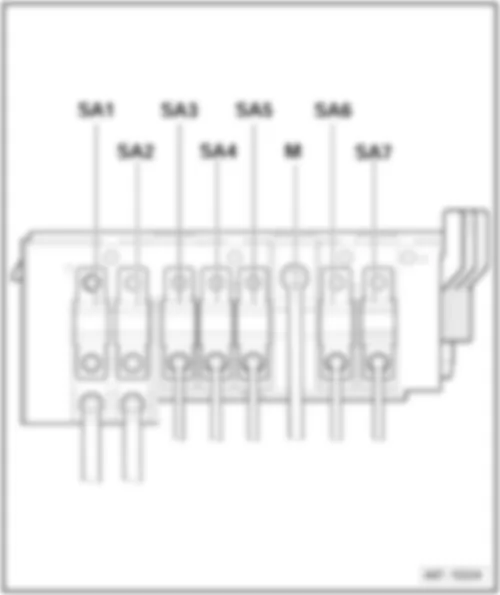
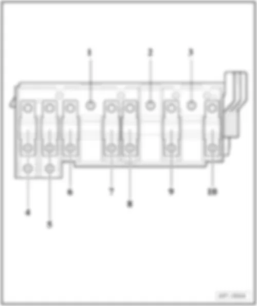
| Main fuse holder: Location fuse holder A -SA- on electronics box low, from model year 2006 |
| Main Supply Connection: |
| M - | Screw connection M (terminal 30) |
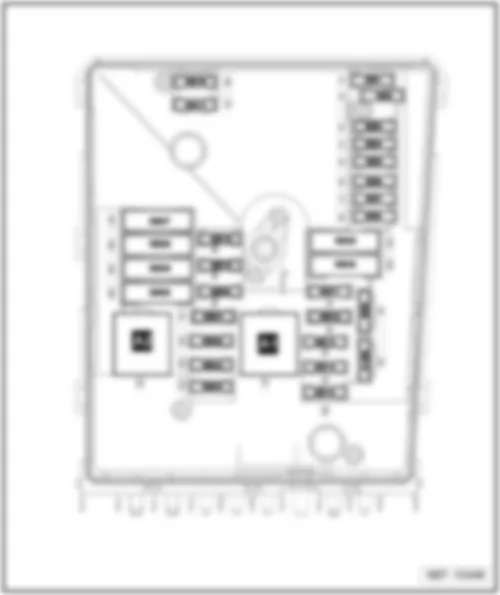
| Position of fuses electronics box low, from model year 2006 |
| Current Flow Diagram designation | Nominal value | Function/component | Terminal | |||
| Fuse 1 on fuse holder A -SA1- | 150 A | - | Alternator -C- (70 A) Alternator -C- (90 A) Alternator -C- (110 A) Alternator -C- (120 A) | 30 | ||
| 200 A | - | Alternator -C- (140 A) | 30 | |||
| Fuse 2 on fuse holder A -SA2- | 80 A | - | Power steering control unit -J500- | 30 | ||
| Fuse 3 on fuse holder A -SA3- | 50 A | - | Radiator fan control unit -J293- Radiator fan thermal switch -F18- Radiator fan -V7- | 30 | ||
| Fuse 4 on fuse holder A -SA4- | 80 A | - | Supply for the fuses: -SC12- up to -SC17-, -SC19-, -SC22- up to -SC27-, -SC28-, -SC38- is dropped from November 2005 | 30 | ||
| Fuse 5 on fuse holder A -SA5- | 80 A | - | Supply for the fuses: -SC12- up to -SC17-, -SC19-, -SC22- up to -SC27-, -SC28-, -SC38- applicable from November 2005 | 30 | ||
| Fuse 5 on fuse holder A -SA5- | 100 A | - | Auxiliary air heater control unit -J604- is dropped from November 2005 | 30 | ||
| Fuse 6 on fuse holder A -SA6- | 100 A | - | Auxiliary air heater control unit -J604- applicable from November 2005 | 30 | ||
| Fuse 7 on fuse holder A -SA7- | 50 A | - | Option doctor | 30 | ||
| 80 A | - | Option police | 30 | |||
| Position of fuses electronics box low, from model year 2007 |
| Current Flow Diagram designation | Nominal value | Function/component | Terminal | |||
| Fuse 1 on fuse holder A -SA1- | 150 A | - | Alternator -C- (70 A) Alternator -C- (90 A) Alternator -C- (110 A) Alternator -C- (120 A) | 30 | ||
| 200 A | - | Alternator -C- (140 A) | 30 | |||
| Fuse 2 on fuse holder A -SA2- | 80 A | - | Power steering control unit -J500- | 30 | ||
| Fuse 3 on fuse holder A -SA3- | 50 A | - | Radiator fan control unit -J293- Radiator fan thermal switch -F18- Radiator fan -V7- | 30 | ||
| Fuse 4 on fuse holder A -SA4- | 40 A | - | Low heat output relay -J359- applicable from November 2006 | 30 | ||
| Fuse 5 on fuse holder A -SA5- | 80 A | - | B272 Positive connection (30), in main wiring harness Supply for the fuses: -SC12- up to -SC17-, -SC22- up to -SC27-, -SC28-, -SC38-, -SC43- | 30 | ||
| Fuse 6 on fuse holder A -SA6- | 100 A | - | Auxiliary air heater control unit -J604- is dropped from November 2006 | 30 | ||
| Fuse 6 on fuse holder A -SA6- | 80 A | - | High heat output relay -J360- applicable from November 2006 | 30 | ||
| Fuse 7 on fuse holder A -SA7- | 50 A | - | Option doctor | 30 | ||
| 80 A | - | Option police | 30 | |||
| 30 A | - | Electronically controlled damping control unit -J 250- applicable from May 2008 | 30 | |||
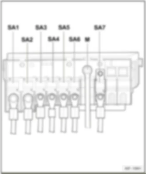
| Main fuse holder: Location fuse holder A -SA- on electronics box low, from November 2008 |
| Main Supply Connection: |
| M - | Screw connection M (terminal 30) |
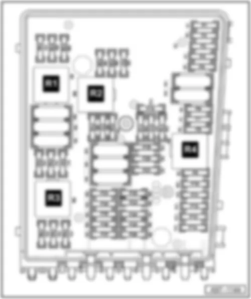
| Position of fuses in electronics box low, from November 2008 |
| Current Flow Diagram designation | Nominal value | Function/component | Terminal | |||
| Fuse 1 on fuse holder A -SA1- | 150 A | - | Alternator -C- (70 A) Alternator -C- (90 A) Alternator -C- (110 A) Alternator -C- (120 A) | 30 | ||
| 200 A | - | Alternator -C- (140 A) | 30 | |||
| Fuse 2 on fuse holder A -SA2- | 80 A | - | Power steering control unit -J500- | 30 | ||
| Fuse 3 on fuse holder A -SA3- | 50 A | - | Radiator fan control unit -J293- Radiator fan thermal switch -F18- Radiator fan -V7- | 30 | ||
| Fuse 4 on fuse holder A -SA4- | 80 A | - | High heat output relay -J360- | 30 | ||
| Fuse 5 on fuse holder A -SA5- | 80 A | - | B272 Positive connection (30), in main wiring harness Supply for the fuses: -SC12- up to -SC17-, -SC22- up to -SC27-, -SC28-, -SC38-, -SC43- | 30 | ||
| Fuse 6 on fuse holder A -SA6- | 40 A | - | Low heat output relay -J359- | 30 | ||
| Fuse 7 on fuse holder A -SA7- | 50 A | - | Option doctor is dropped from May 2009 | 30 | ||
| 50 A | - | Option doctor or police applicable from May 2009 | 30 | |||
| 80 A | - | Option police is dropped from May 2009 | 30 | |||
| 30 A | - | Electronically controlled damping control unit -J 250- | 30 | |||
| Main fuse holder: Location fuse holder A -SA- on electronics box high |
| Main Supply Connection: |
| 1 - | Screw connection A (terminal 30) |
| 2 - | Screw connection M (terminal 30) |
| 3 - | Screw connection L (terminal 30) |
| Position of fuses electronics box high, from model year 2004 |
| No. | Current Flow Diagram designation | Nominal value | Function/component | Terminal | ||
| 4 | - | Fuse 1 on fuse holder A -SA1- | 150 A | - | Alternator -C- (70 A) Alternator -C- (90 A) Alternator -C- (110 A) Alternator -C- (120 A) | 30 |
| 4 | - | Fuse 1 on fuse holder A -SA1- | 200 A | - | Alternator -C- (140 A) | 30 |
| 5 | - | Fuse 2 on fuse holder A -SA2- | 80 A | - | Power steering control unit -J500- | 30 |
| 6 | - | Fuse 3 on fuse holder A -SA3- | 80 A | - | Radiator fan control unit -J293- | 30 |
| 7 | - | Fuse 4 on fuse holder A -SA4- | 80 A | - | Window regulator single fuse -S37- Supply for the fuses: -SC22- up to -SC27- for models with battery in luggage compartment only | 30 |
| 8 | - | Fuse 5 on fuse holder A -SA5- | 100 A | - | Auxiliary air heater control unit -J604- | 30 |
| 9 | - | Fuse 6 on fuse holder A -SA6- | 50 A | - | Supply for the fuses: -SC12- up to -SC17-, -SC44-, -SC45- for models with battery in luggage compartment only | 30 |
| 80 A | - | Window regulator single fuse -S37- Supply for the fuses: -SC12- up to -SC17-, -SC22- up to -SC27- for models with battery in engine compartment only | 30 |
| Position of fuses electronics box high, from model year 2005 |
| No. | Current Flow Diagram designation | Nominal value | Function/component | Terminal | ||
| 4 | - | Fuse 1 on fuse holder A -SA1- | 150 A | - | Alternator -C- (70 A) Alternator -C- (90 A) Alternator -C- (110 A) Alternator -C- (120 A) | 30 |
| 4 | - | Fuse 1 on fuse holder A -SA1- | 200 A | - | Alternator -C- (140 A) | 30 |
| 5 | - | Fuse 2 on fuse holder A -SA2- | 80 A | - | Power steering control unit -J500- | 30 |
| 6 | - | Fuse 3 on fuse holder A -SA3- | 80 A | - | Radiator fan control unit -J293- | 30 |
| 7 | - | Fuse 4 on fuse holder A -SA4- | 80 A | - | Window regulator single fuse -S37- Window regulator single fuse 2 -S280- Supply for the fuses: -SC22- up to -SC27- for models with battery in luggage compartment only | 30 |
| 8 | - | Fuse 5 on fuse holder A -SA5- | 100 A | - | Auxiliary air heater control unit -J604- | 30 |
| 9 | - | Fuse 6 on fuse holder A -SA6- | 50 A | - | Supply for the fuses: -SC12- up to -SC17-, -SC19-, -SC44-, -SC45- for models with battery in luggage compartment only | 30 |
| 80 A | - | Window regulator single fuse -S37- Window regulator single fuse 2 -S280- Supply for the fuses: -SC12- up to -SC17-, -SC19-, -SC22- up to -SC27- for models with battery in engine compartment only | 30 |
| No. | Current Flow Diagram designation | Nominal value | Function/component | Terminal | ||
| 4 | - | Fuse 1 on fuse holder A -SA1- | 150 A | - | Alternator -C- (70 A) Alternator -C- (90 A) Alternator -C- (110 A) Alternator -C- (120 A) | 30 |
| 200 A | - | Alternator -C- (140 A) | ||||
| 5 | - | Fuse 2 on fuse holder A -SA2- | 80 A | - | Power steering control unit -J500- | 30 |
| 6 | - | Fuse 3 on fuse holder A -SA3- | 50 A | - | Radiator fan control unit -J293- | 30 |
| 7 | - | Fuse 4 on fuse holder A -SA4- | 80 A | - | Supply for the fuses: -SC12- up to -SC17-, -SC19-, -SC22- up to -SC27-, -SC28-, -SC38- is dropped from November 2005 | 30 |
| 7 | - | Fuse 4 on fuse holder A -SA4- | 80 A | - | Supply for the fuses: -SC12- up to -SC17-, -SC22- up to -SC27-, -SC28-, -SC38-, -SC43- applicable from May 2009 | 30 |
| 8 | - | Fuse 5 on fuse holder A -SA5- | 80 A | - | Supply for the fuses: -SC12- up to -SC17-, -SC19-, -SC22- up to -SC27-, -SC28-, -SC38- applicable from November 2005 is dropped from May 2006 | 30 |
| 8 | - | Fuse 5 on fuse holder A -SA5- | 80 A | - | Supply for the fuses: -SC12- up to -SC17-, -SC22- up to -SC27-, -SC28-, -SC38-, -SC43- applicable from May 2006 is dropped from May 2009 | 30 |
| 9 | - | Fuse 6 on fuse holder A -SA6- | - | - | Not assigned | - |
| 10 | - | Fuse 7 on fuse holder A -SA7- | 50 A | - | Option doctor is dropped from May 2009 | 30 |
| 50 A | Option doctor or police applicable from May 2009 | |||||
| 80 A | Option police is dropped from May 2009 | |||||
| 30 A | Electronically controlled damping control unit -J 250- applicable from May 2008 |
| Fuse colours |
| 50A - red |
| 40A - orange |
| 30A - light-green |
| 25A - natural (white) |
| 20 A - yellow |
| 15A - light blue |
| 10A - red |
| 7.5A - brown |
| 5A - light-brown |
| 3 A - purple |
| Position of fuses electronics box low, from model year 2006 |
| No. | Current Flow Diagram designation | Nominal value | Function/component | Terminal | ||
| F1 | - | Fuse 1 on fuse holder B -SB1- | 20 A | - | Convenience system central control unit -J393- | 30 |
| F2 | - | Fuse 2 on fuse holder B -SB2- | 5 A | - | Steering column electronics control unit -J527- | 30 |
| F3 | - | Fuse 3 on fuse holder B -SB3- | 5 A | - | Onboard supply control unit -J519- | 30 |
| F4 | - | Fuse 4 on fuse holder B -SB4- | 30 A | - | ABS control unit -J104- ABS hydraulic unit -N55- | 30 |
| F5 | - | Fuse 5 on fuse holder B -SB5- | 15 A | - | Mechatronic unit for dual clutch gearbox -J743- | 30 |
| F6 | - | Fuse 6 on fuse holder B -SB6- | 5 A | - | Control unit in dash panel insert -J285- | 30 |
| F7 | - | Not assigned | - | - | ||
| F8 | - | Fuse 8 on fuse holder B -SB8- | 15 A | - | Radio -R- Navigation operating electronics control unit -J402- | 30 |
| F9 | - | Fuse 9 on fuse holder B -SB9- | 5 A | - | Navigation system with CD drive control unit -J401- Navigation system tuner for TV -J415- Satellite radio -R146- Telephone transmitter and receiver unit -R36- Aerial amplifier for mobile telephone -R86- | 30 |
| F10 | - | Fuse 10 on fuse holder B -SB10- | 5 A | - | Motronic control unit -J220- Motronic current supply relay -J271- Terminal 30 voltage supply relay -J317- | 30 |
| F11 | - | Fuse 11 on fuse holder B -SB11- | 20 A | - | Auxiliary heater control unit -J364- | 30 |
| F12 | - | Fuse 12 on fuse holder B -SB12- | 5 A | - | Data bus diagnostic interface -J533- | 30 |
| F13 | - | Fuse 13 on fuse holder B -SB13- | 30 A | - | Engine control unit -J623- Diesel direct injection system control unit -J248- | 87 |
| 25 A | - | Motronic control unit -J220- Engine control unit -J623- | ||||
| F14 | - | Fuse 14 on fuse holder B -SB14- | 20 A | - | Ignition coil 1 with output stage -N- Ignition coil 2 -N128- Ignition coil 1 with output stage -N70- Ignition coil 2 with output stage -N127- Ignition coil 3 with output stage -N291- Ignition coil 4 with output stage -N292- | 87 |
| F15 | - | Fuse 15 on fuse holder B -SB15- | 15 A | - | Lambda probe 1 heater after catalytic converter -Z29- Lambda probe 2 heater after catalytic converter -Z30- Lambda probe 3 heater after catalytic converter -Z64- | 87 |
| F15 | - | Fuse 15 on fuse holder B -SB15- | 10 A | - | Lambda probe 1 heater after catalytic converter -Z29- | 87 |
| F15 | - | Fuse 15 on fuse holder B -SB15- | 5 A | - | Automatic glow period control unit -J179- Fuel pump relay -J17- | 87 |
| F16 | - | Fuse 16 on fuse holder B -SB16- | 30 A | - | ABS control unit -J104- ABS hydraulic pump -V64- | 30 |
| F17 | - | Fuse 17 on fuse holder B -SB17- | 15 A | - | High tone horn -H2- Low tone horn -H7- | 30 |
| F18 | - | Fuse 18 on fuse holder B -SB18- | 30 A | - | Amplifier -R12- Amplifier with bass loudspeaker, on left in luggage compartment -R44- | 30 |
| F19 | - | Fuse 19 on fuse holder B -SB19- | 30 A | - | Wiper motor control unit -J400- | 30 |
| F21 | - | Fuse 21 on fuse holder B -SB21- | 15 A | - | Lambda probe heater -Z19- Lambda probe 2 heater -Z28- Lambda probe 1 heater after catalytic converter -Z29- | 87 |
| 10 A | - | Lambda probe heater -Z19- | ||||
| F22 | - | Fuse 22 on fuse holder B -SB22- | 5 A | - | Brake pedal switch -F63- Clutch position sender -G476- | 87 |
| F23 | - | Fuse 23 on fuse holder B -SB23- | 15 A | - | Fuel pressure regulating valve -N276- | 87 |
| 10 A | - | Exhaust gas recirculation valve -N18- Charge pressure control solenoid valve -N75- Exhaust gas recirculation valve 2 -N213- Exhaust gas recirculation cooler change-over valve -N345- | ||||
| 5 A | - | Secondary air pump relay -J299- | ||||
| F24 | - | Fuse 24 on fuse holder B -SB24- | 10 A | - | Map-controlled engine cooling system thermostat -F265- Activated charcoal filter system solenoid valve 1 -N80- Variable intake manifold change-over valve -N156- Camshaft control valve 1 -N205- Intake manifold flap motor -V157- | 87 |
| F25 | - | Fuse 25 on fuse holder B -SB25- | 40 A | - | Onboard supply control unit -J519- (right side light, right main beam, right dipped beam, right turn signal, right fog light) | 30 |
| F26 | - | Fuse 26 on fuse holder B -SB26- | 40 A | - | Onboard supply control unit -J519- (left side light, left main beam, left dipped beam, left turn signal, left fog light) | 30 |
| F27 | - | Fuse 27 on fuse holder B -SB27- | 50 A | - | Automatic glow period control unit -J179- Glow plug 1 -Q10- Glow plug 2 -Q11- Glow plug 3 -Q12- Glow plug 4 -Q13- | 87 |
| 40 A | Secondary air pump motor -V101- | |||||
| F28 | - | Fuse 28 on fuse holder B -SB28- | 40 A | - | Terminal 15 voltage supply relay 2 -J681- Supply for the fuses: -SC1- up to -SC6-, -SC7- up to -SC11-, -SC29- up to -SC31-, -SC39-, -SC47-, -SC49- | 30 |
| F29 | - | Fuse 29 on fuse holder B -SB29- | 50 A | - | Supply for the fuses: -SC18-, -SC20-, -SC32- up to -SC37-, -SC44-, -SC45-, -SC48-, -S131- | 30 |
| F30 | - | Fuse 30 on fuse holder B -SB30- | 50 A 1 | - | X-contact relief relay -J59- Supply for the fuses: -SC40-, -SC41-, -SC42-, -SC46- | 30 |
| Note:
|
| Position of fuses electronics box low, from model year 2007 |
| No. | Current Flow Diagram designation | Nominal value | Function/component | Terminal | ||
| F1 | - | Fuse 1 on fuse holder B -SB1- | 40 A | - | Voltage stabiliser -J532- Supply for the fuses: -SC7- up to -SC11- only models with stop/start system applicable from model year 2010 | 30 |
| F1 | - | Fuse 1 on fuse holder B -SB1- | 40 A | - | Supply for the fuses: -SC7- up to -SC10- only models without stop/start system applicable from model year 2010 | 30 |
| F2 | - | Fuse 2 on fuse holder B -SB2- | 5 A | - | Steering column electronics control unit -J527- is dropped from model year 2009 | 30 |
| F2 | - | Fuse 2 on fuse holder B -SB2- | 30 A | - | Mechatronic unit for dual clutch gearbox -J743- (7-speed dual clutch gearbox 0AM) applicable from model year 2009 | 30 |
| F2 | - | Fuse 2 on fuse holder B -SB2- | 20 A | - | Fuel pressure regulating valve -N276- (CBFA) applicable from model year 2009 is dropped from May 2011 | 30 |
| F2 | - | Fuse 2 on fuse holder B -SB2- | 15 A | - | Fuel pressure regulating valve -N276- (CBFA) applicable from May 2011 | 30 |
| F3 | - | Fuse 3 on fuse holder B -SB3- | 5 A | - | Onboard supply control unit -J519- | 30 |
| F3 | - | Fuse 3 on fuse holder B -SB3- | 5 A | - | Battery monitor control unit -J367- applicable from model year 2010 | 30 |
| F4 | - | Fuse 4 on fuse holder B -SB4- | 30 A | - | ABS control unit -J104- (MK60 ESP valves) ABS control unit -J104- (MK70 ABS valves) is dropped from model year 2009 | 30 |
| F4 | - | Fuse 4 on fuse holder B -SB4- | 20 A | - | ABS control unit -J104- (MK60 ESP valves) applicable from model year 2009 | 30 |
| F5 | - | Fuse 5 on fuse holder B -SB5- | 15 A | - | Mechatronic unit for dual clutch gearbox -J743- | 30 |
| F6 | - | Fuse 6 on fuse holder B -SB6- | 5 A | - | Control unit in dash panel insert -J285- is dropped from model year 2010 | 30 |
| F6 | - | Fuse 6 on fuse holder B -SB6- | 5 A | - | Steering column electronics control unit -J527- applicable from model year 2009 | 30 |
| F7 | - | Fuse 7 on fuse holder B -SB7- | 20 A | - | Fuel pressure regulating valve -N276- (CBFA) is dropped from model year 2009 | 30 |
| F8 | - | Fuse 8 on fuse holder B -SB8- | 15 A | - | Navigation operating electronics control unit -J402- Control unit with display for radio and navigation system -J503- Radio -R- is dropped from model year 2010 | 30 |
| F8 | - | Fuse 8 on fuse holder B -SB8- | 25 A | - | Control unit with display for radio and navigation -J503-1 with radio navigation system (models for Japan) only is dropped from model year 2010 | 30 |
| F9 | - | Fuse 9 on fuse holder B -SB9- | 5 A | - | Navigation system with CD drive control unit -J401-1 Navigation system tuner for TV -J415-1 Satellite radio -R146- Telephone transmitter and receiver unit -R36- Aerial amplifier for mobile telephone -R86-1 18-pin connector -T18a- (VDA interface) 1 is dropped from model year 2010 | 30 |
| F10 | - | Fuse 10 on fuse holder B -SB10- | 5 A | - | Terminal 30 voltage supply relay -J317- (BKC, BXE, AZV, BKD, BLS, BMM, BUY, BMN, CBBB, CBAB, CBAA, CAYB, CAYC, CBEA, CFFA, CFFB, CFGB, CLJA) | 30 |
| F10 | Fuse 10 on fuse holder B -SB10- | 5 A | - | Engine control units -J...- (CMSA, CAXC, CBBB, CBAB, CBAA, CAYB, CAYC, CBEA, CBZB, CFFA, CFFB, CFGB, CLJA) Motronic current supply relay -J271- (CAXC, CBZB) | 30 | |
| F10 | - | Fuse 10 on fuse holder B -SB10- | 10 A | - | Engine control units -J...- (BLF, BPT, BPU, BVZ, BVY, BZB, CAWB, CBFA, CCTA, CDAA, CCZA) Motronic current supply relay -J271- (BLF, BPT, BPU, BVZ, BVY, BZB, CAWB, CBFA, CCTA, CDAA, CCZA) | 30 |
| F11 | - | Fuse 11 on fuse holder B -SB11- | 20 A | - | Auxiliary heater control unit -J364-1 is dropped from November 2010 | 30 |
| F11 | - | Fuse 11 on fuse holder B -SB11- | 30 A | - | Auxiliary heater control unit -J364-1 applicable from November 2010 | 30 |
| F12 | - | Fuse 12 on fuse holder B -SB12- | 5 A | - | Data bus diagnostic interface -J533- | 30 |
| F13 | - | Fuse 13 on fuse holder B -SB13- | 30 A | - | Engine control units -J...- (BKC, BXE, AZV, BKD, BLS, BMM, BUY, BMN, CBBB, CBAB, CBAA, CAYB, CAYC, CBEA, CFFA, CFFB, CFGB, CLJA) | 87 |
| 25 A | Engine control units -J...- (BLF, BPT, BPU, BYT, BVZ, BVY, BSE, BSF) is dropped from May 2007, for models with engine codes BSE, BSF only | |||||
| 15 A | Engine control units -J...- (CMSA, CAXC, BZB, CAWB, CBFA, CCTA, CDAA, CCZA, CBZB) applicable from May 2007, for models with engine codes BSE, BSF, CCSA, CMXA only | |||||
| F14 | Fuse 14 on fuse holder B -SB14- | 20 A | - | Ignition coil 1 with output stage -N- (BSE, BSF, CCSA, CBZB, CMXA) Ignition coil 2 -N128- (BSE, BSF, CCSA, CBZB, CMXA) | 87 | |
| F14 | - | Fuse 14 on fuse holder B -SB14- | 20 A | - | Ignition coil 1 with output stage -N70- Ignition coil 2 with output stage -N127- Ignition coil 3 with output stage -N291- Ignition coil 4 with output stage -N292- for models with engine codes BLF, BPT, BPU, BYT, BVZ, BVY, CAXC, CMSA, BZB, CAWB, CBFA, CCTA, CDAA, CCZA only | 87 |
| F14 | - | Fuse 14 on fuse holder B -SB14- | 20 A | - | Fuel pressure regulating valve -N276- (CBBB, CBAB, CBAA, CAYB, CAYC, CBEA, CFFA, CFFB, CFGB, CLJA) Fuel metering valve -N290- (CBBB, CBAB, CBAA, CAYB, CAYC, CBEA, CFFA, CFFB, CFGB, CLJA) is dropped from May 2011 | 87 |
| F14 | - | Fuse 14 on fuse holder B -SB14- | 15 A | - | Fuel pressure regulating valve -N276- (CBBB, CBAB, CBAA, CAYB, CAYC, CBEA, CFFA, CFFB, CFGB, CLJA) Fuel metering valve -N290- (CBBB, CBAB, CBAA, CAYB, CAYC, CBEA, CFFA, CFFB, CFGB, CLJA) Throttle valve module -J338- (CBEA) Radiator fan control unit -J293- (CBEA) applicable from May 2011 | 87 |
| F15 | - | Fuse 15 on fuse holder B -SB15- | 15 A | - | Lambda probe 1 heater after catalytic converter -Z29-(BVY) Lambda probe 2 heater after catalytic converter -Z30- (BVY) Lambda probe 3 heater after catalytic converter -Z64- (BVY) | 87 |
| F15 | - | Fuse 15 on fuse holder B -SB15- | 10 A | - | Lambda probe 1 heater after catalytic converter -Z29- (BVZ) | 87 |
| F15 | - | Fuse 15 on fuse holder B -SB15- | 10 A | - | Lambda probe 1 heater after catalytic converter -Z29- (CAXC, CBZB, CMSA) Lambda probe heater -Z19- (CAXC, CBZB, CMSA) | 87 |
| F15 | - | Fuse 15 on fuse holder B -SB15- | 10 A | - | Camshaft control valve 1 -N205- (BPT, BPU, BYT) | 87 |
| F15 | Fuse 15 on fuse holder B -SB15- | 10 A | - | Radiator identification sensor -G611- (CBFA) Fuel system diagnostic pump -V144- (CBFA, CCTA) Lambda probe heater -Z19- (CBFA) | 87 | |
| F15 | - | Fuse 15 on fuse holder B -SB15- | 5 A | - | Fuel pump relay -J17- Automatic glow period control unit -J179- for models with engine codes BKC, BXE, AZV, BKD, BLS, BMM, BUY, BMN, CBBB, CBAB, CBAA, CAYB, CAYC, CBEA, CFFA, CFFB, CFGB, CLJA | 87 |
| F15 | - | Fuse 15 on fuse holder B -SB15- | 5 A | - | Low heat output relay -J359- High heat output relay -J360- for models with engine codes BKC, BXE, AZV, BKD, BLS, BMM, BUY, BMN, CBBB, CBAB, CBAA, CAYB, CAYC, CBEA, CFFA, CFFB, CFGB, CLJA applicable from November 2006, only for models with auxiliary air heater | 87 |
| F15 | - | Fuse 15 on fuse holder B -SB15- | 5 A | - | Supplementary fuel pump relay -J832- (CBBB, CBAB, CBAA, CBEA, CFFA, CFFB, CFGB, CLJA) | 87 |
| F16 | - | Fuse 16 on fuse holder B -SB16- | 30 A | - | ABS control unit -J104- (ABS pump) is dropped from model year 2009 | 30 |
| F16 | - | Fuse 16 on fuse holder B -SB16- | 30 A | - | Onboard supply control unit -J519- Right side light supply, right main beam, right dipped beam, right turn signal, right fog light applicable from model year 2009 | 30 |
| F17 | - | Fuse 17 on fuse holder B -SB17- | 15 A | - | High tone horn -H2- Low tone horn -H7- | 30 |
| F18 | - | Fuse 18 on fuse holder B -SB18- | 30 A | - | Amplifier -R12- Amplifier with bass loudspeaker, on left in luggage compartment -R44- | 30 |
| F18 | - | Fuse 18 on fuse holder B -SB18- | 30 A | - | Voltage stabiliser -J532- Amplifier -R12- Amplifier with bass loudspeaker, on left in luggage compartment -R44- only models with stop/start system applicable from model year 2010 | 30 |
| F19 | - | Fuse 19 on fuse holder B -SB19- | 30 A | - | Wiper motor control unit -J400- | 30 |
| F20 | - | Fuse 20 on fuse holder B -SB20- | 20 A | - | Fuel pressure regulating valve -N276- (BYT, BPT, BPU, BZB, CAWB, CCTA, CDAA, CCZA) is dropped from May 2011 | 87 |
| F20 | - | Fuse 20 on fuse holder B -SB20- | 15 A | - | Fuel pressure regulating valve -N276- (BYT, BPT, BPU, BZB, CAWB, CCTA, CDAA, CCZA) applicable from May 2011 | 87 |
| F20 | - | Fuse 20 on fuse holder B -SB20- | 10 A | - | Coolant circulation pump -V50- (CAXC, CMSA) | 87 |
| F21 | - | Fuse 21 on fuse holder B -SB21- | 10 A | - | Lambda probe 3 heater after catalytic converter -Z64- (CBFA) | 87 |
| F21 | - | Fuse 21 on fuse holder B -SB21- | 10 A | - | Lambda probe heater -Z19- (BSE, BSF, BLF, BPT, BPU, BYT, BVZ, BVY, BLS, BMM, BUY, BMN, BZB, CAWB, CCTA, CCSA, CDAA, CCZA, CBBB, CBAB, CBAA, CAYB, CAYC, CBEA, CFFA, CFFB, CFGB) Lambda probe 1 heater after catalytic converter -Z29- (BSE, BSF, BLF, CCTA, CBFA, CCSA, CDAA, CCZA, CBEA) is dropped from May 2009, for models with engine codes BSF, BSE, CCSA, CCTA, CCZA, CDAA only | 87 |
| F21 | - | Fuse 21 on fuse holder B -SB21- | 15 A | - | Lambda probe heater -Z19- (BSE, CCSA, CCTA, CCZA, CDAA, CMXA, BSF) Lambda probe 1 heater after catalytic converter -Z29- (BSE, CCSA, CCTA, CCZA, CDAA, CMXA, BSF) applicable from model year 2010 | 87 |
| F21 | - | Fuse 21 on fuse holder B -SB21- | 20 A | - | Vacuum pump relay -J57- (CAXC, CMSA) Vacuum pump for brakes -V192- (CAXC, CMSA) | 87 |
| F22 | Fuse 22 on fuse holder B -SB22- | 5 A | Clutch position sender -G476- | 87 | ||
| F22 | Fuse 22 on fuse holder B -SB22- | 5 A | Brake light switch -F- Brake pedal switch -F63- applicable from model year 2010 | 87 | ||
| F23 | - | Fuse 23 on fuse holder B -SB23- | 5 A | - | Continued coolant circulation relay -J151- (BPT, BPU, BYT, BZB, CAWB, CCTA, CBFA, CCZA, CDAA) Secondary air pump relay -J299- (BSE, BSF, CBFA, CCSA, CMXA) Engine components current supply relay -J757- (CBFA) Continued coolant circulation pump -V51- (BPT, BPU, BYT, BZB, CAWB, CCTA, CBFA, CCZA, CDAA) | 87 |
| 10 A | Exhaust gas recirculation valve -N18- (BKC, BXE, AZV, BKD) Charge pressure control solenoid valve -N75- (BLS, BMM, BKC, BXE, AZV, BKD, BMN, BUY, CBBB, CBAB, CBAA, CAYB, CAYC, CBEA, CFFA, CFFB, CFGB, CLJA) Exhaust gas recirculation valve 2 -N213- (BKC, BXE, AZV, BKD) Intake manifold flap valve -N316- (BMN, BUY) Exhaust gas recirculation cooler change-over valve -N345- (BLS, BMM) Exhaust gas recirculation cooler change-over valve -N345- (BMN, BUY, CBBB, CBAB, CBAA, CAYB, CAYC, CFFA, CFFB, CFGB, CLJA) | |||||
| 10 A | Air mass meter -G70- (CFFA, CFFB, CFGB, CLJA) | |||||
| 15 A | Fuel pressure regulating valve -N276- (BLF, CAXC, BVY, BVZ, CBZB, CMSA) | |||||
| F24 | - | Fuse 24 on fuse holder B -SB24- | 10 A | - | Radiator fan control unit -J293- Additional coolant pump relay -J496- (CAXC, CMSA) Engine component current supply relay -J757- (BPT, BPU, BYT, CAXC, CDAA, CAWB, CCZA, CCTA) Throttle valve module -J338- (CBEA) Charge pressure control solenoid valve -N75- (BPT, BPU, BYT, CAXC, CMSA, CAWB, BZB, CCTA, CBFA, CDAA, CCZA) Activated charcoal filter solenoid valve 1 -N80- (BPT, BPU, BYT, BSE, BSF, BLF, BVY, BVZ, CMSA, CAXC, CAWB, BZB, CCTA, CBFA, CCSA, CDAA, CCZA, CBZB, CMXA) Secondary air inlet valve -N112- (CBFA) Variable intake manifold change-over valve -N156- (BSE, BSF, BLF, BVY, BVZ, CCSA, CMXA) Inlet camshaft control valve 1 -N205- (BLF, BVY, BVZ, CAXC, CAWB, BZB, CMSA, CCTA, CBFA, CDAA, CCZA) Turbocharger air recirculation valve -N249- (BPT, BPU, BYT, CMSA, CAXC, CAWB, BZB, CCTA, CBFA, CDAA, CCZA) Intake manifold flap valve -N316- (BPT, BPU, BYT, CAWB, BZB, CCTA, CBFA, CDAA, CCZA, CBZB) Oil pressure control valve -N428- Intake manifold flap motor -V157- (BKC, BXE, AZV, BKD) Pump for exhaust gas recirculation cooler -V400- (CBBB, CBAB, CBAA, CAYB, CAYC, CFFA, CFFB, CFGB, CLJA) Electrohydraulic engine mounting solenoid valve -N398- (CAYB, CAYC) | 87 |
| F25 | - | Fuse 25 on fuse holder B -SB25- | 30 A | - | Onboard supply control unit -J519- Right side light supply, right main beam, right dipped beam, right turn signal, right fog light is dropped from model year 2009 | 30 |
| F25 | - | Fuse 25 on fuse holder B -SB25- | 40 A | - | ABS control unit -J104- (MK60 ESP pump) ABS control unit -J104- (MK70 ABS pump and ABS valves) applicable from model year 2009 | 30 |
| F26 | - | Fuse 26 on fuse holder B -SB26- | 30 A | - | Onboard supply control unit -J519- Left side light supply, left main beam, left dipped beam, left turn signal, left fog light | 30 |
| F27 | - | Fuse 27 on fuse holder B -SB27- | 50 A | - | Automatic glow period control unit -J179- Glow plug 1 -Q10- Glow plug 2 -Q11- Glow plug 3 -Q12- Glow plug 4 -Q13- for models with engine codes BKC, BXE, AZV, BKD, BLS, BMM, BUY, BMN, CBBB, CBAB, CBAA, CAYB, CAYC, CBEA, CFFA, CFFB, CFGB, CLJA only | 87 |
| F27 | - | Fuse 27 on fuse holder B -SB27- | 40 A | - | Secondary air pump motor -V101- (BSF, BSE, CBFA, CCSA, CMXA) | 87 |
| F28 | - | Fuse 28 on fuse holder B -SB28- | 40 A | - | Terminal 15 voltage supply relay 2 -J681- Supply for the fuses: -SC1- up to -SC6-, -SC29- up to -SC31-, -SC46-, -SC47-, -SC49- is dropped from model year 2009 | 30 |
| F29 | - | Fuse 29 on fuse holder B -SB29- | 50 A | - | B300 Positive connection 4 (30), in main wiring harness Supply for the fuses: -SC32- up to -SC37-, -SC44-, -SC45-, -SC48-, -S131- is dropped from model year 2009 | 30 |
| F29 | - | Fuse 29 on fuse holder B -SB29- | 50 A | - | B300 Positive connection 4 (30), in main wiring harness Supply for the fuses: -SC32- up to -SC37-, -SC39-, -SC44-, -SC45-, -SC48-, -S131- applicable from model year 2009 | 30 |
| F30 | - | Fuse 30 on fuse holder B -SB30- | 50 A | - | X-contact relief relay -J59- Supply for the fuses: -SC40-, -SC41-, -SC42- is dropped from model year 2009 | 30 |
| F30 | - | Fuse 30 on fuse holder B -SB30- | 50 A | - | Terminal 15 voltage supply relay 2 -J681- Supply for the fuses: -SC1- up to -SC6-, -SC19-, -SC20-, -SC29- up to -SC31-, -SC40-, -SC41-, -SC42-, -SC46-, -SC47-, -SC49- applicable from model year 2009 | 30 |
|
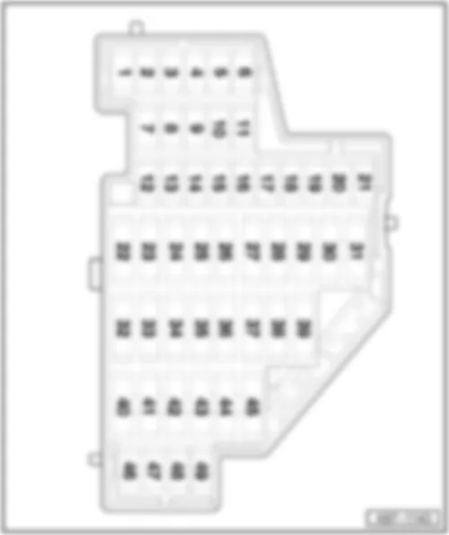
| Location fuse holder B -SB- on electronics box high, in left of engine compartment |
| Fuse colours |
| 50A - red |
| 40A - orange |
| 30A - light-green |
| 25A - natural (white) |
| 20 A - yellow |
| 15A - light blue |
| 10A - red |
| 7.5A - brown |
| 5A - light-brown |
| 3 A - purple |
| Position of fuses electronics box high, from model year 2004 |
| No. | Current Flow Diagram designation | Nominal value | Function/component | Terminal | ||
| F1 | - | Fuse 1 on fuse holder B -SB1- | 30 A | - | ABS hydraulic pump -V64- | 30 |
| F2 | - | Fuse 2 on fuse holder B -SB2- | 30 A | - | ABS hydraulic unit -N55- | 30 |
| F3 | - | Fuse 3 on fuse holder B -SB3- | 20 A | - | Convenience system central control unit -J393- | 30 |
| F4 | - | Fuse 4 on fuse holder B -SB4- | 5 A | - | Onboard supply control unit -J519- for models with battery in engine compartment only | 30 |
| F5 | - | Fuse 5 on fuse holder B -SB5- | 20 A | - | High tone horn -H2- Low tone horn -H7- | 30 |
| F6 | - | Fuse 6 on fuse holder B -SB6- | 7.5 A | - | Fuel pressure regulating valve -N276-1 is dropped, from model year 2005 | 87 (30a) |
| 15 A | - | Fuel pressure regulating valve -N276-1 applicable from model year 2005 | ||||
| 20 A | - | Output stage -N122-1 | ||||
| 30 A | - | Ignition coil 1 with output stage -N70- Ignition coil 2 with output stage -N127- Ignition coil 3 with output stage -N291- Ignition coil 4 with output stage -N292- Ignition coil 5 with output stage -N323-1 Ignition coil 6 with output stage -N324-1 | ||||
| F7 | - | Fuse 7 on fuse holder B -SB7- | 5 A | - | Brake light switch -F- Brake pedal switch -F63- Clutch travel sender -G162- | 87 (30a) |
| F8 | - | Fuse 8 on fuse holder B -SB8- | 10 A | - | Map-controlled engine cooling system thermostat -F265-1 Radiator fan control unit -J293- Exhaust gas recirculation valve -N18-1 Activated charcoal filter system solenoid valve 1 -N80-1 Variable intake manifold change-over valve -N156-1 Camshaft control valve 1 -N205- Exhaust camshaft control valve 1 -N318-1 Intake manifold flap motor -V157-1 | 87 (30a) |
| F9 | - | Fuse 9 on fuse holder B -SB9- | 10 A | - | Fuel pump relay -J17-1 Continued coolant circulation relay -J151- Automatic glow period control unit -J179-1 NOx sensor control unit -J583-1 Continued coolant circulation pump -V51- NOx sender heater -Z44-1 | 87 (30a) |
| F10 | - | Fuse 10 on fuse holder B -SB10- | 10 A | - | Secondary air pump relay -J299-1 Exhaust gas recirculation valve -N18-1 Charge pressure control solenoid valve -N75-1 Secondary air inlet valve -N112-1 Exhaust gas recirculation valve 2 -N213-1 Exhaust flap valve -N220-1 Lambda probe 1 heater after catalytic converter -Z29-1 Lambda probe 2 heater after catalytic converter -Z30-1 Fuel system diagnostic pump -V144- | 87 (30a) |
| F11 | - | Fuse 11 on fuse holder B -SB11- | 25 A | - | Motronic control unit -J220- Simos control unit -J361-1 | 87 (30a) |
| 30 A | - | Diesel direct injection system control unit -J248-1 | ||||
| F12 | - | Fuse 12 on fuse holder B -SB12- | 15 A | - | NOx sensor control unit -J583-1 Lambda probe heater -Z19-1 Lambda probe 2 heater -Z28-1 NOx sender heater -Z44-1 | 87 (30a) |
| F13 | - | Fuse 13 on fuse holder B -SB13- | 20 A | - | Mechatronic unit for dual clutch gearbox -J743- | 30 |
| F14 | - | Not assigned | - | - | - | |
| F15 | - | Fuse 15 on fuse holder B -SB15- | 40 A | - | Starter -B- | 87 (50) |
| F16 | - | Fuse 16 on fuse holder B -SB16- | 15 A | - | Steering column electronics control unit -J527- | 30 |
| F17 | - | Fuse 17 on fuse holder B -SB17- | 10 A | - | Control unit in dash panel insert -J285- | 30 |
| F18 | Fuse 18 on fuse holder B -SB18- | 30 A | - | Amplifier -R12- Amplifier with bass loudspeaker, on left in luggage compartment -R44- | 30 | |
| F19 | - | Fuse 19 on fuse holder B -SB19- | 15 A | - | Radio -R- Navigation operating electronics control unit -J402- | 30 |
| F20 | - | Fuse 20 on fuse holder B -SB20- | 5 A | - | Telephone transmitter and receiver unit -R36- Aerial amplifier for mobile telephone -R86-1 | 30 |
| F21 | - | Fuse 21 on fuse holder B -SB21- | 10 A | - | Navigation system with CD drive control unit -J401- Navigation system tuner for TV -J415-1 | 30 |
| F22 | - | Not assigned | - | - | - | |
| F23 | - | Not assigned | - | - | - | |
| F24 | - | Fuse 24 on fuse holder B -SB24- | 10 A | - | Data bus diagnostic interface -J533- | 30 |
| F25 | - | Not assigned | - | - | ||
| F26 | - | Fuse 26 on fuse holder B -SB26- | 10 A | - | Motronic control unit -J220- Motronic current supply relay -J271- | 30 |
| 5 A | - | Terminal 30 voltage supply relay -J317-1 | ||||
| F27 | - | Fuse 21 on fuse holder B -SB21- | 10 A | - | Crankcase breather heater element -N79-1 for models with heater element only | 87 (15) |
| 5 A | - | Crankcase breather heater element -N79-1 for models with heater element only | 87 (15) | |||
| F28 | Fuse 28 on fuse holder B -SB28- | 20 A | - | Automatic gearbox control unit -J217-1 | 87 (15) | |
| F29 | - | Fuse 29 on fuse holder B -SB29- | 10 A | - | Injector, cylinder 1 -N30-1 Injector, cylinder 2 -N31-1 Injector, cylinder 3 -N32-1 Injector, cylinder 4 -N33-1 Injector, cylinder 5 -N83-1 Injector, cylinder 6 -N84-1 | 87 (15) |
| 20 A | Ignition coil 1 with output stage -N70-1 Ignition coil 2 with output stage -N127-1 Ignition coil 3 with output stage -N291-1 Ignition coil 4 with output stage -N292-1 | |||||
| F30 | - | Fuse 30 on fuse holder B -SB30- | 20 A | - | Auxiliary heater control unit -J364-1 | 30 |
| F31 | - | Fuse 31 on fuse holder B -SB31- | 30 A | - | Wiper motor control unit -J400- | 30 |
| F32 | - | Fuse 32 on fuse holder B -SB32- | 10 A | - | Injector, cylinder 1 -N30-1 Injector, cylinder 2 -N31-1 Injector, cylinder 3 -N32-1 Injector, cylinder 4 -N33-1 Charge pressure control solenoid valve -N75- Activated charcoal filter system solenoid valve 1 -N80- Turbocharger air recirculation valve -N249- | 87 (15a) |
| F33 | - | Fuse 33 on fuse holder B -SB33- | 15 A | - | Fuel system pressurisation pump -G6-1 | 87 (15a) |
| F33 | - | Fuse 33 on fuse holder B -SB33- | 7.5 A | - | Fuel pressure regulating valve -N276- is dropped, from model year 2005 | 87 (15a) |
| F33 | - | Fuse 33 on fuse holder B -SB33- | 15 A | - | Fuel pressure regulating valve -N276- applicable from model year 2005 | 87 (15a) |
| F34 | - | Not assigned | - | - | - | |
| F35 | - | Not assigned | - | - | - | |
| F36 | - | Not assigned | - | - | - | |
| F37 | - | Not assigned | - | - | - | |
| F38 | - | Fuse 38 on fuse holder B -SB38- | 10 A | - | Left headlight range control motor -V48- Right headlight range control motor -V49- | 87 (15) |
| F39 | - | Fuse 39 on fuse holder B -SB39- | 5 A | - | Oil level and oil temperature sender -G266- | 87 (15) |
| F40 | - | Fuse 40 on fuse holder B -SB40- | 20 A | - | Supply for the fuses: -SC1- up to -SC6-, -SC7- up to -SC11-, -SC29- up to -SC31- for models with battery in engine compartment only | 87 (15) |
| F41 | - | Fuse 41 on fuse holder B -SB41- | 10 A | - | Air mass meter -G70- | 87 (15) |
| F42 | - | Fuse 42 on fuse holder B -SB42- | 5 A | - | Fuel pump relay -J17- | 87 (15) |
| 10 A | - | Air mass meter -G70-1 | ||||
| F43 | - | Fuse 43 on fuse holder B -SB43- | 20 A | - | Vacuum pump relay -J57-1 for petrol engines with automatic gearbox only | 87 (15) |
| F44 | - | Fuse 44 on fuse holder B -SB44- | 10 A | - | Air mass meter -G70-1 Fuel system diagnostic pump -V144- | 87 (15a) |
| F45 | - | Fuse 45 on fuse holder B -SB45- | 10 A | - | Lambda probe heater -Z19- Lambda probe 1 heater after catalytic converter -Z29-1 | 87 (15a) |
| 15 A | - | Lambda probe heater -Z19-1 Lambda probe 1 heater after catalytic converter -Z29-1 | ||||
| F46 | - | Fuse 46 on fuse holder B -SB46- | 10 A | - | Lambda probe 2 heater -Z28-1 Lambda probe 1 heater after catalytic converter -Z29- Lambda probe 2 heater after catalytic converter -Z30-1 | 87 (15a) |
| F47 | - | Fuse 47 on fuse holder B -SB47- | 40 A | - | Onboard supply control unit -J519- Left side light supply, left main beam, left dipped beam, left turn signal, left fog light | 30 |
| F48 | - | Fuse 48 on fuse holder B -SB48- | 40 A | - | Onboard supply control unit -J519- Right side light supply, right main beam, right dipped beam, right turn signal, right fog light | 30 |
| F49 | - | Fuse 49 on fuse holder B -SB49- | 30 A | - | Terminal 15 voltage supply relay 2 -J681- Supply for the fuses: -SC1- up to -SC6-, -SC7- up to -SC11-, -SC29- up to -SC31- for models with battery in luggage compartment only | 30 |
| F50 | - | Not assigned | - | - | - | - |
| F51 | - | SB51 - Fuse 51 on fuse holder | 40 A | - | Secondary air pump relay -J299-1 Secondary air pump motor -V101-1 | 30 |
| 50 A | - | Automatic glow period control unit -J179-1 | ||||
| F52 | - | SB52 - Fuse 52 on fuse holder | 50 A | - | X-contact relief relay -J59- Supply for the fuses: -SC40-, -SC41-, -SC42-, -SC46- | 30 |
| F53 | - | SB53 - Fuse 53 on fuse holder | 50 A | - | Supply for the fuses: -SC32- up to -SC37-, -SC44-, -SC45- for models with battery in engine compartment only | 30 |
| 50 A | - | Supply for the fuses: -SC32- up to -SC37- for models with battery in luggage compartment only | 30 | |||
| F54 | - | 50 A | - | Radiator fan thermal switch -F18-1 Radiator fan control unit -J293- J293 radiator fan control unit | 30 |
|
| Position of fuses electronics box high, from model year 2006 |
| No. | Current Flow Diagram designation | Nominal value | Function/component | Terminal | ||
| F1 | - | Fuse 1 on fuse holder B -SB1- | 30 A | - | ABS control unit -J104- ABS hydraulic pump -V64- | 30 |
| F2 | - | Fuse 2 on fuse holder B -SB2- | 30 A | - | ABS control unit -J104- ABS hydraulic unit -N55- | 30 |
| F3 | - | Fuse 3 on fuse holder B -SB3- | 20 A | - | Convenience system central control unit -J393- | 30 |
| F4 | - | Fuse 4 on fuse holder B -SB4- | 5 A | - | Onboard supply control unit -J519- | 30 |
| F5 | - | Fuse 5 on fuse holder B -SB5- | 15 A | - | High tone horn -H2- Low tone horn -H7- | 30 |
| F6 | - | Fuse 6 on fuse holder B -SB6- | 15 A | - | Fuel pressure regulating valve -N276- Fuel system pressurisation pump -G6- | 87 |
| F7 | - | Not assigned | - | - | - | |
| F8 | - | Not assigned | - | - | - | |
| F9 | - | Fuse 9 on fuse holder B -SB9- | 10 A | - | Charge pressure control solenoid valve -N75- Activated charcoal filter system solenoid valve 1 -N80- Turbocharger air recirculation valve -N249- | 87 |
| F10 | - | Fuse 10 on fuse holder B -SB10- | 10 A | - | Air mass meter -G70- Fuel system diagnostic pump -V144- | 87 |
| F11 | - | Fuse 11 on fuse holder B -SB11- | 10 A | - | Lambda probe heater -Z19- Lambda probe 2 heater -Z28- | 87 |
| F12 | - | Fuse 12 on fuse holder B -SB12- | 10 A | - | Lambda probe 1 heater after catalytic converter -Z29- Lambda probe 2 heater after catalytic converter -Z30- | 87 |
| F13 | - | Fuse 13 on fuse holder B -SB13- | 15 A | - | Mechatronic unit for dual clutch gearbox -J743- | 30 |
| F14 | - | Not assigned | - | - | - | |
| F15 | - | Fuse 15 on fuse holder B -SB15- | 10 A | - | Continued coolant circulation pump -V51- | 87 |
| F16 | - | Fuse 16 on fuse holder B -SB16- | 5 A | - | Steering column electronics control unit -J527- | 30 |
| F17 | - | Fuse 17 on fuse holder B -SB17- | 5 A | - | Control unit in dash panel insert -J285- | 30 |
| F18 | - | Fuse 18 on fuse holder B -SB18- | 30 A | - | Amplifier -R12- Amplifier with bass loudspeaker, on left in luggage compartment -R44- | 30 |
| F19 | - | Fuse 19 on fuse holder B -SB19- | 15 A | - | Radio -R- Navigation operating electronics control unit -J402- | 30 |
| F20 | - | Fuse 20 on fuse holder B -SB20- | 5 A | - | Navigation system with CD drive control unit -J401-1 Navigation system tuner for TV -J415-1 Telephone transmitter and receiver unit -R36- Aerial amplifier for mobile telephone -R86-1 Satellite radio -R146- | 30 |
| F21 | - | Not assigned | - | - | - | |
| F22 | - | Not assigned | - | - | - | |
| F23 | - | Fuse 23 on fuse holder B -SB23- | 5 A | - | Motronic control unit -J220- Motronic current supply relay -J271- | 30 |
| F24 | - | Fuse 24 on fuse holder B -SB24- | 5 A | - | Data bus diagnostic interface -J533- | 30 |
| F25 | - | Not assigned | - | - | - | |
| F26 | - | Not assigned | - | - | - | |
| F27 | - | Not assigned | - | - | - | |
| F28 | - | Fuse 28 on fuse holder B -SB28- | 25 A | - | Motronic control unit -J220- | 87 |
| F29 | - | Fuse 29 on fuse holder B -SB29- | 5 A | - | Continued coolant circulation relay -J151- Secondary air pump relay -J299- | 87 |
| F30 | - | Fuse 30 on fuse holder B -SB30- | 20 A | - | Auxiliary heater control unit -J364- | 30 |
| F31 | - | Fuse 31 on fuse holder B -SB31- | 30 A | - | Wiper motor control unit -J400- | 30 |
| F32 | - | Not assigned | - | - | - | |
| F33 | - | Not assigned | - | - | - | |
| F34 | - | Not assigned | - | - | - | |
| F35 | - | Not assigned | - | - | - | |
| F36 | - | Not assigned | - | - | - | |
| F37 | - | Not assigned | - | - | - | |
| F38 | - | Fuse 38 on fuse holder B -SB38- | 10 A | - | Activated charcoal filter system solenoid valve 1 -N80-1 Variable intake manifold change-over valve -N156-1 Camshaft control valve 1 -N205- Exhaust camshaft control valve 1 -N318-1 Radiator fan control unit -J293- | 87 |
| F39 | - | Fuse 39 on fuse holder B -SB39- | 5 A | - | Brake pedal switch -F63- Clutch position sender -G476- | 87 |
| F40 | - | Fuse 40 on fuse holder B -SB40- | 20 A | - | Ignition coil 1 with output stage -N70- Ignition coil 2 with output stage -N127- Ignition coil 3 with output stage -N291- Ignition coil 4 with output stage -N292- | 87 |
| F41 | - | Not assigned | - | - | - | |
| F42 | - | Fuse 42 on fuse holder B -SB42- | 5 A | - | Engine component current supply relay -J757- | 87 |
| F43 | - | Fuse 43 on fuse holder B -SB43- | 30 A | - | Ignition coil 1 with output stage -N70- Ignition coil 2 with output stage -N127- Ignition coil 3 with output stage -N291- Ignition coil 4 with output stage -N292- Ignition coil 5 with output stage -N323- Ignition coil 6 with output stage -N324- | 87 |
| F44 | - | Not assigned | - | - | - | |
| F45 | - | Not assigned | - | - | - | |
| F46 | - | Not assigned | - | - | - | |
| F47 | - | Fuse 47 on fuse holder B -SB47- | 40 A | - | Onboard supply control unit -J519- Left side light supply, left main beam, left dipped beam, left turn signal, left fog light | 30 |
| F48 | - | Fuse 48 on fuse holder B -SB48- | 40 A | - | Onboard supply control unit -J519- Right side light supply, right main beam, right dipped beam, right turn signal, right fog light | 30 |
| F49 | - | Fuse 49 on fuse holder B -SB49- | 40 A | - | J681 - Terminal 15 voltage supply relay 2 Supply for the fuses: -SC1- up to -SC6-, -SC7- up to -SC11-, -SC29- up to -SC31-, -SC47-, -SC49- | 30 |
| F50 | - | Not assigned | - | - | - | |
| F51 | - | Fuse 51 on fuse holder B -SB51- | 40 A | - | Secondary air pump relay -J299- Secondary air pump motor -V101- | 30 |
| F52 | - | Fuse 52 on fuse holder B -SB52- | 50 A 2 | - | X-contact relief relay -J59- Supply for the fuses: -SC40-, -SC41-, -SC42-, -SC46- | 30 |
| F53 | - | Fuse 53 on fuse holder B -SB53- | 50 A | - | Supply for the fuses: -SC18-, -SC20-, -SC32- up to -SC37-, -SC44-, -SC45-, -SC48-, -S131- | 30 |
|
| Position of fuses electronics box high, from model year 2007 |
| No. | Current Flow Diagram designation | Nominal value | Function/component | Terminal | ||
| F1 | - | Fuse 1 on fuse holder B -SB1- | 30 A | - | ABS control unit -J104- (ABS pump) is dropped from model year 2009 | 30 |
| F1 | - | Fuse 1 on fuse holder B -SB1- | 30 A | - | Onboard supply control unit -J519- Right side light supply, right main beam, right dipped beam, right turn signal, right fog light applicable from model year 2009 | 30 |
| F2 | - | Fuse 2 on fuse holder B -SB2- | 30 A | - | ABS control unit -J104- (MK60 ESP valves) ABS control unit -J104- (MK70 ABS valves) is dropped from model year 2009 | 30 |
| F2 | - | Fuse 2 on fuse holder B -SB2- | 20 A | - | ABS control unit -J104- (MK60 ESP valves) applicable from model year 2009 | 30 |
| F3 | - | Fuse 3 on fuse holder B -SB3- | 40 A | - | Voltage stabiliser -J532- Supply for the fuses: -SC7- up to -SC11- only models with stop/start system applicable from model year 2010 | 30 |
| F3 | - | Fuse 3 on fuse holder B -SB3- | 40 A | - | Supply for the fuses: -SC7- up to -SC10- only models without stop/start system applicable from model year 2010 | 30 |
| F4 | - | Fuse 4 on fuse holder B -SB4- | 5 A | - | Onboard supply control unit -J519- | 30 |
| F5 | - | Fuse 5 on fuse holder B -SB5- | 15 A | - | High tone horn -H2- Low tone horn -H7- | 30 |
| F6 | - | Fuse 6 on fuse holder B -SB6- | 15 A | - | Fuel pressure regulating valve -N276- (BPY, BWA, BHZ, BZC, CDLC) | 87 |
| F6 | - | Fuse 6 on fuse holder B -SB6- | 15 A | - | Fuel system pressurisation pump -G6- Injector, cylinder 1 -N30- Injector, cylinder 2 -N31- Injector, cylinder 3 -N32- Injector, cylinder 4 -N33- Injector, cylinder 5 -N83- Injector, cylinder 6 -N84- for models with engine codes BUB only is dropped from model year 2009 | 87 |
| F7 | - | Fuse 7 on fuse holder B -SB7- | 15 A | - | Fuel system pressurisation pump -G6- Injector, cylinder 1 -N30- Injector, cylinder 2 -N31- Injector, cylinder 3 -N32- Injector, cylinder 4 -N33- Injector, cylinder 5 -N83- Injector, cylinder 6 -N84- for models with engine codes BUB, CBRA only applicable from model year 2009 | 87 |
| F7 | - | Fuse 7 on fuse holder B -SB7- | 15 A | - | Fuel pressure regulating valve -N276- (CDLA, CDLC, BPY, BZC) applicable from model year 2009 | 87 |
| F7 | Fuse 7 on fuse holder B -SB7- | 30 A | Fuel pump control unit -J538- (CEPA, CEPB) | 87 | ||
| F8 | - | Not assigned | - | |||
| F9 | - | Fuse 9 on fuse holder B -SB9- | 10 A | - | Charge pressure control solenoid valve -N75- Activated charcoal filter system solenoid valve 1 -N80- Turbocharger air recirculation valve -N249- for models with engine codes BPY, BWA, BHZ, CDLA, CDLC, BZC only | 87 |
| F9 | - | Fuse 9 on fuse holder B -SB9- | 15 A | - | Charge pressure control solenoid valve -N75- Activated charcoal filter system solenoid valve 1 -N80- Turbocharger air recirculation valve -N249- Fuel metering valve -N290- Exhaust flap valve 1 -N321- for models with engine code CEPA, CEPB only | 87 |
| F10 | - | Fuse 10 on fuse holder B -SB10- | 10 A | - | Fuel system diagnostic pump -V144- (BPY, BWA, BHZ, BZC, CDLA, CDLC) | 87 |
| F10 | - | Fuse 10 on fuse holder B -SB10- | 10 A | - | Air mass meter -G70- (BUB, CBRA) | 87 |
| F11 | - | Fuse 11 on fuse holder B -SB11- | 10 A | - | Lambda probe heater -Z19- (BPY, BWA, BHZ, CDLA, CDLC, BZC) | 87 |
| F11 | - | Fuse 11 on fuse holder B -SB11- | 10 A | - | Lambda probe heater -Z19- (BUB, CBRA) Lambda probe 2 heater -Z28- (BUB, CBRA) | 87 |
| F12 | - | Fuse 12 on fuse holder B -SB12- | 10 A | - | Lambda probe 1 heater after catalytic converter -Z29- (BPY, BWA, BHZ, CDLA, CDLC, BZC) | 87 |
| F12 | - | Fuse 12 on fuse holder B -SB12- | 10 A | - | Lambda probe 1 heater after catalytic converter -Z29- (BUB, CBRA) Lambda probe 2 heater after catalytic converter -Z30- (BUB, CBRA) | 87 |
| F13 | - | Fuse 13 on fuse holder B -SB13- | 15 A | - | Mechatronic unit for dual clutch gearbox -J743- | 30 |
| F14 | - | Not assigned | - | - | ||
| F15 | - | Fuse 15 on fuse holder B -SB15- | 10 A | - | Continued coolant circulation pump -V51- | 87 |
| F15 | - | Fuse 15 on fuse holder B -SB15- | 10 A | - | Refrigerant circulation solenoid valve -N492- (CEPA, CEPB) | 87 |
| F16 | - | Fuse 16 on fuse holder B -SB16- | 5 A | - | Steering column electronics control unit -J527- is dropped from model year 2009 | 30 |
| F17 | - | Fuse 17 on fuse holder B -SB17- | 5 A | - | Control unit in dash panel insert -J285- is dropped from model year 2010 | 30 |
| F17 | - | Fuse 17 on fuse holder B -SB17- | 5 A | - | Steering column electronics control unit -J527- applicable from model year 2009 | 30 |
| F18 | - | Fuse 18 on fuse holder B -SB18- | 30 A | - | Amplifier -R12- Amplifier with bass loudspeaker, on left in luggage compartment -R44- | 30 |
| F18 | - | Fuse 18 on fuse holder B -SB18- | 30 A | - | Voltage stabiliser -J532- Amplifier -R12- Amplifier with bass loudspeaker, on left in luggage compartment -R44- only models with stop/start system applicable from model year 2010 | 30 |
| F19 | - | Fuse 19 on fuse holder B -SB19- | 25 A | - | Control unit with display for radio and navigation system -J503- with radio navigation system (models for Japan) only not for models with US equipment is dropped from model year 2010 | 30 |
| F19 | - | Fuse 19 on fuse holder B -SB19- | 15 A | - | Navigation operating electronics control unit -J402- Control unit with display for radio and navigation system -J503- Radio -R- is dropped from model year 2010 | 30 |
| F20 | - | Fuse 20 on fuse holder B -SB20- | 5 A | - | Navigation system with CD drive control unit -J401- Navigation system tuner for TV -J415- Telephone transmitter and receiver unit -R36- Aerial amplifier for mobile telephone -R86- is dropped from model year 2010 | 30 |
| F20 | - | Fuse 20 on fuse holder B -SB20- | 5 A | - | 18-pin connector -T18a- (VDA interface) not for models with US equipment is dropped from model year 2010 | 30 |
| F20 | - | Fuse 20 on fuse holder B -SB20- | 5 A | - | Satellite radio -R146- for models with US equipment only is dropped from model year 2010 | 30 |
| F20 | - | Fuse 20 on fuse holder B -SB20- | 5 A | - | Telephone transmitter and receiver unit -R36- is dropped from model year 2010 | 30 |
| F21 | - | Not assigned | - | |||
| F22 | - | Not assigned | - | |||
| F23 | - | Fuse 23 on fuse holder B -SB23- | 10 A | - | Engine control units -J...- Motronic current supply relay -J271- not for models with engine code CEPA, CEPB | 30 |
| F23 | - | Fuse 23 on fuse holder B -SB23- | 5 A | - | Engine control unit -J623- Motronic current supply relay -J271- Control relay -J789- for models with engine code CEPA, CEPB only | 30 |
| F24 | - | Fuse 24 on fuse holder B -SB24- | 5 A | - | Data bus diagnostic interface -J533- | 30 |
| F25 | - | Not assigned | - | - | ||
| F26 | - | Not assigned | - | - | ||
| F27 | - | Fuse 27 on fuse holder B -SB27- | 5 A | - | Exhaust flap valve -N220- (BHZ, CDLA, CDLC, BZC) | 87 |
| F27 | - | Fuse 27 on fuse holder B -SB27- | 15 A | - | Lambda probe heater -Z19- (CEPA, CEPB) | 87 |
| F28 | - | Fuse 28 on fuse holder B -SB28- | 15 A | - | Lambda probe 1 heater after catalytic converter -Z29- (CEPA, CEPB) | 87 |
| F28 | - | Fuse 28 on fuse holder B -SB28- | 25 A | - | Engine control units -J...- (BHZ, BUB, BWA, BPY, CDLA, BZC, CDLC, CDLA) Is dropped from May 2007, for models with engine codes BUB, BHZ, BWA, BPY, CDLA, CDLC only | 87 |
| F28 | - | Fuse 28 on fuse holder B -SB28- | 15 A | - | Engine control units -J...- Applicable from May 2007, for models with engine codes BUB, BHZ, BWA, BPY, CDLA, CDLC, CBRA, BZC only | 87 |
| F29 | - | Fuse 29 on fuse holder B -SB29- | 5 A | - | Continued coolant circulation relay -J151- (BWA, BPY, BZC, BHZ, BUB, CDLA, CDLC, CBRA) Secondary air pump relay -J299- (BUB, CBRA) | 87 |
| F29 | - | Fuse 29 on fuse holder B -SB29- | 15 A | - | Additional coolant pump relay -J496- (CEPA, CEPB) Exhaust gas temperature sender 1 -G235- (CEPA, CEPB) Camshaft control valve 1 -N205- (CEPA, CEPB) Intake manifold flap valve -N316- (CEPA, CEPB) Exhaust camshaft control valve 1 -N318- (CEPA, CEPB) Oil pressure control valve -N428- (CEPA, CEPB) | 87 |
| F30 | - | Fuse 30 on fuse holder B -SB30- | 20 A | - | Auxiliary heater control unit -J364- is dropped from November 2010 | 30 |
| F30 | - | Fuse 30 on fuse holder B -SB30- | 30 A | - | Auxiliary heater control unit -J364- applicable from November 2010 | 30 |
| F31 | - | Fuse 31 on fuse holder B -SB31- | 30 A | - | Wiper motor control unit -J400- | 30 |
| F32 | - | Not assigned | - | - | ||
| F33 | - | Not assigned | - | - | ||
| F34 | - | Not assigned | - | - | ||
| F35 | - | Not assigned | - | - | ||
| F36 | - | Not assigned | - | - | ||
| F37 | - | Not assigned | - | - | ||
| F38 | - | Fuse 38 on fuse holder B -SB38- | 10 A | - | Radiator fan control unit -J293- (BPY, BWA, BHZ, BUB, CDLA, CDLC, CBRA, BZC, CEPA, CEPB) Activated charcoal filter system solenoid valve 1 -N80- (BUB, CBRA) Secondary air inlet valve -N112- (BUB, CBRA) Variable intake manifold change-over valve -N156- (BUB, CBRA) Inlet camshaft control valve 1 -N205- (BPY, BWA, BHZ, BUB, CDLA, CDLC, CBRA, BZC) Exhaust camshaft control valve 1 -N318- (BUB, CBRA) Secondary air inlet valve 2 -N320- (BUB, CBRA) Fuel system diagnostic pump -V144- (BUB, CBRA) | 87 |
| F39 | - | Fuse 39 on fuse holder B -SB39- | 5 A | - | Clutch position sender -G476- | 87 |
| F39 | - | Fuse 39 on fuse holder B -SB39- | 5 A | - | Brake light switch -F- Brake pedal switch -F63- applicable from model year 2010 | 87 |
| F40 | - | Fuse 40 on fuse holder B -SB40- | 20 A | - | Ignition coil 1 with output stage -N70- Ignition coil 2 with output stage -N127- Ignition coil 3 with output stage -N291- Ignition coil 4 with output stage -N292- for models with engine codes BPY, BWA, BHZ, CDLA, CDLC, BZC only | 87 |
| F40 | - | Fuse 40 on fuse holder B -SB40- | 15 A | - | Engine control unit -J623- for models with engine code CEPA, CEPB only | 87 |
| F41 | - | Not assigned | - | - | ||
| F42 | - | Fuse 42 on fuse holder B -SB42- | 5 A | - | Engine component current supply relay -J757- for models with engine codes BPY, BWA, BHZ, CDLA, CDLC, BZC, CEPA, CEPB only | 87 |
| F43 | - | Fuse 43 on fuse holder B -SB43- | 30 A | - | Ignition coil 1 with output stage -N70- (BUB, CBRA, CEPA, CEPB) Ignition coil 2 with output stage -N127- (BUB, CBRA, CEPA, CEPB) Ignition coil 3 with output stage -N291- (BUB, CBRA, CEPA, CEPB) Ignition coil 4 with output stage -N292- (BUB, CBRA, CEPA, CEPB) Ignition coil 5 with output stage -N323- (BUB, CBRA, CEPA, CEPB) Igntion coil 6 with output stage -N324- (BUB, CBRA) | 87 |
| F44 | - | Not assigned | - | - | ||
| F45 | - | Not assigned | - | - | ||
| F46 | - | Not assigned | - | - | ||
| F47 | - | Fuse 47 on fuse holder B -SB47- | 30 A | - | Onboard supply control unit -J519- Left side light supply, left main beam, left dipped beam, left turn signal, left fog light | 30 |
| F48 | - | Fuse 48 on fuse holder B -SB48- | 40 A | - | ABS control unit -J104- (MK60 ESP pump) ABS control unit -J104- (MK70 ABS pump and ABS valves) applicable from model year 2009 | 30 |
| F48 | - | Fuse 48 on fuse holder B -SB48- | 30 A | - | Onboard supply control unit -J519- Right side light supply, right main beam, right dipped beam, right turn signal, right fog light is dropped from model year 2009 | 30 |
| F49 | - | Fuse 49 on fuse holder B -SB49- | 40 A | - | Terminal 15 voltage supply relay 2 -J681- Supply for the fuses: -SC1- up to -SC6-, -SC29- up to -SC31-, -SC46-, -SC47-, -SC49- is dropped from model year 2009 | 30 |
| F50 | - | Not assigned | - | - | ||
| F51 | - | Fuse 51 on fuse holder B -SB51- | 40 A | - | Secondary air pump motor -V101- (BUB, CBRA) | 30 |
| F52 | - | Fuse 52 on fuse holder B -SB52- | 50 A | - | Terminal 15 voltage supply relay 2 -J681- Supply for the fuses: -SC1- up to -SC6-, -SC19-, -SC20-, -SC29- up to -SC31-, -SC40-, -SC41-, -SC42-, -SC46-, -SC47-, -SC49- applicable from model year 2009 | 30 |
| F52 | - | Fuse 52 on fuse holder B -SB52- | 50 A | - | X-contact relief relay -J59- Supply for the fuses: -SC40-, -SC41-, -SC42- is dropped from model year 2009 | 30 |
| F53 | - | Fuse 53 on fuse holder B -SB53- | 50 A | - | B300 Positive connection 4 (30), in main wiring harness Supply for the fuses: -SC32- up to -SC37-, -SC44-, -SC45-, -SC48-, -S131- for models with battery in engine compartment only is dropped from model year 2009 | 30 |
| F53 | - | Fuse 53 on fuse holder B -SB53- | 50 A | - | B300 Positive connection 4 (30), in main wiring harness Supply for the fuses: -SC32- up to -SC37-, -SC48-, -S131- for models with battery in luggage compartment only is dropped from model year 2009 | 30 |
| F53 | - | Fuse 53 on fuse holder B -SB53- | 50 A | - | B300 Positive connection 4 (30), in main wiring harness Supply for the fuses: -SC32- up to -SC37-, -SC39-, -SC44-, -SC45-, -SC48-, -S131- for models with battery in engine compartment only applicable from model year 2009 | 30 |
| F53 | - | Fuse 53 on fuse holder B -SB53- | 50 A | - | B300 Positive connection 4 (30), in main wiring harness Supply for the fuses: -SC32- up to -SC37-, -SC39-, -SC48-, -S131- for models with battery in luggage compartment only applicable from model year 2009 | 30 |
| Location fuse holder C -SC-, under left dash panel |
| Fuse colours |
| 50A - red |
| 40A - orange |
| 30A - light-green |
| 25A - natural (white) |
| 20 A - yellow |
| 15A - light blue |
| 10A - red |
| 7.5A - brown |
| 5A - light-brown |
| 3 A - purple |
| Position of fuses, fuse holder, from model year 2004 |
| No. | Current Flow Diagram designation | Nominal value | Function/component | Terminal | ||
| 1 | - | Fuse 1 on fuse holder C -SC1- | 10 A | - | 16-pin connector -T16- (diagnostic connector) Lighting switch -E1- | 15 |
| 2 | - | Fuse 2 on fuse holder C -SC2- | 5 A | - | ABS control unit -J104- TCS and ESP button -E256- | 15 |
| 3 | - | Fuse 3 on fuse holder C -SC3- | 10 A | - | Power steering control unit -J500- | 15 |
| 4 | - | Fuse 4 on fuse holder C -SC4- | 10 A | - | Heater control unit -J65-1 Air quality sensor -G238- High-pressure sender -G65- | 15 |
| 5 | - | Fuse 5 on fuse holder C -SC5- | 5 A | - | Airbag control unit -J234- Seat occupied recognition control unit -J706- applicable from model year 2005 | 15 |
| 5 | - | Fuse 5 on fuse holder C -SC5- | 5 A | - | Clutch position sender -G476-1 Brake light switch -F-1 Brake pedal switch -F63-1 is dropped from April 2003 | 15 |
| 6 | - | Fuse 6 on fuse holder C -SC6- | 5 A | - | Data bus diagnostic interface -J533- Function selection switch 2 -E272-1 Trailer detector control unit -J345- | 15 |
| 7 | - | Fuse 7 on fuse holder C -SC7- | 5 A | - | Heater control unit -J65-1 Headlight range control unit -J431- Heated rear left seat switch with regulator -E128- Heated rear right seat switch with regulator -E129- | 15 |
| 8 | - | Fuse 8 on fuse holder C -SC8- | 10 A | - | Garage door operating unit -E284- Navigation system with CD drive control unit -J401-1 Parking aid control unit -J446- Garage door operation control unit -J530- Automatic anti-dazzle interior mirror -Y7- | 15 |
| 9 | - | Fuse 9 on fuse holder C -SC9- | 5 A | - | All-wheel drive control unit -J492- | 15 |
| 10 | - | Fuse 10 on fuse holder C -SC10- | 5 A | - | Selector lever -E313- Tiptronic switch -F189-1 | 15 |
| 11 | - | Fuse 11 on fuse holder C -SC11- | 10 A | - | Trailer socket -U10-1 | 15 |
| 12 | - | Fuse 12 on fuse holder C -SC12- | 10 A | - | Driver door control unit -J386- Front passenger door control unit -J387- | 30 |
| 13 | - | Fuse 13 on fuse holder C -SC13- | 10 A | - | Brake light switch -F- 16-pin connector -T16- (diagnostic connector) | 30 |
| 14 | - | Fuse 14 on fuse holder C -SC14- | 5 A | - | Automatic gearbox control unit -J217-1 | 30 |
| 15 | - | Fuse 15 on fuse holder C -SC15- | 10 A | - | Onboard supply control unit -J519- | 30 |
| 16 | - | Fuse 16 on fuse holder C -SC16- | 10 A | - | Rain and light sensor -G397- Heater control unit -J65-1 Climatronic control unit -J255- Remote control receiver for auxiliary heater -R64-1 | 30 |
| 17 | - | Fuse 17 on fuse holder C -SC17- | 5 A | - | Convenience system central control unit -J393- | 30 |
| 18 | - | Fuse 18 on fuse holder C -SC18- | 5 A | - | Selector lever -E313- Tiptronic switch -F189-1 Parking aid control unit -J446-1 ABS control unit -J104- | 30 |
| 19 | - | Fuse 19 on fuse holder C -SC19- | 10 A | - | Rear left door control unit -J388- Rear right door control unit -J389- | 30 |
| 20 | - | Not assigned | - | - | - | |
| 21 | - | Not assigned | - | - | - | |
| 22 | - | Fuse 22 on fuse holder C -SC22- | 40 A | - | Fresh air blower control unit -J126- | 30 |
| 23 | - | Fuse 23 on fuse holder C -SC23- | 20 A | - | Headlight washer system relay -J39- Headlight washer system pump -V11- is dropped, from model year 2005 | 30 |
| 24 | - | Fuse 24 on fuse holder C -SC24- | 20 A | - | Cigarette lighter -U1- 12V socket -U5- | 30 |
| 25 | - | Fuse 25 on fuse holder C -SC25- | 30 A | - | Heated rear window -Z1- | 30 |
| 26 | - | Fuse 26 on fuse holder C -SC26- | 20 A | - | Socket -U- | 30 |
| 27 | - | Fuse 27 on fuse holder C -SC27- | 15 A | - | Fuel pump relay -J17-1 Electric fuel pump 2 relay -J49-1 Fuel pump control unit -J538- | 30 |
| 28 | - | Not assigned | - | - | - | |
| 29 | - | Fuse 29 on fuse holder C -SC29- | 10 A | - | Motronic control unit -J220- Diesel direct injection system control unit -J248-1 Simos control unit -J361-1 Fuel pump control unit -J538- Front passenger side airbag deactivated warning lamp -K145- | 15 |
| 30 | - | Not assigned | - | - | - | |
| 31 | - | Fuse 31 on fuse holder C -SC31- | 5 A | - | Reversing light switch -F4- Mechatronic unit for dual clutch gearbox -J743- | 15 |
| 32 | - | Not assigned | - | - | ||
| 33 | - | Fuse 33 on fuse holder C -SC33- | 25 A | - | Sliding sunroof control unit -J245- | 15 |
| 34 | Fuse 34 on fuse holder C -SC34- | 20 A | Heated rear left seat control unit -J215-1 Heated rear right seat control unit -J216-1 | 30 | ||
| 35 | - | Fuse 35 on fuse holder C -SC35- | 5 A | - | Interior monitoring sensor -G273- Vehicle inclination sender -G384- Alarm horn -H12- | 30 |
| 36 | - | Fuse 36 on fuse holder C -SC36- | 10 A | - | Driver seat lumbar support adjustment switch -E176- Front passenger seat lumbar support adjustment switch -E177- | 30 |
| 37 | - | Fuse 37 on fuse holder C -SC37- | 20 A | - | Climatronic control unit -J255- Driver seat heating control unit -J726-1 Front passenger seat heating control unit -J727-1 | 30 |
| 38 | - | Not assigned | - | - | - | |
| 39 | - | Not assigned | - | - | - | |
| 40 | - | Fuse 40 on fuse holder C -SC40- | 40 A | - | Fresh air blower switch -E9-1 for models without air conditioning system only | 75 |
| 41 | - | Fuse 41 on fuse holder C -SC41- | 15 A | - | Rear window wiper motor -V12- | 75 |
| 42 | - | Fuse 42 on fuse holder C -SC42- | 15 A | - | Windscreen and rear window washer pump -V59- | 75 |
| 43 | - | Not assigned | - | - | ||
| 44 | - | Fuse 44 on fuse holder C -SC44- | 20 A | - | Trailer detector control unit -J345-1 Supply for turn signal, brake light, left tail light | 30 |
| 45 | - | Fuse 45 on fuse holder C -SC45- | 15 A | - | Trailer detector control unit -J345-1 Supply for rear fog light, reversing light, right tail light | 30 |
| 46 | - | Fuse 46 on fuse holder C -SC46- | 5 A | - | Heater control unit -J65-1 Climatronic control unit -J255- Left washer jet heater element -Z20- Right washer jet heater element -Z21- | 75 |
| 47 | - | Not assigned | - | - | - | |
| 48 | - | Fuse 48 on fuse holder C -SC48- | 10 A | - | Option driving school vehicle | 30 |
| 49 | - | Fuse 49 on fuse holder C -SC49- | 10 A | - | Option driving school vehicle | 15 |
| 49 | - | Fuse 49 on fuse holder C -SC49- | 5 A | - | Option police | 15 |
|
| Position of fuses, fuse holder, from model year 2006 |
| No. | Current Flow Diagram designation | Nominal value | Function/component | Terminal | ||
| 1 | - | Fuse 1 on fuse holder C -SC1- | 10 A | - | Lighting switch -E1- Fuel pump relay -J17- Engine control unit -J623-1 Motronic control unit -J220- Diesel direct injection system control unit -J248-1 Fuel pump control unit -J538- 16-pin connector -T16- (diagnostic connector) | 15 |
| 2 | - | Fuse 2 on fuse holder C -SC2- | 5 A | - | ABS control unit -J104- Brake light switch -F- Brake pedal switch -F63- | 15 |
| 3 | - | Fuse 3 on fuse holder C -SC3- | 5 A | - | Airbag control unit -J234- Front passenger side airbag deactivated warning lamp -K145- | 15 |
| 4 | - | Fuse 4 on fuse holder C -SC4- | 5 A | - | Tyre pressure monitor button -E226-1 TCS and ESP button -E256- Reversing light switch -F4- High-pressure sender -G65- Air quality sensor -G238- Oil level and oil temperature sender -G266- Heater control unit -J162-1 Heated rear left seat control unit -J215-1 Heated rear right seat control unit -J216-1 Driver seat heating control unit -J726-1 Front passenger seat heating control unit -J727-1 | 15 |
| 5 | - | Fuse 5 on fuse holder C -SC5- | 5 A | - | Headlight range control unit -J431- | 15 |
| 10 A | - | Headlight range control regulator -E102-1 Left headlight range control motor -V48-1 Right headlight range control motor -V49-1 | 15 | |||
| 6 | - | Fuse 6 on fuse holder C -SC6- | 5 A | - | Function selection switch 2 -E272-1 Selector lever -E313- Tiptronic switch -F189-1 Power steering control unit -J500- Data bus diagnostic interface -J533- Mechatronic unit for dual clutch gearbox -J743- | 15 |
| 7 | - | Fuse 7 on fuse holder C -SC7- | 5 A | - | Garage door operating unit -E284- Trailer detector control unit -J345-1 Navigation system with CD drive control unit -J401-1 Navigation operating electronics control unit -J402- Parking aid control unit -J446-1 Garage door operation control unit -J530- Automatic anti-dazzle interior mirror -Y7- | 15 |
| 8 | - | Fuse 8 on fuse holder C -SC8- | 10 A | - | Trailer socket -U10-1 | 15 |
| 9 | - | Not assigned | - | - | - | |
| 10 | - | Fuse 10 on fuse holder C -SC10- | 5 A | - | Seat occupied recognition control unit -J706- | 15 |
| 11 | - | Fuse 11 on fuse holder C -SC11- | 5 A | - | Power output module for right headlight -J668- | 15 |
| 12 | - | Fuse 12 on fuse holder C -SC12- | 10 A | - | Driver door control unit -J386- Front passenger door control unit -J387- | 30 |
| 13 | - | Fuse 13 on fuse holder C -SC13- | 10 A | - | Brake light switch -F- (Bremsleuchten) 16-pin connector -T16- (diagnostic connector) | 30 |
| 14 | - | Fuse 14 on fuse holder C -SC14- | 5 A | - | Automatic gearbox control unit -J217-1 | 30 |
| 15 | - | Fuse 15 on fuse holder C -SC15- | 10 A | - | Onboard supply control unit -J519- | 30 |
| 16 | - | Fuse 16 on fuse holder C -SC16- | 10 A | - | Rain and light sensor -G397- Heater control unit -J162-1 Climatronic control unit -J255- Remote control receiver for auxiliary heater -R64-1 | 30 |
| 17 | - | Fuse 17 on fuse holder C -SC17- | 5 A | - | Convenience system central control unit -J393- | 30 |
| 18 | - | Fuse 18 on fuse holder C -SC18- | 5 A | - | Selector lever -E313- Tiptronic switch -F189-1 Parking aid control unit -J446-1 | 30 |
| 19 | - | Fuse 19 on fuse holder C -SC19- | 10 A | - | Rear left door control unit -J388- Rear right door control unit -J389- | 30 |
| 20 | - | Fuse 20 on fuse holder C -SC20- | 5 A | - | ABS control unit -J104-1 | 30 |
| 21 | - | Not assigned | - | - | - | |
| 22 | - | Fuse 22 on fuse holder C -SC22- | 40 A | - | Fresh air blower control unit -J126- | 30 |
| 23 | - | Fuse 23 on fuse holder C -SC23- | 30 A | - | Driver side window regulator motor -V147- | 30 |
| 24 | - | Fuse 24 on fuse holder C -SC24- | 20 A | - | Cigarette lighter -U1- 12V socket -U5- | 30 |
| 25 | - | Fuse 25 on fuse holder C -SC25- | 30 A | - | Heated rear window -Z1- | 30 |
| 26 | - | Fuse 26 on fuse holder C -SC26- | 20 A | - | Socket -U- | 30 |
| 27 | - | Fuse 27 on fuse holder C -SC27- | 15 A | - | Electric fuel pump 2 relay -J49- Fuel pump control unit -J538- | 30 |
| 28 | - | Fuse 28 on fuse holder C -SC28- | 30 A | - | Rear left window regulator motor -V26- Rear right window regulator motor -V27- | 30 |
| 29 | - | Fuse 29 on fuse holder C -SC29- | 10 A | - | Air mass meter -G70- Crankcase breather heater element -N79- | 15 |
| 30 | - | Fuse 30 on fuse holder C -SC30- | 10 A | - | Injector, cylinder 1 -N30- Injector, cylinder 2 -N31- Injector, cylinder 3 -N32- Injector, cylinder 4 -N33- Injector, cylinder 5 -N83- Injector, cylinder 6 -N84- | 15 |
| 31 | - | Fuse 31 on fuse holder C -SC31- | 5 A | - | All-wheel drive control unit -J492- | 15 |
| 20 A | - | Vacuum pump relay -J57-1 | 15 | |||
| 32 | - | Fuse 32 on fuse holder C -SC32- | 30 A | - | Headlight washer system pump -V11- Headlight washer system relay -J39- | 30 |
| 33 | - | Fuse 33 on fuse holder C -SC33- | 25 A | - | Sliding sunroof control unit -J245- | 30 |
| 34 | - | Fuse 34 on fuse holder C -SC34- | 20 A | - | Heated rear left seat control unit -J215-1 Heated rear right seat control unit -J216-1 | 30 |
| 35 | - | Fuse 35 on fuse holder C -SC35- | 5 A | - | Interior monitoring sensor -G273- Vehicle inclination sender -G384- Alarm horn -H12- | 30 |
| 36 | - | Fuse 36 on fuse holder C -SC36- | 10 A | - | Driver seat lumbar support adjustment switch -E176- Front passenger seat lumbar support adjustment switch -E177- | 30 |
| 37 | - | Fuse 37 on fuse holder C -SC37- | 20 A | - | Climatronic control unit -J255- Driver seat heating control unit -J726-1 Front passenger seat heating control unit -J727-1 Front left seat heating -Z45- Front right seat heating -Z46- | 30 |
| 38 | - | Fuse 38 on fuse holder C -SC38- | 30 A | - | Front passenger side window regulator motor -V148- | 30 |
| 39 | - | Fuse 39 on fuse holder C -SC39- | 20 A | - | Multifunction switch -F125-1 Automatic gearbox control unit -J217-1 | 15 |
| 40 | - | Fuse 40 on fuse holder C -SC40- | - | Fresh air blower switch -E9-1 for models without air conditioning system only | 75 | |
| 41 | - | Fuse 41 on fuse holder C -SC41- | 15 A | - | Rear window wiper motor -V12- | 75 |
| 42 | - | Fuse 42 on fuse holder C -SC42- | 15 A | - | Windscreen and rear window washer pump -V59- | 75 |
| 43 | - | Not assigned | - | - | ||
| 44 | - | Fuse 44 on fuse holder C -SC44- | 20 A | - | Trailer detector control unit -J345-1 | 30 |
| 45 | - | Fuse 45 on fuse holder C -SC45- | 15 A | - | Trailer detector control unit -J345-1 | 30 |
| 46 | - | Fuse 46 on fuse holder C -SC46- | 5 A | - | Heater control unit -J162-1 Climatronic control unit -J255- Left washer jet heater element -Z20- Right washer jet heater element -Z21- | 75 |
| 47 | - | Fuse 47 on fuse holder C -SC47- | 5 A | - | Power output module for left headlight -J667- | 15 |
| 48 | - | Fuse 48 on fuse holder C -SC48- | 10 A | - | Socket -U-1 for driving school only | 30 |
| 49 | - | Fuse 49 on fuse holder C -SC49- | 5 A | - | Special vehicle fuse 6 -S296-1 Footwell light switch -E295-1 Warning buzzer switch -E296-1 | 15 |
|
| Position of fuses, fuse holder, from model year 2007 |
| No. | Current Flow Diagram designation | Nominal value | Function/component | Terminal | ||
| 1 | - | Fuse 1 on fuse holder C -SC1- | 10 A | - | Lighting switch -E1- Headlight range control regulator -E102-1 Air mass meter -G70- (BKC, BXE, AZV, BKD, BLS, BMM, BMN, BPU, BPT, BYZ, BWA, BPY, BHZ, BZB, CAWB, CBFA, BUY, CDAA, CCZA, CCTA, CDLA, CDLC, CAYB, CAYC, BZC, CBEA) Trailer detector control unit -J345-1 Headlight range control unit -J431- Heater element for crankcase breather -N79- (BSE, BSF, BKC, BXE, AZV, BKD, BLS, BMM, BMN, BUB, BUY, CCSA, CBBB, CBAB, CBAA, CBRA, CAYB, CAYC, CBEA, CFFA, CFFB, CFGB, CMXA, CLJA) 16-pin connector -T16- (diagnostic connector) Left headlight range control motor -V48-1 Right headlight range control motor -V49-1 | 15 |
| 1 | - | Fuse 1 on fuse holder C -SC1- | 10 A | - | Air mass meter -G70- (CBBB, CBAB, CBAA) only models without stop/start system applicable from model year 2010 | 15 |
| 1 | - | Fuse 1 on fuse holder C -SC1- | 10 A | - | Stop/start system button -E693- only models with stop/start system no longer fitted, phased from model year 2010 | 15 |
| 2 | - | Fuse 2 on fuse holder C -SC2- | 10 A | - | Engine control units -J...- Fuel pump relay -J17- (BSE, BSF, BUB, CCSA, CBRA, CMXA) ABS control unit -J104- Current supply relay for Simos control unit -J363- (BSE, BSF, CCSA, CMXA) 1 Power steering control unit -J500- Data bus diagnostic interface -J533- Fuel pump control unit -J538- (BPU, BYT, BPT, BLF, BVY, BVZ, BPY, BWA, BHZ, CMSA, CAXC, BZB, CAWB, CBFA, CDAA, CCZA, CCTA, CDLC, CDLA, BZC) Selector lever sensors control unit -J587- Mechatronic unit for dual clutch gearbox -J743- | 15 |
| 2 | - | Fuse 2 on fuse holder C -SC2- | 10 A | - | Brake light switch -F- Brake pedal switch -F63- is dropped from model year 2010 | 15 |
| 2 | - | Fuse 2 on fuse holder C -SC2- | 10 A | - | Tiptronic switch -F189-1 All-wheel drive control unit -J492- is dropped from model year 2009 | 15 |
| 2 | - | Fuse 2 on fuse holder C -SC2- | 10 A | - | Starter relay 1 -J906- Starter relay 2 -J907- Automatic anti-dazzle interior mirror relay -J910- only models with stop/start system applicable from model year 2010 | 15 |
| 3 | - | Fuse 3 on fuse holder C -SC3- | 5 A | - | Airbag control unit -J234- Front passenger side airbag deactivated warning lamp -K145- | 15 |
| 4 | - | Fuse 4 on fuse holder C -SC4- | 5 A | - | Heated rear left seat switch with regulator -E128-1 Heated rear right seat switch with regulator -E129-1 Tyre pressure monitor button -E226-1 TCS and ESP button -E256- Garage door operating unit -E284- Reversing light switch -F4- High-pressure sender -G65- Air quality sensor -G238- Oil level and oil temperature sender -G266- Heater control unit -J162- Climatronic control unit -J255- Air conditioning system control unit -J301-1 Navigation system with CD drive control unit -J401-1 Parking aid control unit -J446- Garage door operation control unit -J530- Seat occupied recognition control unit -J706- Driver seat heating control unit -J726-1 Front passenger seat heating control unit -J727-1 Left washer jet heater element -Z20- Right washer jet heater element -Z21- | 15 |
| 4 | - | Fuse 4 on fuse holder C -SC4- | 5 A | - | Automatic anti-dazzle interior mirror -Y7- is dropped from model year 2010 | 15 |
| 4 | - | Fuse 4 on fuse holder C -SC4- | 5 A | - | Automatic anti-dazzle interior mirror -Y7- only models without stop/start system applicable from model year 2010 | 15 |
| 4 | - | Fuse 4 on fuse holder C -SC4- | 5 A | - | Voltage stabiliser -J532- only models with stop/start system applicable from model year 2010 | 15 |
| 4 | - | Fuse 4 on fuse holder C -SC4- | 5 A | - | Stop/start system button -E693- only models with stop/start system Gradual introduction during model year 2010 | 15 |
| 5 | - | Fuse 5 on fuse holder C -SC5- | 5 A | - | Power output module for left headlight -J667- | 15 |
| 6 | - | Fuse 6 on fuse holder C -SC6- | 5 A | - | Power output module for right headlight -J668- | 15 |
| 7 | - | Not assigned | - | - | - | |
| 8 | - | Fuse 8 on fuse holder C -SC8- | 5 A | - | Control unit in dash panel insert -J285- applicable from model year 2010 | 30 |
| 9 | - | Fuse 9 on fuse holder C -SC9- | 15 A | - | Navigation operating electronics control unit -J402- Control unit with display for radio and navigation system -J503- Radio -R- 8-pin connector -T8- (preparation for radio supply) 1 applicable from model year 2010 | 30 |
| 10 | - | Fuse 10 on fuse holder C -SC10- | 7.5 A | - | Navigation system tuner for TV -J415-1 Telephone transmitter and receiver unit -R36- Satellite radio -R146-2 Connection for external audio sources -R199- 18-pin connector -T18a- (VDA interface) 1 applicable from model year 2010 | 30 |
| 11 | - | Fuse 11 on fuse holder C -SC11- | 10 A | - | Automatic anti-dazzle interior mirror relay -J910- Automatic anti-dazzle interior mirror -Y7- only models with stop/start system applicable from model year 2010 | 30 |
| 12 | - | Fuse 12 on fuse holder C -SC12- | 10 A | - | Driver door control unit -J386- Front passenger door control unit -J387- | 30 |
| 13 | - | Fuse 13 on fuse holder C -SC13- | 10 A | - | Rear left door control unit -J388- Rear right door control unit -J389- | 30 |
| 13 | - | Fuse 13 on fuse holder C -SC13- | 10 A | - | Convenience system central control unit -J393- is dropped from model year 2010 | 30 |
| 14 | - | Fuse 14 on fuse holder C -SC14- | 10 A | - | ABS control unit -J104- Selector lever sensors control unit -J587- | 30 |
| 14 | - | Fuse 14 on fuse holder C -SC14- | 10 A | - | Tiptronic switch -F189-1 Automatic gearbox control unit -J217-1 Parking aid control unit -J446- is dropped from model year 2009 | 30 |
| 15 | - | Fuse 15 on fuse holder C -SC15- | 10 A | - | Front interior light -W- Front interior light -W1- Rear interior light -W43- | 30 |
| 16 | - | Fuse 16 on fuse holder C -SC16- | 10 A | - | Rain and light sensor -G397- Heater control unit -J162- Climatronic control unit -J255- Air conditioning system control unit -J301-1 Tyre pressure monitor control unit -J502-2 Remote control receiver for auxiliary heater -R64-1 16-pin connector -T16- (diagnostic connector) | 30 |
| 16 | - | Fuse 16 on fuse holder C -SC16- | 10 A | - | Lighting switch -E1- applicable from model year 2010 | 30 |
| 17 | - | Fuse 17 on fuse holder C -SC17- | 5 A | - | Interior monitoring sensor -G273-1 Vehicle inclination sender -G384-1 Alarm horn -H12- | 30 |
| 18 | - | Fuse 18 on fuse holder C -SC18- | 5 A | - | Engine control unit -J623- (diagnostic cable) for models with engine code CBFA only is dropped from model year 2010 | 50 |
| 18 | - | Fuse 18 on fuse holder C -SC18- | 5 A | - | Onboard supply control unit -J519- (diagnostic cable) Voltage stabiliser -J532- (diagnosis wiring) Engine control unit -J623- (diagnostic cable) only models with stop/start system applicable from model year 2010 | 50 |
| 18 | - | Fuse 18 on fuse holder C -SC18- | 5 A | - | Onboard supply control unit -J519- (diagnostic cable) Engine control unit -J623- (diagnostic cable) for models with engine code CBFA only applicable from model year 2010 | 50 |
| 19 | - | Fuse 19 on fuse holder C -SC19- | 10 A | - | All-wheel drive control unit -J492- applicable from model year 2009 | 15 |
| 20 | - | Fuse 20 on fuse holder C -SC20- | 5 A | - | Electronically controlled damping control unit -J 250- applicable from model year 2009 | 15 |
| 21 | - | Not assigned | - | - | - | |
| 22 | - | Fuse 22 on fuse holder C -SC22- | 40 A | - | Fresh air blower control unit -J126- Fresh air blower -V2- | 30 |
| 23 | - | Fuse 23 on fuse holder C -SC23- | 30 A | - | Driver side window regulator motor -V147- | 30 |
| 24 | - | Fuse 24 on fuse holder C -SC24- | 20 A | - | Cigarette lighter -U1- | 30 |
| 25 | - | Fuse 25 on fuse holder C -SC25- | 30 A | - | Heated rear window -Z1- | 30 |
| 26 | - | Fuse 26 on fuse holder C -SC26- | 20 A | - | Socket -U- | 30 |
| 27 | - | Fuse 27 on fuse holder C -SC27- | 15 A | - | Fuel pump relay -J17- (BSE, BSF, CCSA, CBBB, CBAB, CBAA, BKC, BXE, AZV, BKD, BLS, BMM, BUY, BMN, CAYB, CAYC, CBEA, CFFA, CFFB, CFGB, CMXA, CLJA) Fuel pump control unit -J538- (BPU, BYT, BPT, BWA, BPY, BHZ, CMSA, CAXC, BZB, CAWB, CCTA, CBFA, BLF, BVY, BVZ, CDAA, CCZA, CDLA, CDLC, BZC, CBZB) | 30 |
| 27 | - | Fuse 27 on fuse holder C -SC27- | 15 A | - | Electric fuel pump 2 relay -J49- (BSE, BSF, BUB, CCSA, CBRA, CMXA) applicable from November 2006, for models with auxiliary heating only, models with engine codes BKC, BXE, AZV, BKD, BLS, BMM, BUY, BMN, CBBB, CBAB, CBAA, CAYB, CAYC, CFFA,·CFFB,·CFGB,·CLJA | 30 |
| 27 | - | Fuse 27 on fuse holder C -SC27- | 15 A | - | Supplementary fuel pump relay -J832- (CBBB, CBAB, CBAA, CBEA, CFFA, CFFB, CFGB, CLJA) Supplementary fuel pump -V393- (CBBB, CBAB, CBAA, CBEA, CFFA, CFFB, CFGB, CLJA) | 30 |
| 28 | - | Fuse 28 on fuse holder C -SC28- | 30 A | - | Rear left window regulator motor -V26- Rear right window regulator motor -V27- | 30 |
| 29 | - | Not assigned | - | - | - | |
| 30 | - | Fuse 30 on fuse holder C -SC30- | 20 A | - | Multifunction switch -F125-1 Automatic gearbox control unit -J217-1 is dropped from model year 2009 | 15 |
| 31 | - | Fuse 31 on fuse holder C -SC31- | 20 A | - | Vacuum pump for brakes -V192- (CCSA, BSE, BSF, CMXA) 1 | 15 |
| 32 | - | Fuse 32 on fuse holder C -SC32- | 30 A | - | Headlight washer system pump -V11- | 30 |
| 33 | - | Fuse 33 on fuse holder C -SC33- | 20 A | - | Sliding sunroof control unit -J245- | 30 |
| 34 | - | Fuse 34 on fuse holder C -SC34- | 20 A | - | Heated rear left seat control unit -J215-1 Heated rear right seat control unit -J216-1 | 30 |
| 35 | - | Not assigned | - | - | ||
| 36 | - | Fuse 36 on fuse holder C -SC36- | 10 A | - | Driver seat lumbar support adjustment switch -E176- Front passenger seat lumbar support adjustment switch -E177- | 30 |
| 37 | - | Fuse 37 on fuse holder C -SC37- | 20 A | - | Climatronic control unit -J255- Driver seat heating control unit -J726-1 Front passenger seat heating control unit -J727-1 | 30 |
| 38 | - | Fuse 38 on fuse holder C -SC38- | 30 A | - | Front passenger side window regulator motor -V148- | 30 |
| 39 | - | Fuse 39 on fuse holder C -SC39- | 5 A | - | Interface control unit for vehicle location system -J843- (interface for special functions) | 30 |
| 39 | - | Fuse 39 on fuse holder C -SC39- | 25 A | - | Control unit with display for radio and navigation -J503-1 with radio navigation system (models for Japan) only applicable from model year 2010 | 30 |
| 40 | - | Fuse 40 on fuse holder C -SC40- | 40 A | - | Starter -B- applicable from model year 2009 | 15 |
| 40 | - | Fuse 40 on fuse holder C -SC40- | 40 A | - | Fresh air blower switch -E9-1 Fresh air blower -V2-1 is dropped from model year 2009 | 75 |
| 41 | - | Fuse 41 on fuse holder C -SC41- | 15 A | - | Rear window wiper motor -V12- applicable from model year 2009 | 15 |
| 41 | - | Fuse 41 on fuse holder C -SC41- | 15 A | - | Rear window wiper motor -V12- is dropped from model year 2009 | 75 |
| 42 | - | Fuse 42 on fuse holder C -SC42- | 15 A | - | Windscreen and rear window washer pump -V59- is dropped from model year 2009 | 75 |
| 42 | - | Fuse 42 on fuse holder C -SC42- | 15 A | - | Windscreen and rear window washer pump -V59- applicable from model year 2009 is dropped from model year 2010 | 15 |
| 43 | - | Fuse 43 on fuse holder C -SC43- | 20 A | - | Convenience system central control unit -J393- is dropped from model year 2010 | 30 |
| 43 | - | Fuse 43 on fuse holder C -SC43- | 20 A | - | Onboard supply control unit -J519- applicable from model year 2010 | 30 |
| 44 | - | Fuse 44 on fuse holder C -SC44- | 20 A | - | Trailer detector control unit -J345-1 | 30 |
| 45 | - | Fuse 45 on fuse holder C -SC45- | 15 A | - | Trailer detector control unit -J345-1 is dropped from November 2006 | 30 |
| 45 | - | Fuse 45 on fuse holder C -SC45- | 20 A | - | Trailer detector control unit -J345-1 applicable from November 2006 | 30 |
| 46 | - | Fuse 46 on fuse holder C -SC46- | 10 A | - | Trailer socket -U10-1 | 15 |
| 47 | - | Fuse 47 on fuse holder C -SC47- | 5 A | - | 18-pin connector -T18a- (VDA interface) 1 | 15 |
| 47 | - | Fuse 47 on fuse holder C -SC47- | 5 A | - | Aerial amplifier for mobile telephone -R86-1 applicable from model year 2010 | 15 |
| 48 | - | Fuse 48 on fuse holder C -SC48- | 10 A | - | Socket -U- (driving school vehicle) 1 | 30 |
| 49 | - | Fuse 49 on fuse holder C -SC49- | 5 A | - | Buzzer and gong -H3- (driving school vehicle) 1 Special vehicle fuse 6 -S296- (German special police, doctor on call vehicle) 1 Driving school footwell lamp -W56-1 | 15 |
|
| Main fuse box: Location, fuse holder D -SD- at rear right in luggage compartment |
| Fuse assignment: |
| Position of fuses on main fuse box, from model year 2004 |
| Position of fuses on main fuse box, from model year 2006 |
| Position of fuses, main fuse box, from model year 2004 |
| No. | Current Flow Diagram designation | Nominal value | Function/component | Terminal | ||
| 1 | - | Fuse 1 on fuse holder D -SD1- | 5 A | - | Onboard supply control unit -J519- | 30 |
| 2 | - | Fuse 2 on fuse holder D -SD2- | 125 A | - | Supply for main fuse box, electronics box, relay and fuse carrier, electronics box | 30 |
| 3 | - | Fuse 3 on fuse holder D -SD3- | 80 A | - | Supply for main fuse box, electronics box, relay and fuse carrier, electronics box | 30 |
| 4 | - | Fuse 4 on fuse holder D -SD4- | 30 A | - | Amplifier -R12- for models with Bose sound system only | 30 |
| Position of fuses, main fuse box, from model year 2006 |
| No. | Current Flow Diagram designation | Nominal value | Function/component | Terminal | ||
| 1 | - | Fuse 1 on fuse holder D -SD1- | 5 A | - | Onboard supply control unit -J519- | 30 |
| 2 | - | Fuse 2 on fuse holder D -SD2- | 125 A | - | Supply for main fuse box, electronics box high, relay and fuse carrier, electronics box high | 30 |
| 3 | - | Fuse 3 on fuse holder D -SD3- | 80 A | - | Supply for main fuse box, electronics box high, relay and fuse carrier, electronics box high | 30 |
| 4 | - | Fuse 4 on fuse holder D -SD4- | 30 A | - | Amplifier -R12- for models with Bose sound system only is dropped from November 2005 | 30 |
| 50 A | - | Option doctor is dropped from November 2005 | ||||
| 4 | - | Fuse 4 on fuse holder D -SD4- | 30 A | - | Supply for the fuses: -SC12- up to -SC17-, -SC19- applicable from November 2005 | 30 |
| 4 | - | Fuse 4 on fuse holder D -SD4- | 30 A | - | Supply for the fuses: -SC12- up to -SC17-, -SC43- applicable from May 2006 | 30 |
| Fuses on left under dash panel |
| Position of fuses, from model year 2004 |
| B - | Window regulator single fuse -S37- - 30 A |
| Position of fuses, from model year 2005 |
| A - | Window regulator single fuse 2 -S280- - 30 A |
| B - | Window regulator single fuse -S37- - 30 A |
| C - | Fuse 1 -S131- - 30 A |
| Position of fuses, from model year 2006 |
| C - | Fuse 1 -S131- - 30 A |
| q | For left-hand drive models only |
| q | For right-hand drive models only, is dropped, from model year 2012 |
| D - | Fuse 1 -S131- - 30 A |
| q | For right-hand drive models only, phased in in model year 2012 |

