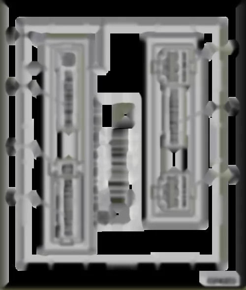
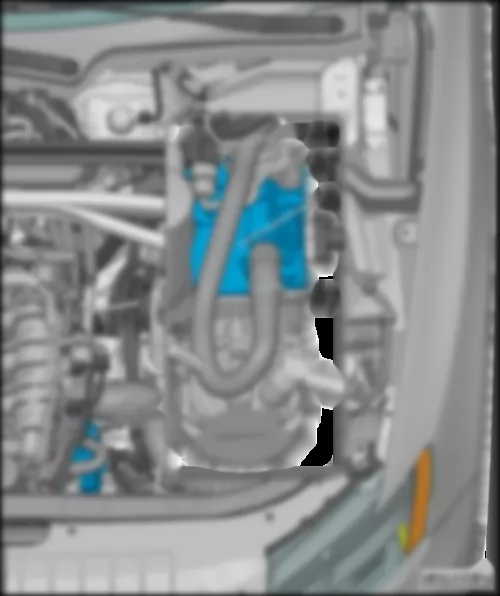
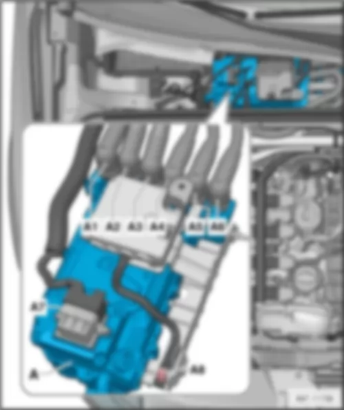
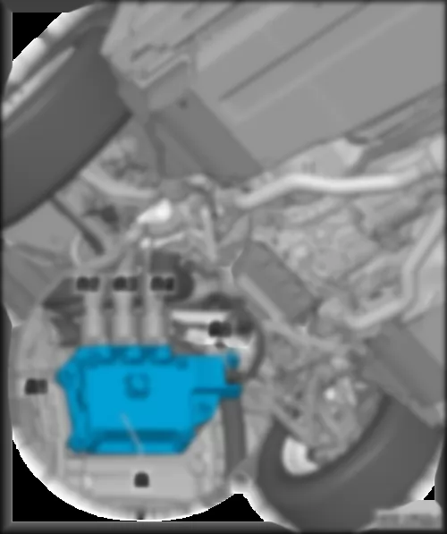
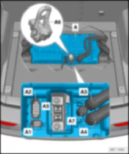
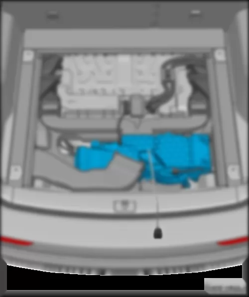
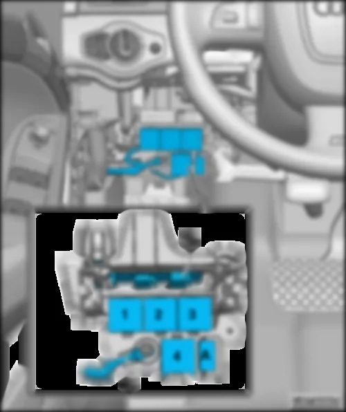
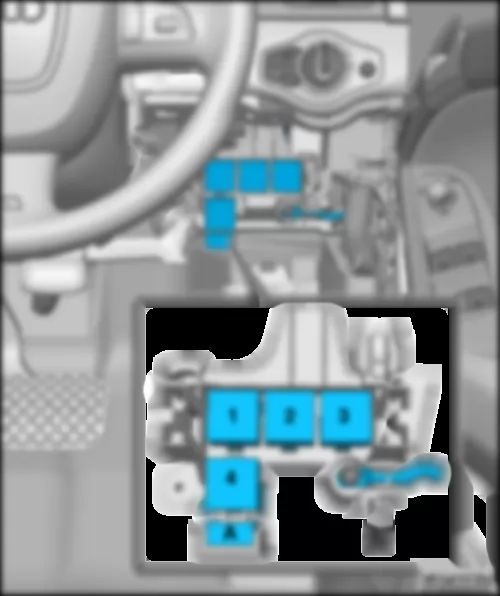
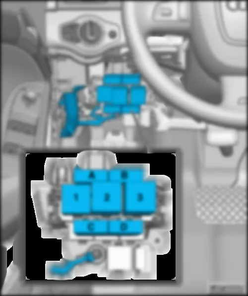
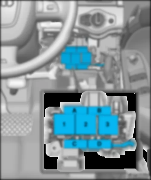
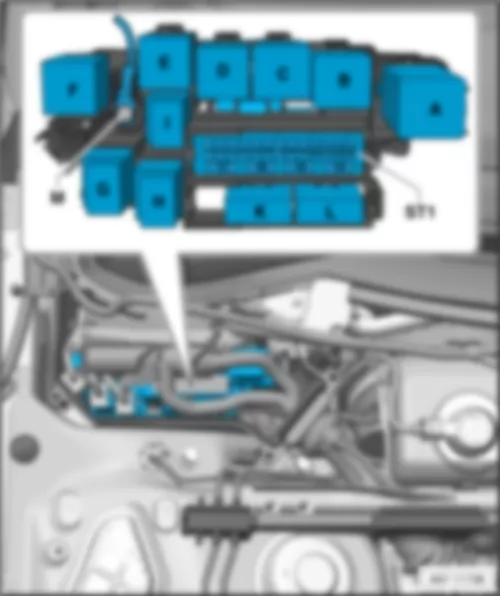
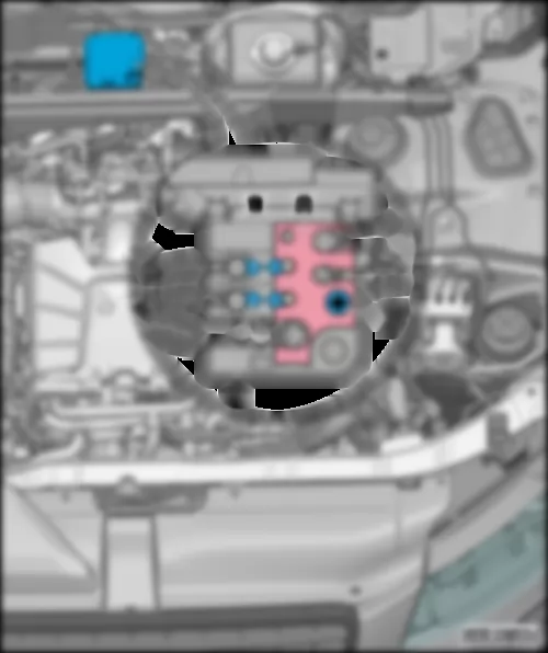
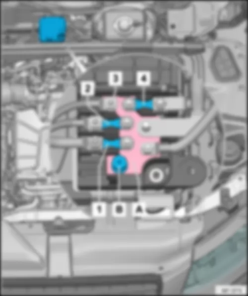
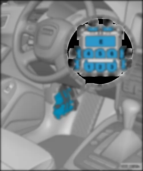
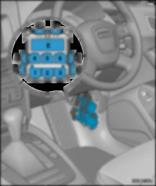
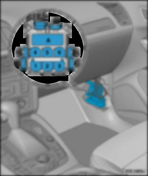
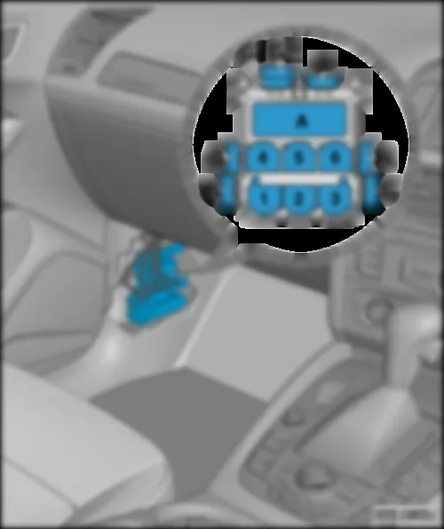
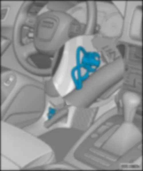
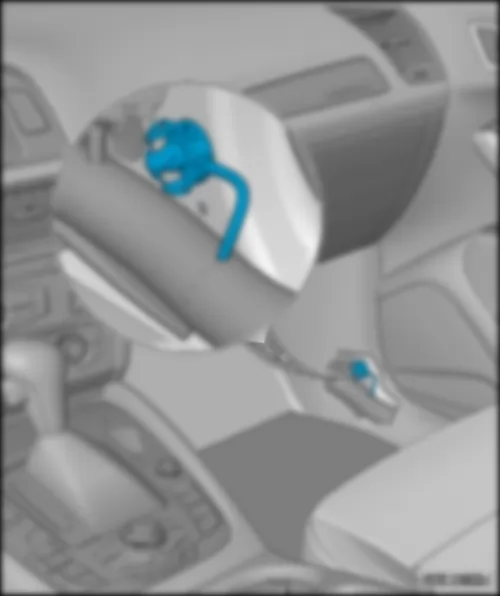
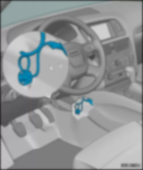
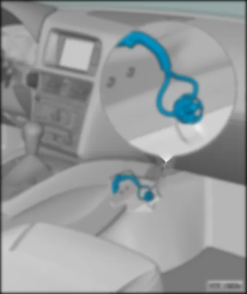
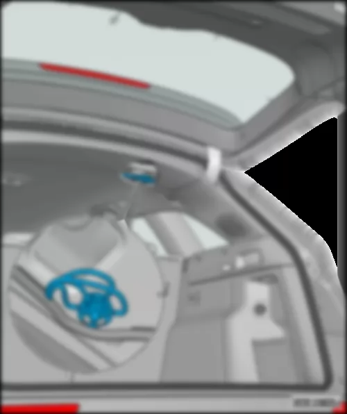
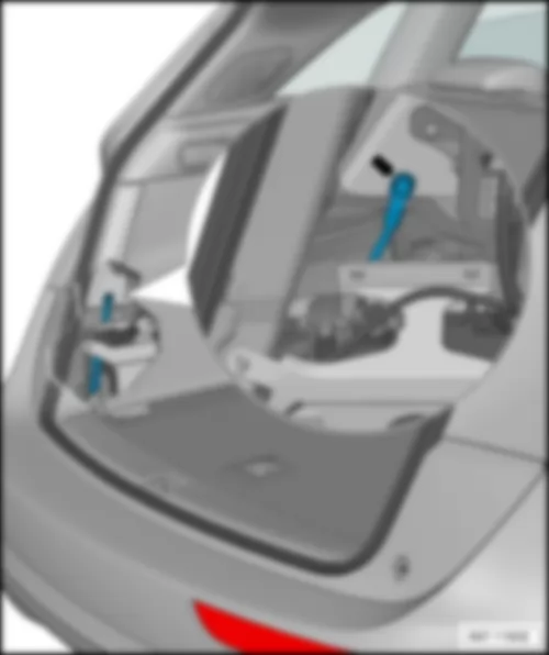
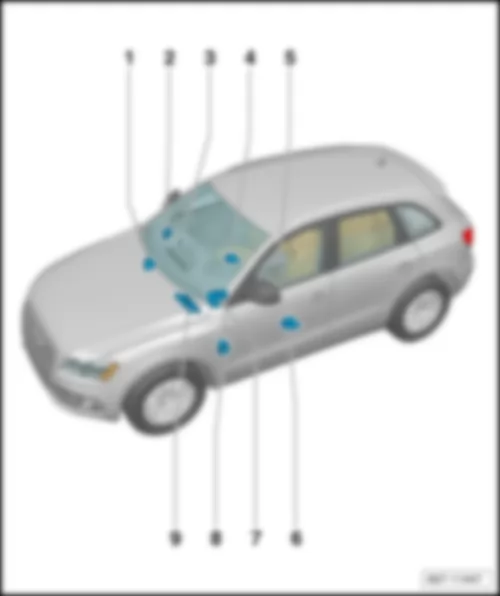
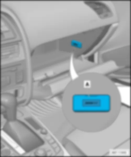
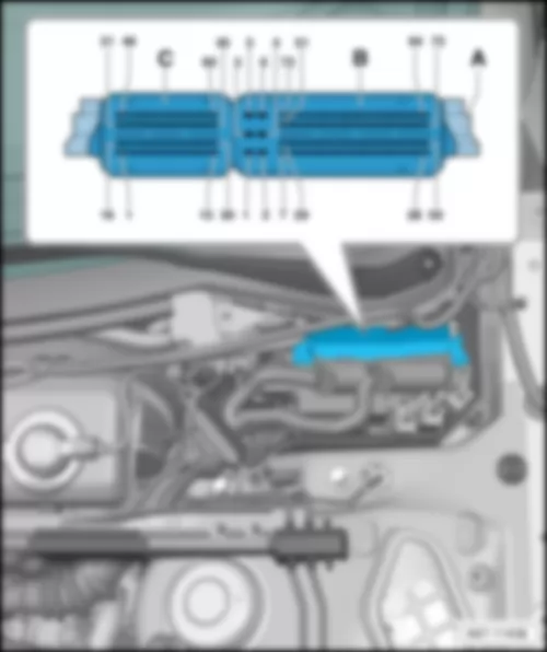
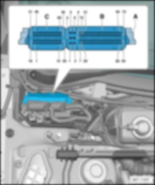
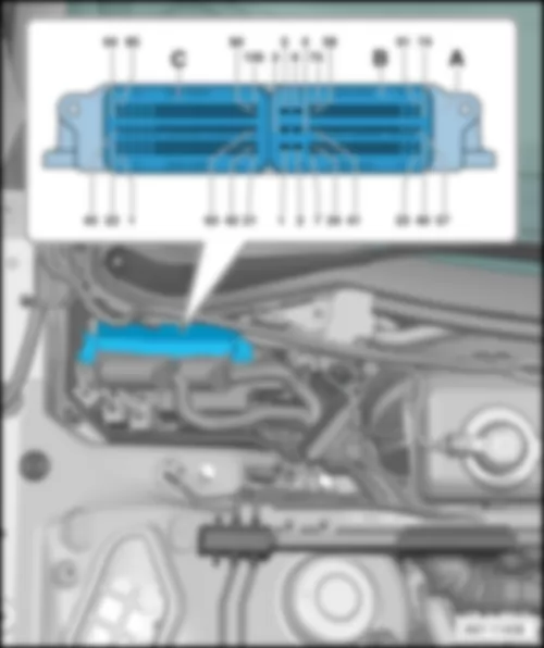
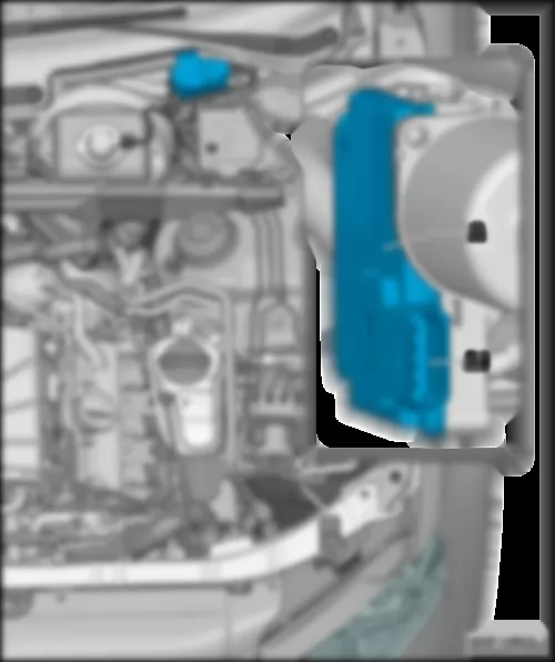
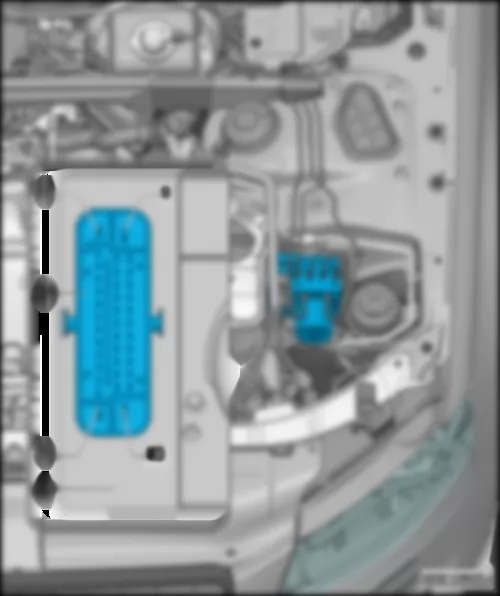
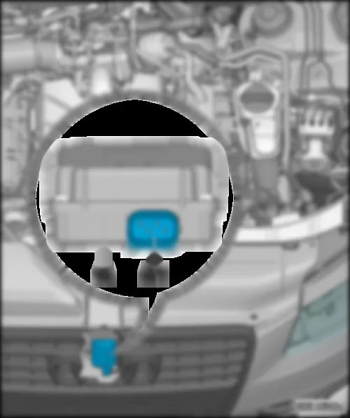
AUDI Q5 2011 Fuse holder A SAFuse holder A -SA- |
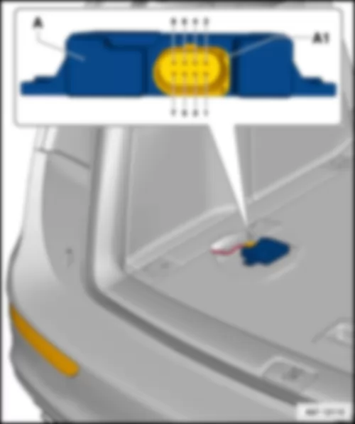
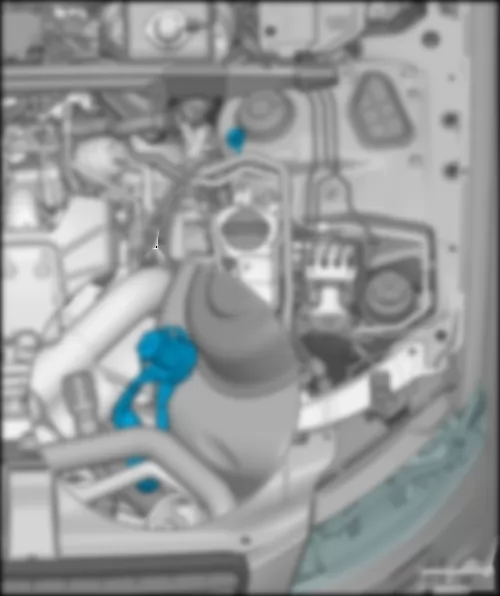
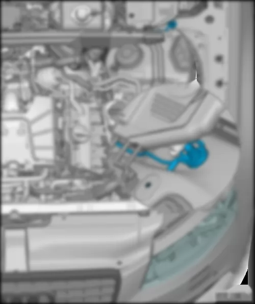
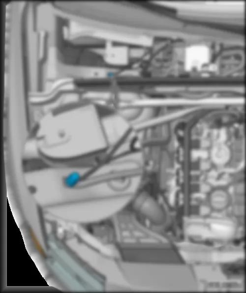
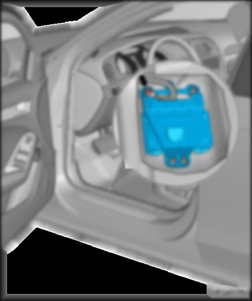
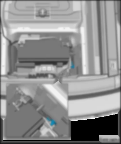
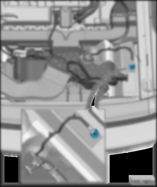
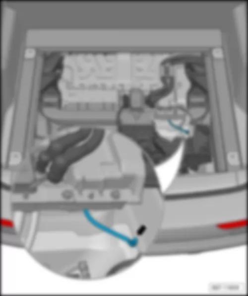
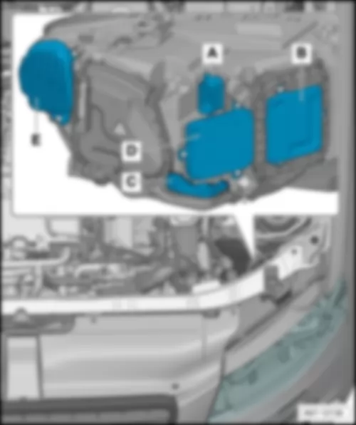
| 1) | | A - | Battery isolation igniter -N253- | | 1 - | Fuse 1 on fuse holder A -SA1- , | | 2 - | Fuse 2 on fuse holder A -SA2- , | | 3 - | Fuse 3 on fuse holder A -SA3- , |
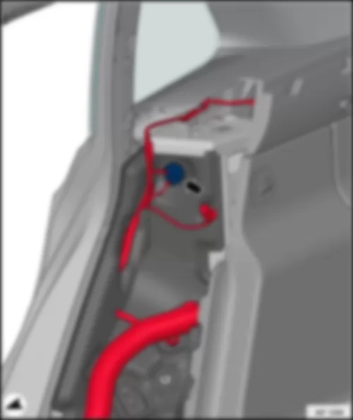
| for models with left-hand drive only | | 3) | not for models with high-voltage system (hybrid) | | 5) | for models with 7-speed dual clutch gearbox only | | 7) | | 110 A | - | Onboard supply
Engine component supply
Reducing agent metering system relay -J963- | 30 | | 2 | - | Fuse 2 on fuse holder A -SA2- | 110 A | - | Onboard supply
Engine component supply
ABS control unit fuse 1 -S123- | 30 | | 3 | - | Fuse 3 on fuse holder A -SA3- | 40 A
50 A
110 A
80 A | - | Option for driving school
Option for hire car
Option for authorities
Mechatronic unit for dual clutch gearbox -J743-
ABS control unit fuse 1 -S123-
ABS control unit fuse 2 -S124-
ABS control unit fuse 3 -S137- | 30 |
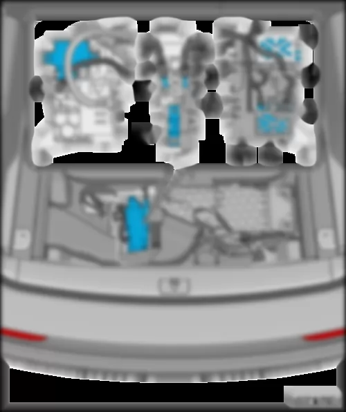
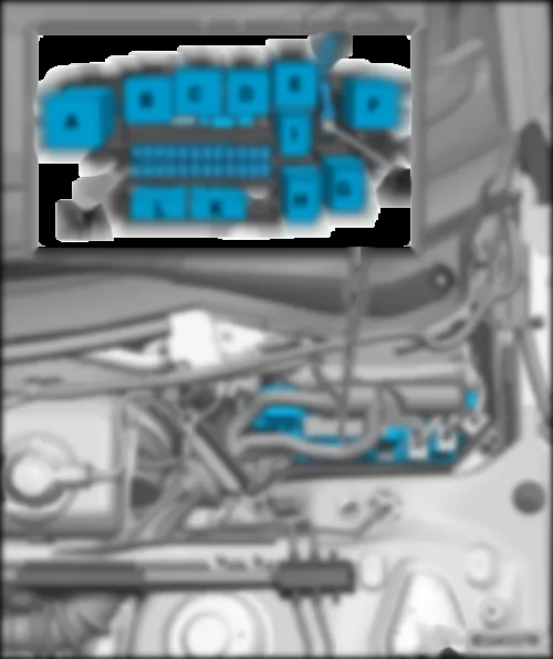
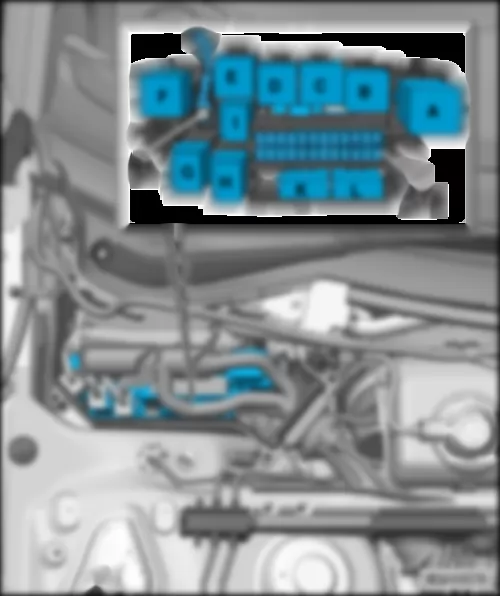
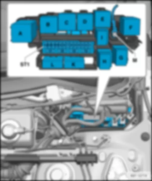
AUDI Q5 2011 Relay/fuse holder B -SB- , up to and including model year 2012 |
| for models with 4-cylinder diesel engine only | | 9) | for models with 4-cylinder petrol engine with high-voltage system (hybrid) only | | 11) | for models with 6-cylinder petrol engine only | Note: | t | Figure shows left-hand drive model. | | t | Fitting location for models with right-hand drive: | | | | | K - | Engine glow plug strip fuse -S39- , 60 A | | K - | Engine glow plug strip fuse -S39- , 80 A | | K - | Secondary air pump fuse -S130- , 50 A | | L - | NOx sender fuse -S360- , 5 A |
| for models with 4-cylinder diesel engine only | | 13) | for models with 4-cylinder petrol engine with high-voltage system (hybrid) only | | | | | K - | Engine glow plug strip fuse -S39- , 60 A | | K - | Engine glow plug strip fuse -S39- , 80 A | | K - | Secondary air pump fuse -S130- , 50 A | | L - | NOx sender fuse -S360- , 5 A |
| for models with 4-cylinder petrol engine (1.8 l TFSI) only | | 17) | for models with 6-cylinder petrol engine (3.2 l FSI) only | | 19) | for models with 4-cylinder diesel engine (2.0 l TDI) only | | 21) | for models with 4-cylinder diesel engine (2.0 l TDI - gen. 2) only | | 23) |
15 A
15 A
15 A
15 A
15 A
15 A
20 A | - | Automatic glow period control unit -J179-
Secondary air pump relay -J299-
Throttle valve module -J338-
Low heat output relay -J359-
High heat output relay -J360-
Charge pressure control solenoid valve -N75-
Heater element for crankcase breather -N79-
Activated charcoal filter solenoid valve 1 -N80-
Secondary air inlet valve -N112-
Left electrohydraulic engine mounting solenoid valve -N144-
Right electrohydraulic engine mounting solenoid valve -N145-
Variable intake manifold changeover valve -N156-
Air filter bypass flap valve -N275-
Fuel pressure regulating valve -N276-
Fuel metering valve -N290-
Injector, cylinder 9 -N299-
Intake manifold flap valve -N316-
Secondary air inlet valve 2 -N320-
Exhaust gas recirculation cooler changeover valve -N345-
Exhaust gas recirculation cooler changeover valve -N428-
Fuel system diagnostic pump -V144- | 87 | | 6 | | Fuse 6 on fuse holder B -SB6- | 15 A | - | Engine control unit -J623- | 87 | | 7 | | Fuse 7 on fuse holder B -SB7- | 10 A
10 A
10 A
10 A
10 A
10 A
15 A
15 A | - | Actuator 1 for camshaft adjustment -F366-
to
actuator 8 for camshaft adjustment -F373-
Actuator 9 for camshaft adjustment -F374-
to
actuator 12 for camshaft adjustment -F377-
Continued coolant circulation relay -J151-
Additional coolant pump relay -J496-
Charge pressure control solenoid valve -N75-
Activated charcoal filter solenoid valve 1 -N80-
Left electrohydraulic engine mounting solenoid valve -N144-
Right electrohydraulic engine mounting solenoid valve -N145-
Camshaft control valve 1 -N205-
Camshaft control valve 2 -N208-
Turbocharger air recirculation valve -N249-
Fuel pressure regulating valve -N276-
Fuel metering valve -N290-
Intake manifold flap valve -N316-
Exhaust camshaft control valve 1 -N318-
Exhaust camshaft control valve 2 -N319-
Climatronic coolant shut-off valve -N422-
Valve for oil pressure control -N428-
Fuel system diagnostic pump -V144-
Charge air cooling pump -V188- | 87 | | 8 | | Fuse 8 on fuse holder B -SB8- | 5 A
10 A
10 A
10 A
20 A
20 A
20 A
20 A | - | Pump for exhaust gas recirculation cooler -V400-
Ignition coil 1 with output stage -N70-
Ignition coil 2 with output stage -N127-
Ignition coil 3 with output stage -N291-
Ignition coil 4 with output stage -N292-
Ignition coil 5 with output stage -N323-
Ignition coil 6 with output stage -N324- | 87 | | 9 | | Fuse 9 on fuse holder B -SB9- | 5 A
15 A
15 A
20 A
20 A
20 A | - | Relay for supplementary fuel pump -J832-
Lambda probe 1 heater after catalytic converter -Z29-
Lambda probe 2 heater after catalytic converter -Z30- | 87 | | 10 | | Fuse 10 on fuse holder B -SB10- | 10 A
15 A
15 A
15 A
15 A
15 A
15 A | - | Lambda probe heater -Z19-
Lambda probe heater 2 -Z28-
Lambda probe 1 heater after catalytic converter -Z29- | 87 | | 11 | | Fuse 11 on fuse holder B -SB11- | 5 A | - | Radiator fan control unit -J293-
Radiator fan control unit 2 -J671- | 87 | | 12 | - | Fuse 12 on fuse holder B -SB12- | 5 A | - | Air mass meter -G70-
Automatic gearbox control unit -J217-
Mechatronic unit for dual clutch gearbox -J743- | 15 |
| Fuses in fuse carrier ST1 on fuse holder B -SB- (black) with high-voltage system (hybrid), up to and including model year 2012 | | K - | Secondary air pump fuse -S130- , 50 A | | L - | Gearbox hydraulic pump relay -J510- , 50 A | | ST1 - | Fuse carrier 1, fuses |
| No. | | Current flow diagram designation | Nominal value | | Function/component | Terminal | | 1 | - | Fuse 1 on fuse holder B -SB1- | 15 A | - | Automatic gearbox control unit -J217-
Mechatronic unit for dual clutch gearbox -J743- | 30 | | 2 | - | Fuse 2 on fuse holder B -SB2- | 5 A | - | Oil level and oil temperature sender -G266- | 87 | | 3 | - | Fuse 3 on fuse holder B -SB3- | 5 A | - | Air mass meter -G70-
Engine control unit -J623-
Power and control electronics for electric drive -JX1- | 87 | | 4 | | Fuse 4 on fuse holder B -SB4- | 5 A | - | Engine control unit -J623- | 30 | | 5 | | Fuse 5 on fuse holder B -SB5- | 10 A | - | Coolant shut-off valve -N82-
Fuel pressure regulating valve -N276- | 87 | | 6 | | Fuse 6 on fuse holder B -SB6- | 15 A | - | Engine control unit -J623- | 87 | | 7 | | Fuse 7 on fuse holder B -SB7- | 15 A | - | Actuator 1 for camshaft adjustment -F366-
to
actuator 8 for camshaft adjustment -F373-
Secondary air pump relay -J299-
Charge pressure control solenoid valve -N75-
Activated charcoal filter solenoid valve 1 -N80-
Secondary air inlet valve -N112-
Left electrohydraulic engine mounting solenoid -N144-
Right electrohydraulic engine mounting solenoid -N145-
Camshaft control valve 1 -N205-
Turbocharger air recirculation valve -N249-
Intake manifold flap valve -N316-
Exhaust flap 1 valve -N321-
Climatronic coolant shut-off valve -N422-
Valve for oil pressure control -N428-
Continued coolant circulation pump -V51-
Coolant pump for high-temperature circuit -V467- | 87 | | 8 | | Fuse 8 on fuse holder B -SB8- | 5 A | - | Power and control electronics for electric drive -JX1- | 30 | | 9 | | Fuse 9 on fuse holder B -SB9- | 5 A | - | Power steering control unit -J500- | 87 | | 10 | | Fuse 10 on fuse holder B -SB10- | 15 A | - | Lambda probe heater -Z19-
Lambda probe 1 heater after catalytic converter -Z29- | 87 | | 11 | | Fuse 11 on fuse holder B -SB11- | 5 A | - | Radiator fan control unit -J293-
Radiator fan -V7-
Radiator fan 2 -V177- | 87 | | 12 | | Fuse 12 on fuse holder B -SB12- | 5 A | - | Automatic gearbox control unit -J217-
Mechatronic unit for dual clutch gearbox -J743- | 87 | | 13 | | Fuse 13 on fuse holder B -SB13- | 5 A | - | Control unit for air conditioning compressor -J842-
Electrical air conditioner compressor -V470- | 87 | | 14 | | Fuse 14 on fuse holder B -SB14- | 20 A | - | Ignition coil 1 with output stage -N70-
Ignition coil 2 with output stage -N127-
Ignition coil 3 with output stage -N291-
Ignition coil 4 with output stage -N292- | 87 | | 15 | | Fuse 15 on fuse holder B -SB15- | | - | not assigned | | | 16 | | Fuse 16 on fuse holder B -SB16- | 5 A | - | Low-temperature circuit coolant pump -V468- | 87 | | 17 | - | Fuse 17 on fuse holder B -SB17- | 5 A | - | Engine control unit -J623- | 50 |
AUDI Q5 2011 Fitting location, relay/fuse holder B -SB- for models with left-hand drive, from model year 2013: |
| In electronics box in plenum chamber, driver side. | | 24) | for models with 6-cylinder diesel engine only | | 26) | for models with 6-cylinder petrol engine only | Note: | t | Figure shows left-hand drive model. | | t | Fitting location for models with right-hand drive: | | | | | K - | Engine glow plug strip fuse -S39- , 60 A | | K - | Engine glow plug strip fuse -S39- , 80 A | | K - | Secondary air pump fuse -S130- , 50 A | | L - | Gearbox hydraulic pump relay -J510- , 50 A | | ST1 - | Fuse carrier 1, fuses |
| for models with 4-cylinder diesel engine only | | 29) | for models with 4-cylinder petrol engine with high-voltage system (hybrid) only | | 31) | for models with 6-cylinder petrol engine only | Note: | t | Figureshowsright-hand drivemodel. | | t | Figure for models with left-hand drive | | | | | K - | Engine glow plug strip fuse -S39- , 60 A | | K - | Engine glow plug strip fuse -S39- , 80 A | | K - | Secondary air pump fuse -S130- , 50 A | | L - | Gearbox hydraulic pump relay -J510- , 50 A | | ST1 - | Fuse carrier 1, fuses |
| Fuses in fuse carrier ST1 on fuse holder B -SB- (black), from model year 2013 | | 32) | for models with 4-cylinder petrol engine with high-voltage system (hybrid) only | | 34) | for models with 4-cylinder diesel engine (2.0 l TDI) only | | 36) | for models with 6-cylinder diesel engine (3.0 l TDI - BIN 5) only | | | | | No. | | Current flow diagram designation | Nominal value | | Function/component | Terminal | | 1 | - | Fuse 1 on fuse holder B -SB1- | 15 A | - | Automatic gearbox control unit -J217-
Mechatronic unit for dual clutch gearbox -J743- | 30 | | 2 | - | Fuse 2 on fuse holder B -SB2- | 5 A | - | Oil level and oil temperature sender -G266- | 87 | | 3 | - | Fuse 3 on fuse holder B -SB3- | 5 A | - | Engine control unit -J623-
Power and control electronics for electric drive -JX1- | 87 | | 4 | | Fuse 4 on fuse holder B -SB4- | 5 A | - | Engine control unit -J623- | 30 | | 5 | | Fuse 5 on fuse holder B -SB5- | 5 A
10 A
| - | Coolant shut-off valve -N82-
Fuel pressure regulating valve -N276-
Air mass meter -G70-
| 87 | | 6 | | Fuse 6 on fuse holder B -SB6- | 15 A | - | Engine control unit -J623- | 87 | | 7 | | Fuse 7 on fuse holder B -SB7- | 10 A
15 A
| - | Actuator 1 for camshaft adjustment -F366-
to
actuator 8 for camshaft adjustment -F373-
Secondary air pump relay -J299-
Charge pressure control solenoid valve -N75-
Activated charcoal filter solenoid valve 1 -N80-
Secondary air inlet valve -N112-
Left electrohydraulic engine mounting solenoid -N144-
Right electrohydraulic engine mounting solenoid -N145-
Camshaft control valve 1 -N205-
Turbocharger air recirculation valve -N249-
Intake manifold flap valve -N316-
Exhaust flap 1 valve -N321-
Climatronic coolant shut-off valve -N422-
Valve for oil pressure control -N428-
Continued coolant circulation pump -V51-
Coolant pump for high-temperature circuit -V467- | 87 | | 8 | | Fuse 8 on fuse holder B -SB8- | 5 A
10 A
15 A | - | Power and control electronics for electric drive -JX1-
NOx sender -G295-
NOx sender 2 -G687-
Control unit for NOx sender -J583-
Control unit for NOx sender 2 -J881-
Brake servo relay -J569- | 30 | | 9 | | Fuse 9 on fuse holder B -SB9- | 5 A | - | Engine control unit -J623- | 87 | | 10 | | Fuse 10 on fuse holder B -SB10- | 10 A
15 A
| - | Lambda probe heater -Z19-
Lambda probe 1 heater after catalytic converter -Z29-
Power steering control unit -J500-
| 87 | | 11 | | Fuse 11 on fuse holder B -SB11- | 5 A | - | Radiator fan control unit -J293-
Radiator fan -V7-
Radiator fan 2 -V177- | 87 | | 12 | | Fuse 12 on fuse holder B -SB12- | 5 A | - | Automatic gearbox control unit -J217-
Mechatronic unit for dual clutch gearbox -J743- | 87 | | 13 | | Fuse 13 on fuse holder B -SB13- | 5 A | - | Control unit for air conditioning compressor -J842-
Electrical air conditioner compressor -V470- | 87 | | 14 | | Fuse 14 on fuse holder B -SB14- | 5 A
20 A
| - | Engine component current supply relay 2 -J976-
Ignition coil 1 with output stage -N70-
Ignition coil 2 with output stage -N127-
Ignition coil 3 with output stage -N291-
Ignition coil 4 with output stage -N292-
Ignition coil 5 with output stage -N323-
Ignition coil 6 with output stage -N324-
Climatronic coolant shut-off valve -N422-
Pump for exhaust gas recirculation cooler -V400- | 87 | | 15 | | Fuse 15 on fuse holder B -SB15- | 5 A | - | Power steering control unit -J500-
Lambda probe heater -Z19-
Lambda probe 1 heater after catalytic converter -Z29-
| 87 | | 16 | | Fuse 16 on fuse holder B -SB16- | 15 A | - | Map-controlled engine cooling system thermostat -F265-
Automatic glow period control unit -J179-
Secondary air pump relay -J299-
Low heat output relay -J359-
High heat output relay -J360-
Additional coolant pump relay -J496-
Gearbox cooling circuit relay -J696-
Charge pressure control solenoid valve -N75-
Heater element for crankcase breather -N79-
Activated charcoal filter solenoid valve 1 -N80-
Secondary air inlet valve -N112-
Left electrohydraulic engine mounting solenoid valve -N144-
Right electrohydraulic engine mounting solenoid valve -N145-
Air filter bypass flap valve -N275-
Secondary air inlet valve 2 -N320-
Exhaust gas recirculation cooler changeover valve -N345-
Valve for oil pressure control -N428-
Coolant valve for gearbox -N488-
Coolant valve for cylinder head -N489-
Actuator for engine temperature regulation -N493-
Charge air cooling pump -V188-
Crankcase breather valve -V546- | 87 | | 17 | - | Fuse 17 on fuse holder B -SB17- | 10 A
15A | - | Coolant pump for low-temperature circuit -V468-
Lambda probe heater -Z19-
Lambda probe 1 heater after catalytic converter -Z29-
| 50 |
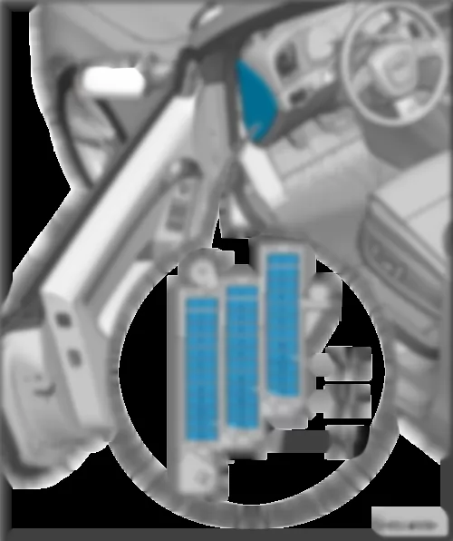
| Fuse holder C -SC- , up to model year 2009 | | Fitting location, fuse holder C -SC- for models with left-hand drive, up to model year 2009: | | Below the dash panel cover, driver side. | Note: | t | Figure shows left-hand drive model. | | t | Figure for models with right-hand drive | | | | | ST1 - | Fuse carrier 1, fuses | | ST2 - | Fuse carrier 2, fuses | | ST3 - | Fuse carrier 3, fuses |
| ST1 - | Fuse carrier 1, fuses | | ST2 - | Fuse carrier 2, fuses | | ST3 - | Fuse carrier 3, fuses |
| Fuses in fuse carrier ST2 on fuse holder C -SC- (brown) | | 38) | for models with diesel engine only | | | | | No. | | Current flow diagram designation | Nominal value | | Function/component | Terminal | | 1 | - | Fuse 1 on fuse holder C -SC1- | 5 A | - | Circulation pump relay -J160- | 87 | | 2 | - | Fuse 2 on fuse holder C -SC2- | 5 A | - | Clutch pedal switch -F36-
Clutch pedal switch for engine start -F194-
Clutch position sender -G476- | 87 | | 3 | - | Fuse 3 on fuse holder C -SC3- | 20 A
25 A | - | Fuel system pressurisation pump -G6-
Fuel pump control unit -J538- | 87 | | 4 | - | Fuse 4 on fuse holder C -SC4- | 5 A | - | Circulation pump relay -J160- | 15 | | 5 | - | Fuse 5 on fuse holder C -SC5- | 30 A | - | Onboard supply control unit -J519- | 30 | | 6 | - | Fuse 6 on fuse holder C -SC6- | 10 A | - | ABS control unit -J104- | 30 | | 7 | - | Fuse 7 on fuse holder C -SC7- | 25 A | - | Horn relay -J413- | 30 | | 8 | - | Fuse 8 on fuse holder C -SC8- | 30 A | - | Driver door control unit -J386-
Rear left door control unit -J388- | 30 | | 9 | - | Fuse 9 on fuse holder C -SC9- | 30 A | - | Wiper motor control unit -J400- | 30 | | 10 | - | Fuse 10 on fuse holder C -SC10- | 25 A | - | ABS control unit -J104- | 30 | | 11 | - | Fuse 11 on fuse holder C -SC11- | 15 A | - | Driver door control unit -J386-
Rear left door control unit -J388- | 30 | | 12 | - | Fuse 12 on fuse holder C -SC12- | 5 A | - | Rain and light sensor -G397- | 30 |
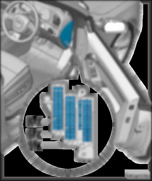
AUDI Q5 2011 | Fuse holder C -SC- , from model year 2010 | | Fitting location, fuse holder C -SC- for models with left-hand drive, from model year 2010: | | Below the dash panel cover, driver side. | Note: | t | Figure shows left-hand drive model. | | t | Figure for models with right-hand drive | | | | | ST1 - | Fuse carrier 1, fuses | | ST2 - | Fuse carrier 2, fuses | | ST3 - | Fuse carrier 3, fuses |
| ST1 - | Fuse carrier 1, fuses | | ST2 - | Fuse carrier 2, fuses | | ST3 - | Fuse carrier 3, fuses |
| Fuses in fuse carrier ST2 on fuse holder C -SC- (brown) | | 40) | for models with 4-cylinder petrol engine with high-voltage system (hybrid) only | | 42) | for models with diesel engine (with J538) only | | 44) | for models without seat ventilation only | | 46) |
25 A
25 A
25 A | - | Fuel system pressurisation pump -G6-
Fuel pump control unit -J538- | 87 | | 4 | - | Fuse 4 on fuse holder C -SC4- | 10 A
25 A | - | Vacuum pump relay -J318-
Circulation pump relay -J160-
Pump for reducing agent -V437- | 15
30 | | 5 | - | Fuse 5 on fuse holder C -SC5- | 15 A
30 A | - | Onboard supply control unit -J519- | 30 | | 6 | - | Fuse 6 on fuse holder C -SC6- | 5 A
10 A | - | ABS control unit -J104- | 30 | | 7 | - | Fuse 7 on fuse holder C -SC7- | 25 A | - | Horn relay -J413- | 30 | | 8 | - | Fuse 8 on fuse holder C -SC8- | 30 A | - | Left doors | 30 | | 9 | - | Fuse 9 on fuse holder C -SC9- | 30 A | - | Wiper motor control unit -J400- | 30 | | 10 | - | Fuse 10 on fuse holder C -SC10- | 25 A | - | ABS control unit -J104- | 30 | | 11 | - | Fuse 11 on fuse holder C -SC11- | 15 A | - | Left doors | 30 | | 12 | - | Fuse 12 on fuse holder C -SC12- | 5 A | - | Rain and light sensor -G397- | 30 |
AUDI Q5 2011 | Fuse holder C -SC- , from model year 2013 | | Fitting location, fuse holder C -SC- for models with left-hand drive, from model year 2013: | | Below the dash panel cover, driver side. | Note: | t | Figure shows left-hand drive model. | | t | Figure for models with right-hand drive | | | | | ST1 - | Fuse carrier 1, fuses | | ST2 - | Fuse carrier 2, fuses | | ST3 - | Fuse carrier 3, fuses |
| ST1 - | Fuse carrier 1, fuses | | ST2 - | Fuse carrier 2, fuses | | ST3 - | Fuse carrier 3, fuses |
| Fuses in fuse carrier ST2 on fuse holder C -SC- (brown) | | 47) | for models with seat ventilation only | | | | | No. | | Current flow diagram designation | Nominal value | | Function/component | Terminal | | 1 | - | Fuse 1 on fuse holder C -SC1- | 5 A | - | Exhaust flap valve -N220- | 87 | | 2 | - | Fuse 2 on fuse holder C -SC2- | 5 A | - | Brake light switch -F- | 87 | | 3 | - | Fuse 3 on fuse holder C -SC3- | 25 A | - | Fuel pump control unit -J538- | 87 | | 4 | - | Fuse 4 on fuse holder C -SC4- | 5 A
25 A | - | Clutch position sender -G476-
Pressure sender for reducing agent metering system -G686-
Control unit for reducing agent metering system -J880-
Pump for reducing agent -V437-
Heater for reducing-agent pump -Z103-
Vacuum pump relay -J318- | 87 | | 5 | - | Fuse 5 on fuse holder C -SC5- | 15 A
30 A | - | Onboard supply control unit -J519-
Control unit for front left seat ventilation -J800- | 30 | | 6 | - | Fuse 6 on fuse holder C -SC6- | 5 A | - | ABS control unit -J104- | 30 | | 7 | - | Fuse 7 on fuse holder C -SC7- | 15 A | - | Treble horn -H2-
Bass horn -H7-
Horn relay -J413- | 30 | | 8 | - | Fuse 8 on fuse holder C -SC8- | 30 A | - | Front left door | 30 | | 9 | - | Fuse 9 on fuse holder C -SC9- | 30 A | - | Wiper motor control unit -J400- | 30 | | 10 | - | Fuse 10 on fuse holder C -SC10- | 25 A | - | ABS control unit -J104- | 30 | | 11 | - | Fuse 11 on fuse holder C -SC11- | 30 A | - | Rear left door | 30 | | 12 | - | Fuse 12 on fuse holder C -SC12- | 5 A | - | Rain and light sensor -G397- | 30 |
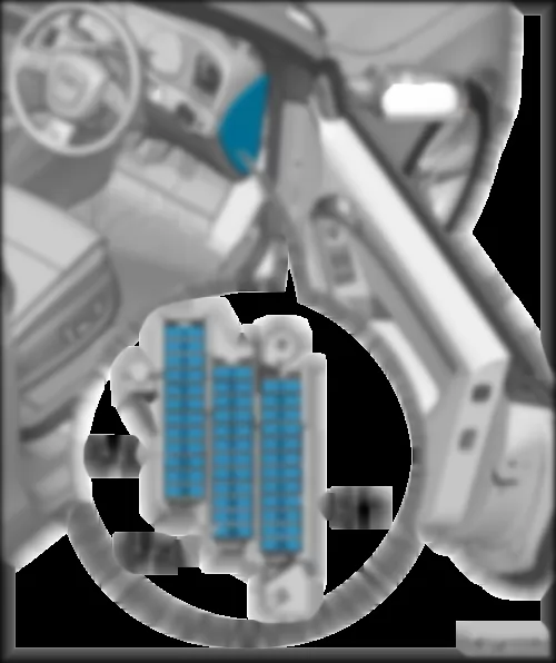
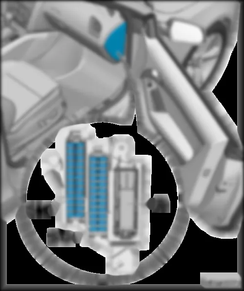
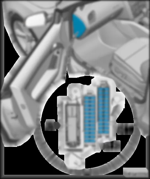
AUDI Q5 2011 Fuse holder D SD | Fuse holder D -SD- | | Fitting location, fuse holder D -SD- for models with left-hand drive: | | Below the dash panel cover, front passenger side. | Note: | t | Figure shows left-hand drive model. | | t | Figure for models with right-hand drive | | | | | ST1 - | Fuse carrier 1, fuses | | ST2 - | Fuse carrier 2, fuses | | A - | 46-pin connector, black, CAN disconnector, dash panel -T46s- |
| ST1 - | Fuse carrier 1, fuses | | ST2 - | Fuse carrier 2, fuses | | A - | 46-pin connector, black, CAN disconnector, dash panel -T46s- |
| for models with 4-cylinder petrol engine with high-voltage system (hybrid) only | | | | | No. | | Current flow diagram designation | Nominal value | | Function/component | Terminal | | 1 | - | Fuse 1 on fuse holder D -SD1- | | - | not assigned | | | 2 | - | Fuse 2 on fuse holder D -SD2- | | - | not assigned | | | 3 | - | Fuse 3 on fuse holder D -SD3- | | - | not assigned | | | 4 | - | Fuse 4 on fuse holder D -SD4- | | - | not assigned | | | 5 | - | Fuse 5 on fuse holder D -SD5- | 5 A | - | Steering column electronics control unit -J527- | 15 | | 6 | - | Fuse 6 on fuse holder D -SD6- | | - | not assigned | | | 7 | - | Fuse 7 on fuse holder D -SD7- | 5 A | - | 16-pin connector -T16- , diagnostic connector | 15 | | 8 | - | Fuse 8 on fuse holder D -SD8- | 5 A | - | Data bus diagnostic interface -J533- | 15 | | 9 | - | Fuse 9 on fuse holder D -SD9- | 5 A | - | Low heat output relay -J359-
Coolant heater elements relay 2 -J390-
Auxiliary air heater control unit -J604- | 15 | | 10 | - | Fuse 10 on fuse holder D -SD10- | | - | not assigned | | | 11 | - | Fuse 11 on fuse holder D -SD11- | | - | not assigned | | | 12 | - | Fuse 12 on fuse holder D -SD12- | | - | not assigned | |
| for models with radio (CAN) with external amplifier only | | 51) | for models with radio chorus and sound system Basic (from November 2009) only | | 53) |
5 A
20 A
20 A | - | Display unit for front information display and operating unit control unit -J685-
Control unit 1 for information electronics -J794-
Radio -R- | 30 | | 4 | - | Fuse 4 on fuse holder D -SD4- | 5 A | - | Control unit in dash panel insert -J285- | 30 | | 5 | - | Fuse 5 on fuse holder D -SD5- | 5 A | - | Data bus diagnostic interface -J533- | 30 | | 6 | - | Fuse 6 on fuse holder D -SD6- | 5 A | - | Entryandstartauthorisationswitch -E415- | 30 | | 7 | - | Fuse 7 on fuse holder D -SD7- | 5A | - | Light switch -E1- | | | 8 | - | Fuse 8 on fuse holder D -SD8- | 40 A | - | Fresh air blower control unit -J126- | 30 | | 9 | - | Fuse 9 on fuse holder D -SD9- | 5 A | - | Control unit for electronic steering column lock -J764- | 30 | | 10 | - | Fuse 10 on fuse holder D -SD10- | 10 A | - | Climatronic control unit -J255- | 30 | | 11 | - | Fuse 11 on fuse holder D -SD11- | 10 A | - | 16-pin connector -T16- , diagnostic connector | 30 | | 12 | - | Fuse 12 on fuse holder D -SD12- | 5 A | - | Steering column electronics control unit -J527- | 30 |
AUDI Q5 2011 Relay/fuse holder F -SF- , up to model year 2009 |
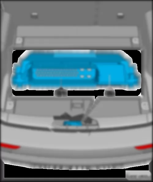
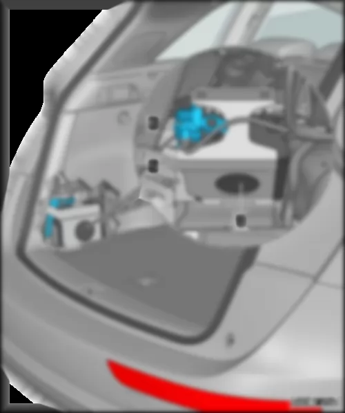
| Fitting location, relay/fuse holder F -SF- , up to model year 2009 | | In luggage compartment, behind side trim on right. | | | | | ST1 - | Fuse carrier 1, fuses | | ST2 - | Fuse carrier 2, fuses | | ST3 - | Fuse carrier 3, fuses | | ST4 - | Fuse carrier 4, fuses | | ST5 - | Fuse carrier 5, fuses | | H - | Heated rear window fuse -S41- |
| Fuses in fuse carrier ST2 on fuse holder F -SF- (black) | | No. | | Current flow diagram designation | Nominal value | | Function/component | Terminal | | 1 | - | Fuse 1 on fuse holder F -SF1- | 5 A | - | Tyre Pressure Monitoring System control unit -J502- | 30 | | 2 | - | Fuse 2 on fuse holder F -SF2- | 15 A | - | Trailer detector control unit -J345- | 30 | | 3 | - | Fuse 3 on fuse holder F -SF3- | 20 A | - | Trailer detector control unit -J345- | 30 | | 4 | - | Fuse 4 on fuse holder F -SF4- | 20 A | - | Trailer detector control unit -J345- | 30 | | 5 | - | Fuse 5 on fuse holder F -SF5- | 5 A | - | Electromechanical parking brake button -E538- | 30 | | 6 | - | Fuse 6 on fuse holder F -SF6- | 15 A | - | Electronically controlled damping control unit -J250- | 30 | | 7 | - | Fuse 7 on fuse holder F -SF7- | 30 A | - | Control unit for electromechanical parking brake -J540- | 30 | | 8 | - | Fuse 8 on fuse holder F -SF8- | 30 A | - | Convenience system central control unit -J393- | 30 | | 9 | - | Fuse 9 on fuse holder F -SF9- | 35 A | - | All-wheel drive control unit -J492- | 30 | | 10 | - | Fuse 10 on fuse holder F -SF10- | 30 A | - | Convenience system central control unit -J393- | 30 | | 11 | - | Fuse 11 on fuse holder F -SF11- | 20 A | - | Convenience system central control unit -J393- | 30 | | 12 | - | Fuse 12 on fuse holder F -SF12- | 5 A | - | Interface control unit for vehicle location system -J843- | 30 |
| Fuses in fuse carrier ST4 on fuse holder F -SF- (red) | | No. | | Current flow diagram designation | Nominal value | | Function/component | Terminal | | 1 | - | Fuse 1 on fuse holder F -SF1- | 15 A | - | 12 V socket 2 -U18- | 87 | | 2 | - | Fuse 2 on fuse holder F -SF2- | 15 A | - | 12 V socket -U5- | 87 | | 3 | - | Fuse 3 on fuse holder F -SF3- | 15 A | - | 12 V socket 3 -U19- | 87 | | 4 | - | Fuse 4 on fuse holder F -SF4- | 15 A | - | Cigarette lighter -U1- | 87 | | 5 | - | Fuse 5 on fuse holder F -SF5- | 5 A | - | Park assist steering control unit -J791- | 15 | | 6 | - | Fuse 6 on fuse holder F -SF6- | 5 A | - | 18-pin connector, black -T18a- | 15 | | 7 | - | Fuse 7 on fuse holder F -SF7- | 5 A | - | Adaptive cruise control unit -J428- | 15 | | 8 | - | Fuse 8 on fuse holder F -SF8- | 15 A | - | Rear window wiper motor -V12- | 15 | | 9 | - | Fuse 9 on fuse holder F -SF9- | 5 A | - | Auto-hold button -E540- | 15 | | 10 | - | Fuse 10 on fuse holder F -SF10- | 5 A | - | Lane change assist control unit 2 -J770- | 15 | | 11 | - | Fuse 11 on fuse holder F -SF11- | 5 A | - | Heated rear left seat switch with regulator -E128-
Heated rear right seat switch with regulator -E129- | 15 | | 12 | - | Fuse 12 on fuse holder F -SF12- | 5 A | - | Hazard warning light switch -E3-
Airbag control unit -J234-
Seat occupied recognition control unit -J706-Front passenger side airbag deactivated warning lamp -K145- | 15 |
| for civil vehicles: NEF version (F4Z) only | | 55) |
25 A | - | Signal system control unit -J616- | 30 | | 4 | - | Fuse 4 on fuse holder F -SF4- | 15 A | - | Signal system control unit -J616- | 30 | | 5 | - | Fuse 5 on fuse holder F -SF5- | 5 A
15 A | - | Operating unit for special signals -E507-
Signal system control unit -J616- | 30 | | 6 | - | Fuse 6 on fuse holder F -SF6- | 10 A | - | Operating unit for special signals -E507-
Signal system control unit -J616-
Tachograph control unit -J621-
3-pin connector -T3d-
Accident data recorder | 15 | | 7 | - | Fuse 7 on fuse holder F -SF7- | 20 A | - | Special vehicle control unit -J608- | 30 | | 8 | - | Fuse 8 on fuse holder F -SF8- | 10 A | - | Accident data recorder | 30 | | 9 | - | Fuse 9 on fuse holder F -SF9- | 10 A | - | 12 V socket 4 -U20- | 30 | | 10 | - | Fuse 10 on fuse holder F -SF10- | 10 A | - | Two-way radio voltage relay -J84- | 30 | | 11 | - | Fuse 11 on fuse holder F -SF11- | 10 A | - | Two-way radio voltage relay -J84- | 30 | | 12 | - | Fuse 12 on fuse holder F -SF12- | | - | not assigned | |
AUDI Q5 2011 | Relay/fuse holder F -SF- , from model year 2010 | | Fitting location, relay/fuse holder F -SF- , from model year 2010 | | In luggage compartment, behind side trim on right. | | | | | H - | Heated rear window fuse -S41- |
| nur für zivile Einsatzfahrzeuge: NEF - Ausführung (F4Z) | | 57) |
25 A | - | Signal system control unit -J616- | 30 | | 4 | - | Fuse 4 on fuse holder F -SF4- | 15 A | - | Signal system control unit -J616- | 30 | | 5 | - | Fuse 5 on fuse holder F -SF5- | 5 A
15 A | - | Operating unit for special signals -E507-
Signal system control unit -J616- | 30 | | 6 | - | Fuse 6 on fuse holder F -SF6- | 3 A | - | Operating unit for special signals -E507-
Signal system control unit -J616-
Tachograph control unit -J621-
3-pin connector -T3d-
Accident data recorder | 15 | | 7 | - | Fuse 7 on fuse holder F -SF7- | 20 A | - | Special vehicle control unit -J608- | 30 | | 8 | - | Fuse 8 on fuse holder F -SF8- | 10 A | - | Accident data recorder | 30 | | 9 | - | Fuse 9 on fuse holder F -SF9- | 10 A | - | 12 V socket 4 -U20- | 30 | | 10 | - | Fuse 10 on fuse holder F -SF10- | 10 A | - | Two-way radio voltage relay -J84- | 30 | | 11 | - | Fuse 11 on fuse holder F -SF11- | 10 A | - | Two-way radio voltage relay -J84- | 30 | | 12 | - | Fuse 12 on fuse holder F -SF12- | | - | not assigned | |
| for models with 4-cylinder petrol engine with high-voltage system (hybrid) only | | | | | No. | | Current flow diagram designation | Nominal value | | Function/component | Terminal | | 1 | - | Fuse 1 on fuse holder F -SF1- | 30 A | - | Rear lid control unit 2 -J756- | 30 | | 2 | - | Fuse 2 on fuse holder F -SF2- | 15 A | - | Trailer detector control unit -J345- | 30 | | 3 | - | Fuse 3 on fuse holder F -SF3- | 20 A | - | Trailer detector control unit -J345- | 30 | | 4 | - | Fuse 4 on fuse holder F -SF4- | 20 A | - | Trailer detector control unit -J345- | 30 | | 5 | - | Fuse 5 on fuse holder F -SF5- | 5 A | - | Auto-hold button -E540- | 30 | | 6 | - | Fuse 6 on fuse holder F -SF6- | 15 A | - | Electronically controlled damping control unit -J250- | 30 | | 7 | - | Fuse 7 on fuse holder F -SF7- | 30 A | - | Control unit for electromechanical parking brake -J540- | 30 | | 8 | - | Fuse 8 on fuse holder F -SF8- | 30 A | - | Convenience system central control unit -J393- | 30 | | 9 | - | Fuse 9 on fuse holder F -SF9- | 5 A
35 A | - | All-wheel drive control unit -J492-
Tyre Pressure Monitoring System control unit -J502- | 30 | | 10 | - | Fuse 10 on fuse holder F -SF10- | 30 A | - | Convenience system central control unit -J393- | 30 | | 11 | - | Fuse 11 on fuse holder F -SF11- | 20 A | - | Convenience system central control unit -J393- | 30 | | 12 | - | Fuse 12 on fuse holder F -SF12- | 5 A | - | Interface control unit for vehicle location system -J843-
Control unit for fuel tank leak detection -J909-
Fuel system diagnostic pump -V144- | 30 |
| for models with 4-cylinder petrol engine with high-voltage system (hybrid) only | | | | | No. | | Current flow diagram designation | Nominal value | | Function/component | Terminal | | 1 | - | Fuse 1 on fuse holder F -SF1- | 30 A | - | Rear lid control unit -J605- | 30 | | 2 | - | Fuse 2 on fuse holder F -SF2- | 15 A | - | Control unit for front right seat ventilation -J799- | 30 | | 3 | - | Fuse 3 on fuse holder F -SF3- | 15 A
40 A | - | Voltage stabilizer -J532-
Battery regulation control unit -J840- | 30 | | 4 | - | Fuse 4 on fuse holder F -SF4- | 40 A | - | Voltage stabilizer -J532-
Fan enabling relay -J937- | 30 | | 5 | - | Fuse 5 on fuse holder F -SF5- | | - | not assigned | | | 6 | - | Fuse 6 on fuse holder F -SF6- | 30 A | - | Auxiliary heater control unit -J364- | 30 | | 7 | - | Fuse 7 on fuse holder F -SF7- | 30 A | - | Control unit for electromechanical parking brake -J540- | 30 | | 8 | - | Fuse 8 on fuse holder F -SF8- | 30 A | - | Heated rear left seat switch with regulator -E128-
Heated rear right seat switch with regulator -E129- | 30 | | 9 | - | Fuse 9 on fuse holder F -SF9- | 30 A | - | Right doors | 30 | | 10 | - | Fuse 10 on fuse holder F -SF10- | 5 A | - | Remote control receiver for auxiliary heater -R64- | 30 | | 11 | - | Fuse 11 on fuse holder F -SF11- | 15 A | - | Right doors | 30 | | 12 | - | Fuse 12 on fuse holder F -SF12- | 30 A | - | Control unit for reducing agent metering system -J880- | 30 |
| Fuses in fuse carrier ST5 on fuse holder F -SF- (black) | | 60) | applicable up to April 2010 | | 62) |
30 A | - | Digital sound package control unit -J525-
Radio -R- | 30 | | 4 | - | Fuse 4 on fuse holder F -SF4- | 7.5 A | - | Control unit 1 for information electronics -J794- | 30 | | 5 | - | Fuse 5 on fuse holder F -SF5- | 5 A
7.5 A | - | Radio -R-
Telephone transmitter and receiver unit -R36-
TV tuner -R78-
Aerial amplifier for mobile telephone -R86-
Telephone bracket -R126-
18-pin connector, black -T18a- | 30 | | 6 | - | Fuse 6 on fuse holder F -SF6- | 5 A | - | Reversing camera system control unit -J772- | 30 | | 7 | - | Fuse 7 on fuse holder F -SF7- | 5 A | - | Aerial amplifier for mobile telephone -R86- | 30 | | 8 | - | Fuse 8 on fuse holder F -SF8- | 7.5 A | - | Battery regulation control unit -J840- | 15 | | 9 | - | Fuse 9 on fuse holder F -SF9- | | - | not assigned | | | 10 | - | Fuse 10 on fuse holder F -SF10- | | - | not assigned | | | 11 | - | Fuse 11 on fuse holder F -SF11- | | - | not assigned | | | 12 | - | Fuse 12 on fuse holder F -SF12- | | - | not assigned | |
AUDI Q5 2011 | Relay/fuse holder F -SF- , from model year 2013 | | Fitting location, relay/fuse holder F -SF- , from model year 2013 | | In luggage compartment, behind side trim on right. | | | | | H - | Heated rear window fuse -S41- |
| for civil vehicles: NEF version (F4Z) only | | 64) |
25 A | - | Footwell light switch -E295-
Warning buzzer switch -E296-
Special vehicle control unit -J608-
Signal system control unit -J616- | 30 | | 4 | - | Fuse 4 on fuse holder F -SF4- | 15 A | - | Pedal switch for warning buzzer on front passenger side -F349-
Buzzer and gong -H3- | 30 | | 5 | - | Fuse 5 on fuse holder F -SF5- | 5 A
15 A | - | Operating unit for special signals -E507-
Signal system control unit -J616- | 30 | | 6 | - | Fuse 6 on fuse holder F -SF6- | 3 A | - | Operating unit for special signals -E507-
Signal system control unit -J616-
Tachograph control unit -J621-
3-pin connector -T3d-
Accident data memory -J754- | 15 | | 7 | - | Fuse 7 on fuse holder F -SF7- | 20 A | - | Special vehicle control unit -J608- | 30 | | 8 | - | Fuse 8 on fuse holder F -SF8- | 10 A | - | Accident data memory -J754- | 30 | | 9 | - | Fuse 9 on fuse holder F -SF9- | 10 A | - | 12 V socket 4 -U20- | 30 | | 10 | - | Fuse 10 on fuse holder F -SF10- | 10 A | - | Two-way radio voltage relay -J84- , up to model year 2013
Flashing lights relay -J630-
Left flashing light -M47-
Right flashing light -M48- | 30 | | 11 | - | Fuse 11 on fuse holder F -SF11- | 10 A | - | Two-way radio voltage relay 2 -J888-
Two-way radio -R8- | 30 | | 12 | - | Fuse 12 on fuse holder F -SF12- | | - | not assigned | |
| Fuses in fuse carrier ST3 on fuse holder F -SF- (brown) | | No. | | Current flow diagram designation | Nominal value | | Function/component | Terminal | | 1 | - | Fuse 1 on fuse holder F -SF1- | 30 A | - | Rear lid control unit -J605- | 30 | | 2 | - | Fuse 2 on fuse holder F -SF2- | 20 A | - | Relay for power sockets -J807-
Cigarette lighter -U1-
12 V socket -U5-
DC/AC converter with socket, 12 V - 230 V -U13-
12 V socket 2 -U18-
12 V socket 3 -U19- | 30 | | 3 | - | Fuse 3 on fuse holder F -SF3- | 40 A | - | Voltage stabilizer -J532- | 30 | | 4 | - | Fuse 4 on fuse holder F -SF4- | 30 A | - | Voltage stabilizer -J532-
Radio -R-
Digital sound package control unit -J525- | 30 | | 5 | - | Fuse 5 on fuse holder F -SF5- | 25 A | - | DC/AC converter with socket, 12 V - 230 V -U13- | 30 | | 6 | - | Fuse 6 on fuse holder F -SF6- | 30 A | - | Auxiliary heater control unit -J364- | 30 | | 7 | - | Fuse 7 on fuse holder F -SF7- | 30 A | - | Control unit for electromechanical parking brake -J540- | 30 | | 8 | - | Fuse 8 on fuse holder F -SF8- | 30 A | - | Heated rear left seat switch with regulator -E128-
Heated rear right seat switch with regulator -E129- | 30 | | 9 | - | Fuse 9 on fuse holder F -SF9- | 30 A | - | Front right door | 30 | | 10 | - | Fuse 10 on fuse holder F -SF10- | 5 A | - | Remote control receiver for auxiliary heater -R64- | 30 | | 11 | - | Fuse 11 on fuse holder F -SF11- | 30 A | - | Rear right door | 30 | | 12 | - | Fuse 12 on fuse holder F -SF12- | 5 A | - | Telephone transmitter and receiver unit -R36-
Aerial amplifier for mobile telephone -R86-
Telephone bracket -R126- | 30 |
| Fuses in fuse carrier ST5 on fuse holder F -SF- (black) | | 65) | for models with SCR system only | | 67) |
Automatic anti-dazzle interior mirror -Y7- | 30 | | 3 | - | Fuse 3 on fuse holder F -SF3- | 30 A | - | Supply, fuse carrier 2 -ST2-Fuse 1 on fuse holder D -SD1- to fuse 4 on fuse holder D -SD4- | 30 | | 4 | - | Fuse 4 on fuse holder F -SF4- | 7.5 A | - | Control unit 1 for information electronics -J794- | 30 | | 5 | - | Fuse 5 on fuse holder F -SF5- | 5 A | - | Chip card reader control unit -J676-
Radio -R-
TV tuner -R78- | 30 | | 6 | - | Fuse 6 on fuse holder F -SF6- | 5 A | - | Reversing camera system control unit -J772- | 30 | | 7 | - | Fuse 7 on fuse holder F -SF7- | 30 A | - | Heated rear window relay -J9-
Heated rear window -Z1- | 30 | | 8 | - | Fuse 8 on fuse holder F -SF8- | 5 A | - | Preparation for multimedia system:
2-pin connector in driver seat backrest -T2dy-
2-pin connector in front passenger seat backrest -T2dz- | 30 | | 9 | - | Fuse 9 on fuse holder F -SF9- | | - | not assigned | | | 10 | - | Fuse 10 on fuse holder F -SF10- | | - | not assigned | | | 11 | - | Fuse 11 on fuse holder F -SF11- | 30 A | - | Control unit for reducing agent metering system -J880- | 30 | | 12 | - | Fuse 12 on fuse holder F -SF12- | 10 A
15 A | - | Control unit for reducing agent metering system -J880-
Battery regulation control unit -J840- | 30 |
AUDI Q5 2011 | Terminal 30 wiring junction 2 -TV22- with jump start socket -U6- for models without high-voltage system, up to May 2012 | | Fitting location for models without high-voltage system, up to May 2012: | | In engine compartment - centre of plenum chamber. | | | | | A - | Terminal 30 wiring junction 2 -TV22- | | B - | Jump start socket -U6- |
| -S204- (600 W) and -S205- (400 W) are installed in models with radiator fan control 1000 W. | | 69) |
Radiator fan control 600 W | 30 | | 2 | - | Fuse 2 (30) -S205- | 110 A | - | Radiator fan control 400 W | 30 |
AUDI Q5 2011 Terminal 30 wiring junction 2 -TV22- with jump start socket -U6- for models with high-voltage system (hybrid) from June 2011 / for models without high-voltage system from June 2012 |
| Fitting location for models with high-voltage system (hybrid) from June 2011 / for models without high-voltage system from June 2012: | | In engine compartment - centre of plenum chamber. | | | | | A - | Terminal 30 wiring junction 2 -TV22- | | B - | Jump start socket -U6- | | 3 - | Connection A1 (10.0 red) |
| S204 (600 W) and S205 (400 W) are installed in models with radiator fan control 1000 W | | 71) | For models with high-voltage system. | | | | | No. | | Current flow diagram designation | Nominal value | | Function/component | Terminal | | 1 | - | Fuse 2 (30) -S205- | 40 A
175 A | - | Radiator fan control 400 W
Power and control electronics for electric drive -JX1- | 30 | | 2 | - | Fuse 1 (30) -S204- | 40 A
60 A | - | Radiator fan control 400 W
Radiator fan control 600 W / radiator fan control 1000 W | 30 | | 3 | - | Connection A1 (10.0 red) | - | - | Supply, fuse -S126-
Fuse -S328- | 30 | | 4 | - | Fuse 3 (30) -S206- | 110 A | - | Power steering control unit -J500- | 30 |
AUDI Q5 2011 3-pin relay/fuse holder3-pin relay/fuse holder |
| for models with diesel engine only | Note: | t | Figure shows left-hand drive model. | | t | Figure for models with right-hand drive | | | | | C - | Auxiliary heater fuse -S126- , 40 A | | D - | Auxiliary heater fuse 2 -S328- , 60 A |
| for models with diesel engine only | Note: | t | Figureshowsright-hand drivemodel. | | t | Figure for models with left-hand drive | | | | | C - | Auxiliary heater fuse -S126- , 40 A | | D - | Auxiliary heater fuse 2 -S328- , 60 A |
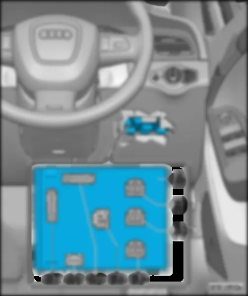
AUDI Q5 2011 6-pin coupling station of A-pillar driver side6-pin coupling station of A-pillar driver side |
| Fitting location, 6-pin coupling station of A-pillar driver side for models with left-hand drive: | | On A-pillar in driver footwell, behind side trim. | Note: | t | Figure shows left-hand drive model. | | t | Figure for models with right-hand drive | | | | | F - | Front passenger seat adjustment thermal fuse 1 -S46- , 15 A | | G - | Driver seat adjustment thermal fuse 1 -S44- , 15 A |
| F - | Front passenger seat adjustment thermal fuse 1 -S46- , 15 A | | G - | Driver seat adjustment thermal fuse 1 -S44- , 15 A |
AUDI Q5 2011 6-pin coupling station of A-pillar passenger side6-pin coupling station of A-pillar passenger side |
| for models with left-hand drive only, with right-hand drive | Note: | t | Figure shows left-hand drive model. | | t | Figure for models with right-hand drive | | | | | G1 - | Terminal 30 fuse, trailer towing attachment -S77- , 30 A |
| for models with right-hand drive only, for models with left-hand drive | Note: | t | Figureshowsright-hand drivemodel. | | t | Figure for models with left-hand drive | | | | | F - | ABS control unit fuse 1 -S123- , 40 A | | G1 - | ABS control unit fuse 3 -S137- , 25 A | | G2 - | ABS control unit fuse 2 -S124- , 5 A |
AUDI Q5 2011 Relay/fuse holder with onboard supply control unit J519Relay/fuse holder with onboard supply control unit -J519- |
| for models with left-hand drive only, for models with right-hand drive | Note: | t | Figure shows left-hand drive model. | | t | Figure for models with right-hand drive | | | | | A - | ABS control unit fuse 1 -S123- , 40 A |
| for models with right-hand drive only; with left-hand drive | Note: | t | Figureshowsright-hand drivemodel. | | t | Figure for models with left-hand drive | | | | | A - | Terminal 30 fuse, trailer towing attachment -S77- , 30 A |
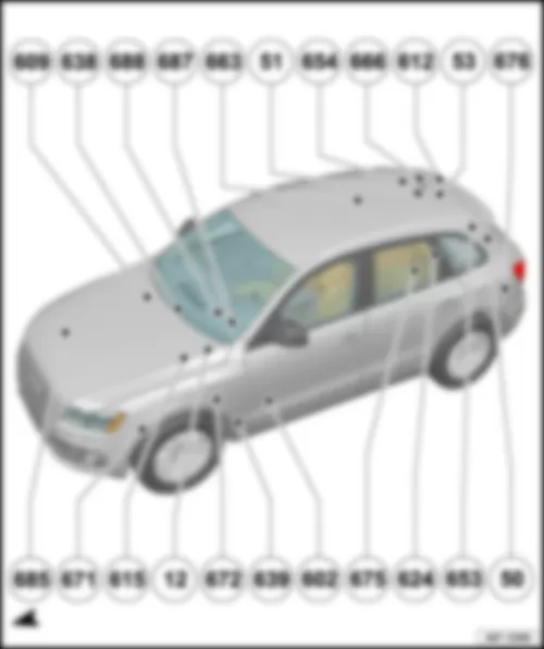
AUDI Q5 2011 Overview of earth points | Overview of earth points | | 609 | Earth point on right in plenum chamber | | 638 | Earth point on right A-pillar | | 688 | Earth point 2 on centre tunnel | | 687 | Earth point 1 on centre tunnel | | | 51 | Earth point on right in luggage compartment | | 654 | Earth point on right D-pillar | | 666 | Earth point on rear right of roof | | 612 | Earth point at centre on rear lid | | 53 | Earth point on right in rear lid |
| 676 | Earth point 2 on left in luggage compartment | | 50 | Earth point on left in luggage compartment | | | 624 | Earth point next to starter battery | | q | Fitting location for models without high-voltage system (hybrid): | | q | Fitting location for models with high-voltage system (hybrid): | | 675 | Earth point 2 on right in luggage compartment | | 602 | Earth point in front left footwell | | 639 | Earth point on left A-pillar | 672 | Earth point 2 on front left longitudinal member | | 12 | Earth point on left in engine compartment |
| 615 | Earth point on left suspension strut | | 671 | Earth point 1 on front left longitudinal member | | 685 | Earth point 1 on front right longitudinal member |
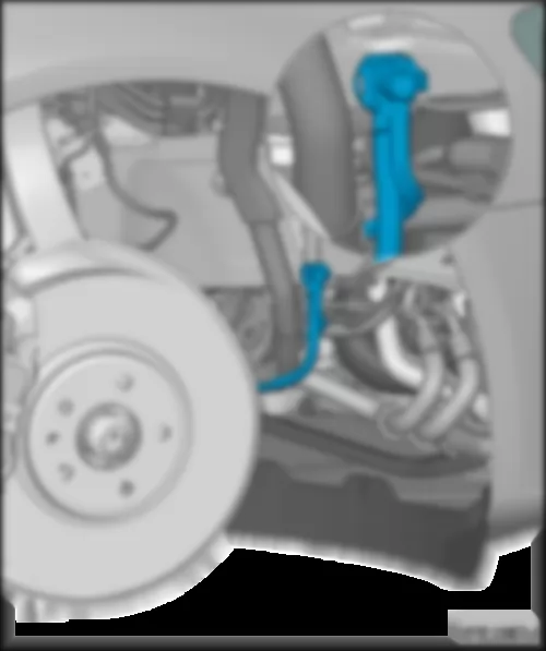
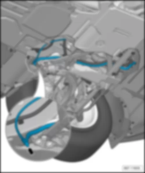
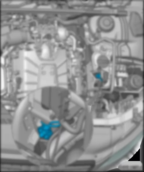
| 685 | Earth point 1 on front right longitudinal member | | on front of right longitudinal member, behind wheel housing | | | | | 672 | Earth point 2 on front left longitudinal member -arrow- | | at bottom on front of left longitudinal member | | | | | 671 | Earth point 1 on front left longitudinal member | | on longitudinal member, near front left wheel housing | | | | | 615 | Earth point on left suspension strut | | on the front left suspension strut chamber | | | | | 12 | Earth point on left in engine compartment | | Between suspension strut chamber and front left plenum chamber | | | | | 609 | Earth point on right in plenum chamber | | | | | 602 | Earth point in front left footwell -arrow- | | Under the carpet in the driver's footwell | | | | | 639 | Earth point on left A-pillar | | behind lower left A-pillar trim | | | | | 638 | Earth point on right A-pillar | | behind lower right A-pillar trim | | | | | 687 | Earth point 1 on centre tunnel | | On the left side of the centre tunnel | | | | | 688 | Earth point 2 on centre tunnel | | On the right side of the centre tunnel | | | | | 663 | Earth point on rear right side panel | | Behind trim/rear right backrest | | | | | 624 | Earth point next to starter battery | | under the floor panel in the luggage compartment, right next to the starter battery | Note | t | Illustration shows model without high-voltage system (hybrid). | | t | Illustration for models with high-voltage system (hybrid) . | | | | | 624 | Earth point next to starter battery | | under the floor panel in the luggage compartment, right next to the starter battery | Note | t | Illustration shows model with high-voltage system (hybrid). | | t | Illustration for models without high-voltage system (hybrid) . | | | | | 675 | Earth point 2 on right in luggage compartment -arrow- | | under the floor panel in the luggage compartment, right next to the starter battery | | | | | 666 | Earth point on rear right of roof | | Behind the trim of rear roof cross member | | | | | 676 | Earth point 2 on left in luggage compartment -arrow- | | On left in luggage compartment, under trim | | | | | 653 | Earth point on left D-pillar | | behind left D-pillar trim | | | | | 50 | Earth point on left in luggage compartment | | behind left D-pillar trim | | | | | 654 | Earth point on right D-pillar | | behind right D-pillar trim | | | | | 51 | Earth point on right in luggage compartment | | behind right D-pillar trim | | | | | 53 | Earth point on right in rear lid | | On right rear window frame, behind trim | | | | | 612 | Earth point at centre on rear lid | | On upper rear lid, near 3rd brake light | | | |
AUDI Q5 2011 Overview of coupling stations | Overview of coupling stations | | q | Fitting location for models with right-hand drive: | | q | Fitting location for models with right-hand drive: | | q | Fitting location for models with -R199- as Audi music interface (AMI - CAN): | | q | Fitting location for models with -R199- as AUX connection: |
| q | Fitting location for models with right-hand drive: | | q | Fitting location for models with right-hand drive: | | q | Pin and screw connection: -T17q-, -T17r-, -T17t-, 501 | | q | Fitting location for models with left-hand drive: | | q | Fitting location for models with right-hand drive: |
AUDI Q5 2011 6-pin coupling station of A-pillar front passenger side6-pin coupling station of A-pillar front passenger side |
| applicable up to model year 2009 | | 2) | applicable from model year 2010 | Note | t | Illustration shows model with left-hand drive. | | t | Illustration for models with right-hand drive . | | | | | 1 - | 10-pin connector, black -T10y- | | 2 - | 10-pin connector, red -T10ab- | | 2 - | 17-pin connector, yellow -T17x- | | 3 - | 17-pin connector, blue -T17a- | | 4 - | 17-pin connector, black -T17g- | | 5 - | 17-pin connector, brown -T17f- | | 6 - | 10-pin connector, grey -T10ac- | | 6 - | 17-pin connector, white -T17w- | | D - | 5-pin connector, yellow -T5c- |
| applicable up to model year 2009 | | | | | 2 - | 10-pin connector, red -T10ab- | | 2 - | 17-pin connector, yellow -T17x- | | 4 - | 17-pin connector, brown -T17d- | | 5 - | 17-pin connector, black -T17c- | | 6 - | 10-pin connector, grey -T10ac- | | D - | 5-pin connector, yellow -T5c- |
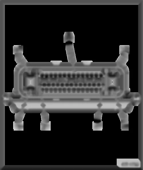
AUDI Q5 2011 Fuse holder D SDFuse holder D -SD- |
| Fitting location for fuse holder D -SD- for models with left-hand drive: | | Below the dash panel cover, front passenger side | Note | t | Illustration shows model with left-hand drive. | | t | Illustration for models with right-hand drive . | | | | | A - | 46-pin connector, black, CAN disconnector, dash panel -T46s- |
| A - | 46-pin connector, black, CAN disconnector, dash panel -T46s- |
AUDI Q5 2011 Seat wiring coupling station, driver sideSeat wiring coupling station, driver side |
| under driver seat in vehicle floor | | 1 - | 6-pin connector, green -T6l- | | 2 - | 10-pin connector, red -T10p- | | 3 - | 10-pin connector, black -T10o- | | 4 - | 2-pin connector, blue-purple -T2da- | | 5 - | 3-pin connector, yellow -T3k- | | | |
AUDI Q5 2011 Seat wiring coupling station, front passenger sideSeat wiring coupling station, front passenger side |
| under front passenger seat in vehicle floor | | 1 - | 6-pin connector, green -T6k- | | 2 - | 10-pin connector, red -T10m- | | 3 - | 10-pin connector, black -T10n- | | 4 - | 2-pin connector, blue-purple -T2db- | | 5 - | 3-pin connector, yellow -T3h- |
AUDI Q5 2011 6-pin coupling station of A-pillar driver side6-pin coupling station of A-pillar driver side |
| applicable up to model year 2009 | Note | t | Illustration shows model with left-hand drive. | | t | Illustration for models with right-hand drive . | | | | | 1 - | 17-pin connector, green -T17j- | | 2 - | 17-pin connector, red -T17e- | | 4 - | 17-pin connector, brown -T17d- | | 5 - | 17-pin connector, black -T17c- | | 6 - | 17-pin connector, blue -T17b- | | A - | 5-pin connector, yellow -T5b- | | E - | 46-pin connector, black, CAN disconnector -T46i- |
| applicable up to model year 2009 | Note | t | Illustration shows model with right-hand drive. | | t | Illustration for models with left-hand drive . | | | | | 2 - | 17-pin connector, red -T17e- | | 3 - | 17-pin connector, green -T17j- | | 4 - | 17-pin connector, blue -T17b- | | 5 - | 17-pin connector, brown -T17f- | | 6 - | 17-pin connector, black -T17g- | | A - | 5-pin connector, yellow -T5b- | | E - | 46-pin connector, black, CAN disconnector -T46i- |
AUDI Q5 2011 Relay/ fuse holder B SBRelay/fuse holder B -SB- |
| Fitting location for relay/fuse holder B -SB- for models with left-hand drive: | | In electronics box in plenum chamber, driver side | Note | t | Illustration shows model with left-hand drive. | | t | Illustration for models with right-hand drive . | | | | | G - | 17-pin connector, red -T17q- | | H - | 17-pin connector, white -T17r- | | I - | 17-pin connector, brown -T17t- | | M - | 501Screw connection 2 (30), on relay plate |
| G - | 17-pin connector, red -T17q- | | H - | 17-pin connector, white -T17r- | | I - | 17-pin connector, brown -T17t- | | M - | 501Screw connection 2 (30), on relay plate |
AUDI Q5 2011 Relay/fuse holder with onboard supply control unit J519Relay/fuse holder with onboard supply control unit -J519- |
| Fitting location for relay/fuse holder with onboard supply control unit -J519- for models with left-hand drive: | | Below the dash panel, driver side | Note | t | Illustration shows model with left-hand drive. | | t | Illustration for models with right-hand drive . | | | | | 6 - | 500Screw connection 1 (30), on relay plate |
| 5 - | 500Screw connection 1 (30), on relay plate |
AUDI Q5 2011 Connection for external audio sources R199 as Audi music interface (AMI - MOST)Connection for external audio sources -R199- as Audi music interface (AMI - MOST) |
Note | For models with Audi music interface only (AMI - MOST) only. | | | | | A - | Connection for external audio sources -R199- |
AUDI Q5 2011 Connection for external audio sources R199 as Audi music interface (AMI - CAN)Connection for external audio sources -R199- as Audi music interface (AMI - CAN) |
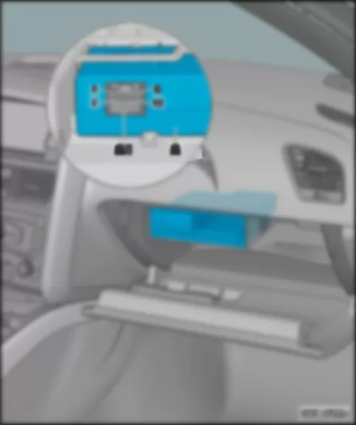
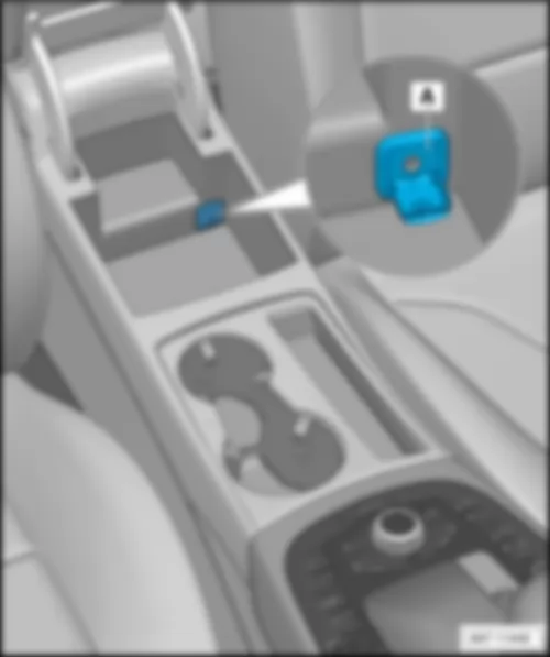
Note | For models with Audi music interface only (AMI - CAN) only. | | | | | A - | Connection for external audio sources -R199- | AUDI Q5 2011 Connection for external audio sources R199 as AUX connection | Connection for external audio sources -R199- as AUX connection | Note | For models with AUX connection only. | | | | | A - | Connection for external audio sources -R199- |
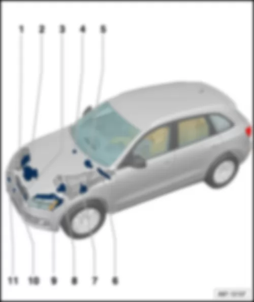
AUDI Q5 2011 Overview of control units | Overview of control units |

