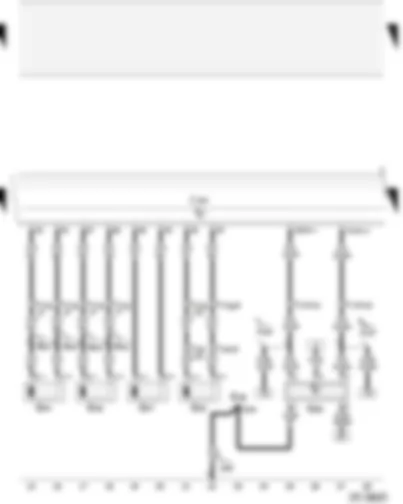
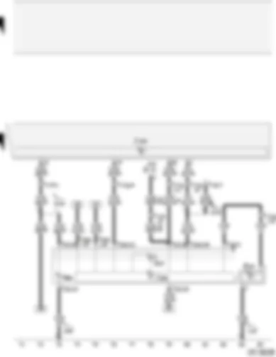
| A | Battery |
| B | Starter |
| D | Ignition/starter switch |
| J104 | ABS with EDL control unit |
| S88 | Strip fuse |
| S123 | ABS control unit fuse 1 |
| SB30 | Fuse -30- on fuse box |
| SB40 | Fuse -40- on fuse box |
| 65 | Earth point, left longitudinal member, rear, between B and C pillar |
| 500 | Screw connection -1- (30), on relay plate |
| 639 | Earth point, left A pillar |
| A2 | Positive (+) connection (15), in dash panel wiring harness |
| A32 | Positive (+) connection (30), in dash panel wiring harness |
| A98 | Positive (+) connection -4- (30), in dash panel wiring harness |
| B156 | Positive (+) connection (30a), in interior wiring harness |
| D68 | Positive (+) connection (30 - for ABS), in engine compartment wiring harness |
| P2 | Positive (+) connection (30), in battery wiring harness |
| * | Only applies to models with engine codes ANY, AMF, ATL and BHC |
| ** | Only applies to models with engine codes BAD and BBY |
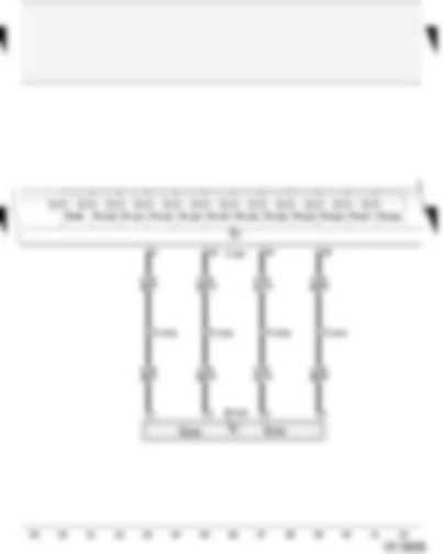
| E38 | Intermittent wiper control |
| G44 | Rear right speed sensor |
| G45 | Front right speed sensor |
| G46 | Rear left speed sensor |
| G47 | Front left speed sensor |
| G85 | Steering angle sender |
| J104 | ABS with EDL control unit |
| T6 | 6-pin connector, brown, behind steering column switch trim |
| T10i | 10-pin connector, black, connector point, A pillar, right |
| T17f | 17-pin connector, white, connector point, A pillar, left |
| T17g | 17-pin connector, red, connector point, A pillar, left |
| 249 | Earth connection -2-, in interior wiring harness |
| A121 | Connection (high bus), in dash panel wiring harness |
| A122 | Connection (low bus), in dash panel wiring harness |
| B510 | Connection -1- (rear right speed sensor), in interior wiring harness |
| B511 | Connection -2- (rear right speed sensor), in interior wiring harness |
| B512 | Connection -1- (rear left speed sensor), in interior wiring harness |
| B513 | Connection -2- (rear left speed sensor), in interior wiring harness |
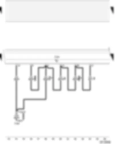
| G200 | Lateral acceleration sender |
| G202 | Yaw rate sender |
| G419 | ESP sensor unit |
| J104 | ABS with EDL control unit |
| N99 | ABS inlet valve, front right |
| N100 | ABS outlet valve, front right |
| N101 | ABS inlet valve, front left |
| N102 | ABS outlet valve, front left |
| N133 | ABS inlet valve, rear right |
| N134 | ABS inlet valve, rear left |
| N135 | ABS outlet valve, rear right |
| N136 | ABS outlet valve, rear left |
| N225 | Electronic stabilisation program switch valve -1- |
| N226 | Electronic stabilisation program switch valve -2- |
| N227 | Electronic stabilisation program high pressure valve -1- |
| N228 | Electronic stabilisation program high pressure valve -2- |
| T17f | 17-pin connector, white, connector point, A pillar, left |
| J104 | ABS with EDL control unit |
| J402 | Operating electronics control unit, navigation |
| T17g | 17-pin connector, red, connector point, A pillar, left |
| T26 | 26-pin connector, black, radio connector |
| * | Only applies to models with engine code ANY, without power steering |
| ** | Only applies to models with engine code ANY, with power steering |
| *** | Only applies to models with engine codes AMF, BBY and BHC |
| **** | Only applies to models with engine codes ATL and BAD |
| ***** | Only applies to models with radio navigation system |
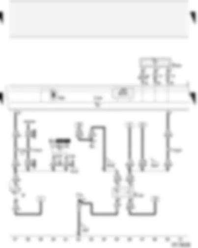
| E1 | Lighting switch |
| E132 | Traction control system switch |
| F | Brake light switch |
| G201 | Brake pressure sender -1- |
| J31 | Automatic intermittent wash/wipe relay |
| J104 | ABS with EDL control unit |
| K41 | Bulb check warning unit |
| T17e | 17-pin connector, blue, in footwell, front left |
| T17g | 17-pin connector, red, connector point, A pillar, left |
| V64 | ABS hydraulic pump |
| 249 | Earth connection -2-, in interior wiring harness |
| B131 | Connection (54), in interior wiring harness |
| B145 | Positive (+) connection (58b), in interior wiring harness |
| B157 | Positive (+) connection -3- (15a), in interior wiring harness |
| * | With the introduction of MK60, generation 2, no longer fitted, phased-in modification |
| ** | Phased-in modification, with the introduction of MK60, generation 2 |
| *** | Only applies to models with driver information system |
| **** | ⇒ Applicable engine Current Flow Diagram |
| G22 | Speedometer sender (Hall sender, on gearbox) |
| G34 | Brake lining/pad wear sender, front left |
| J104 | ABS with EDL control unit |
| J285 | Control unit with display in dash panel insert |
| K47 | ABS warning lamp |
| K86 | Traction control system warning lamp |
| T16 | 16-pin connector, diagnostic connector, black, near fuse box |
| T17e | 17-pin connector, blue, in footwell, front left |
| T17f | 17-pin connector, white, connector point, A pillar, left |
| T17g | 17-pin connector, red, connector point, A pillar, left |
| T32 | 32-pin connector, blue, on dash panel insert |
| T32a | 32-pin connector, green, on dash panel insert |
| 119 | Earth connection -1-, in headlight wiring harness |
| 249 | Earth connection -2-, in interior wiring harness |
| A76 | Connection (diagnosis wire K), in dash panel wiring harness |
| A132 | Connection (TCS/ESP), in dash panel wiring harness |
| * | Does not apply to models with engine code ANY |
| ** | Only applies to models with engine code ANY |

