| Audi A5 Cabriolet |
Current Flow Diagram |
No.
11 /
1
|
|
Wiring diagrams AUDI
7-speed dual clutch gearbox 0B5 (S tronic)
From January 2009
| Audi A5 Cabriolet |
Current Flow Diagram |
No.
11 /
2 |
|
| Audi A5 Cabriolet |
Current Flow Diagram |
No.
11 /
3 |
|
|
|
ws |
= |
white |
|
sw |
= |
black |
|
ro |
= |
red |
|
rt |
= |
red |
|
br |
= |
brown |
|
gn |
= |
green |
|
bl |
= |
blue |
|
gr |
= |
grey |
|
li |
= |
purple |
|
vi |
= |
purple |
|
ge |
= |
yellow |
|
or |
= |
orange |
|
rs |
= |
pink |
| |
| |
| |
| |
| |
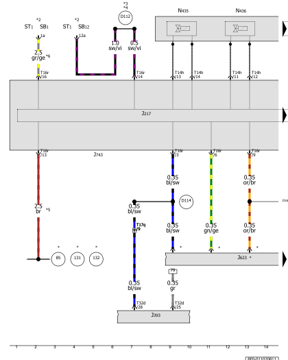
| Automatic gearbox control unit, Data bus diagnostic interface, Valve 3 in sub-gearbox 2, Valve 4 in sub-gearbox 2, Cooling oil valve, Main pressure valve
| J217 |
-
|
Automatic gearbox control unit |
| J533 |
-
|
Data bus diagnostic interface |
| J623 |
-
|
Engine control unit |
| J743 |
-
|
Mechatronic unit for dual clutch gearbox |
| N439 |
-
|
Valve 3 in sub-gearbox 2 |
| N440 |
-
|
Valve 4 in sub-gearbox 2 |
| N472 |
-
|
Main pressure valve |
| T14h |
-
|
14-pin connector |
| T16r |
-
|
16-pin connector |
| T17b |
-
|
17-pin connector, blue |
| T17r |
-
|
17-pin connector, white |
| T20d |
-
|
20-pin connector |
| B383 |
-
|
Connection 1 (powertrain CAN bus, high), in main wiring harness |
| B385 |
-
|
Connection 3 (powertrain CAN bus, high), in main wiring harness |
| B390 |
-
|
Connection 1 (powertrain CAN bus, low), in main wiring harness |
| B392 |
-
|
Connection 3 (powertrain CAN bus, low), in main wiring harness |
| D159 |
-
|
Connection (high bus), in engine compartment wiring harness |
| D160 |
-
|
Connection (low bus), in engine compartment wiring harness |
| * |
-
|
see applicable current flow diagram for engine |
|
| Audi A5 Cabriolet |
Current Flow Diagram |
No.
11 /
4 |
|
|
|
ws |
= |
white |
|
sw |
= |
black |
|
ro |
= |
red |
|
rt |
= |
red |
|
br |
= |
brown |
|
gn |
= |
green |
|
bl |
= |
blue |
|
gr |
= |
grey |
|
li |
= |
purple |
|
vi |
= |
purple |
|
ge |
= |
yellow |
|
or |
= |
orange |
|
rs |
= |
pink |
| |
| |
| |
| |
| |
| Automatic gearbox hydraulic pressure sender 1, Gear selector movement sensor 1, Gear selector movement sensor 2, Gear selector movement sensor 3, Gear selector movement sensor 4, Automatic gearbox control unit
| G193 |
-
|
Automatic gearbox hydraulic pressure sender 1 |
| G487 |
-
|
Gear selector movement sensor 1 |
| G488 |
-
|
Gear selector movement sensor 2 |
| G489 |
-
|
Gear selector movement sensor 3 |
| G490 |
-
|
Gear selector movement sensor 4 |
| J217 |
-
|
Automatic gearbox control unit |
| J743 |
-
|
Mechatronic unit for dual clutch gearbox |
| N433 |
-
|
Valve 1 in sub-gearbox 1 |
| N434 |
-
|
Valve 2 in sub-gearbox 1 |
| N437 |
-
|
Valve 1 in sub-gearbox 2 |
| N438 |
-
|
Valve 2 in sub-gearbox 2 |
| T14i |
-
|
14-pin connector |
|
| Audi A5 Cabriolet |
Current Flow Diagram |
No.
11 /
5 |
|
| Audi A5 Cabriolet |
Current Flow Diagram |
No.
11 /
6 |
|
| Audi A5 Cabriolet |
Current Flow Diagram |
No.
11 /
7 |
|
Can't find your car? Check -> DiagnostData.com!
 English