| Audi A7 |
Current Flow Diagram |
No.
13 /
1
|
|
Wiring diagrams AUDI
7-speed dual clutch gearbox 0B5 (S tronic)
From September 2010
| Audi A7 |
Current Flow Diagram |
No.
13 /
2 |
|
| Audi A7 |
Current Flow Diagram |
No.
13 /
3 |
|
| Audi A7 |
Current Flow Diagram |
No.
13 /
4 |
|
|
|
ws |
= |
white |
|
sw |
= |
black |
|
ro |
= |
red |
|
rt |
= |
red |
|
br |
= |
brown |
|
gn |
= |
green |
|
bl |
= |
blue |
|
gr |
= |
grey |
|
li |
= |
purple |
|
vi |
= |
purple |
|
ge |
= |
yellow |
|
or |
= |
orange |
|
rs |
= |
pink |
| |
| |
| |
| |
| |
| Automatic gearbox control unit
| G487 |
-
|
Gear selector movement sensor 1 |
| G488 |
-
|
Gear selector movement sensor 2 |
| G489 |
-
|
Gear selector movement sensor 3 |
| G490 |
-
|
Gear selector movement sensor 4 |
| J217 |
-
|
Automatic gearbox control unit |
| J743 |
-
|
Mechatronic unit for dual clutch gearbox |
| N433 |
-
|
Valve 1 in sub-gearbox 1 |
| N434 |
-
|
Valve 2 in sub-gearbox 1 |
| N437 |
-
|
Valve 1 in sub-gearbox 2 |
| N438 |
-
|
Valve 2 in sub-gearbox 2 |
|
| Audi A7 |
Current Flow Diagram |
No.
13 /
5 |
|
|
|
ws |
= |
white |
|
sw |
= |
black |
|
ro |
= |
red |
|
rt |
= |
red |
|
br |
= |
brown |
|
gn |
= |
green |
|
bl |
= |
blue |
|
gr |
= |
grey |
|
li |
= |
purple |
|
vi |
= |
purple |
|
ge |
= |
yellow |
|
or |
= |
orange |
|
rs |
= |
pink |
| |
| |
| |
| |
| |
| Automatic gearbox control unit
| G193 |
-
|
Automatic gearbox hydraulic pressure sender 1 |
| G194 |
-
|
Automatic gearbox hydraulic pressure sender 2 |
| G509 |
-
|
Clutch temperature sender |
| G510 |
-
|
Temperature sender in control unit |
| G612 |
-
|
Gearbox input speed sender 2 |
| G632 |
-
|
Gearbox input speed sender 1 |
| G641 |
-
|
Gearbox input speed sender 3 |
| J217 |
-
|
Automatic gearbox control unit |
| J743 |
-
|
Mechatronic unit for dual clutch gearbox |
|
| Audi A7 |
Current Flow Diagram |
No.
13 /
6 |
|
|
|
ws |
= |
white |
|
sw |
= |
black |
|
ro |
= |
red |
|
rt |
= |
red |
|
br |
= |
brown |
|
gn |
= |
green |
|
bl |
= |
blue |
|
gr |
= |
grey |
|
li |
= |
purple |
|
vi |
= |
purple |
|
ge |
= |
yellow |
|
or |
= |
orange |
|
rs |
= |
pink |
| |
| |
| |
| |
| |
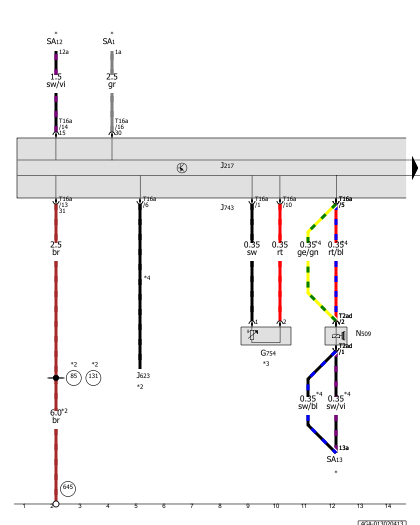
| Gear selector position P switch, Automatic gearbox control unit, Onboard supply control unit, Selector lever sensors control unit
| E408 |
-
|
Entry and start authorisation button |
| F305 |
-
|
Gear selector position P switch |
| J217 |
-
|
Automatic gearbox control unit |
| J519 |
-
|
Onboard supply control unit |
| J587 |
-
|
Selector lever sensors control unit |
| J743 |
-
|
Mechatronic unit for dual clutch gearbox |
| N110 |
-
|
Selector lever lock solenoid |
| SF4 |
-
|
Fuse 4 in fuse holder F |
| T16a |
-
|
16-pin connector, black |
| T17b |
-
|
17-pin connector, Coupling station, E-box on left in plenum chamber, red |
| T32a |
-
|
32-pin connector |
| 373 |
-
|
Earth connection 8, in main wiring harness |
| 687 |
-
|
Earth point 1, on centre tunnel |
| B286 |
-
|
Positive connection 10 (15a) in main wiring harness |
| B733 |
-
|
Connection 3 (58s), in main wiring harness |
| * |
-
|
see applicable current flow diagram for fuse assignment |
|
| Audi A7 |
Current Flow Diagram |
No.
13 /
7 |
|
|
|
ws |
= |
white |
|
sw |
= |
black |
|
ro |
= |
red |
|
rt |
= |
red |
|
br |
= |
brown |
|
gn |
= |
green |
|
bl |
= |
blue |
|
gr |
= |
grey |
|
li |
= |
purple |
|
vi |
= |
purple |
|
ge |
= |
yellow |
|
or |
= |
orange |
|
rs |
= |
pink |
| |
| |
| |
| |
| |
| Automatic gearbox control unit, Wiring junction for powertrain CAN bus, high
| J217 |
-
|
Automatic gearbox control unit |
| J533 |
-
|
Data bus diagnostic interface |
| J623 |
-
|
Engine control unit |
| J743 |
-
|
Mechatronic unit for dual clutch gearbox |
| T16a |
-
|
16-pin connector, black |
| T17a |
-
|
17-pin connector, Coupling station, E-box on left in plenum chamber, white |
| T32b |
-
|
32-pin connector |
| T46a |
-
|
46-pin connector |
| T46b |
-
|
46-pin connector, black |
| TV33 |
-
|
Wiring junction for powertrain CAN bus, high |
| TV37 |
-
|
Wiring junction for powertrain CAN bus, low |
| B383 |
-
|
Connection 1 (powertrain CAN bus, high), in main wiring harness |
| B390 |
-
|
Connection 1 (powertrain CAN bus, low), in main wiring harness |
| E93 |
-
|
Connection 1 (CAN bus high), in engine wiring harness |
| E94 |
-
|
Connection 1 (CAN bus low), in engine wiring harness |
| * |
-
|
see applicable current flow diagram for engine |
| *2 |
-
|
Data bus wire (CAN bus) |
|
Can't find your car? Check -> DiagnostData.com!
 English