Wiring diagram - RADIO - Alfa Romeo GT 2.0 JTS
Component location - RADIO - Alfa Romeo GT 2.0 JTS
Components - RADIO - Alfa Romeo GT 2.0 JTS
| Component code | Description | Reference to the assembly |
| B1 | JUNCTION UNIT | - |
| B1 | JUNCTION UNIT | |
| B2 | JUNCTION UNIT UNDER DASHBOARD | |
| B5 | MAXI FUSE-1 BOX | - |
| B98 | SUPPLEMENTARY FUSE BOX ( REAR ) | - |
| B99 | MAXIFUSE BOX ON BATTERY | |
| C15 | FACIA EARTH, DRIVER''S SIDE | - |
| C65 | HI-FI SYSTEM EARTH | - |
| D20 | REAR DASHBOARD COUPLING ( REAR ) | - |
| D30 | REAR COUPLING FOR /FRONT DOOR. DRIVER''S SIDE | - |
| D31 | RIGHT FRONT DOOR REAR COUPLING/. | - |
| D41 | REAR DASHBOARD COUPLING FOR SPEAKERS ( FACIA ) | - |
| D47 | CLOCK SPRING ON STEERING WHEEL | |
| D68 | HI SYSTEM JUNCTION | - |
| D68 | Centre console/rear coupling | - |
| D68 | Centre console / rear coupling | - |
| D97 | SHORT CIRCUITING COUPLING | - |
| H1 | IGNITION SWITCH | |
| M1 | BODY COMPUTER | |
| P2 | INTERIOR MICROPHONE CAPSULE | - |
| P20 | RADIO | |
| P20 | RADIO | |
| P25 | AERIAL AMPLIFIER FEEDER ( REAR ) | |
| P30 | LEFT REAR SPEAKER ( REAR ) | |
| P31 | RIGHT REAR SPEAKER ( REAR ) | |
| P35 | SPEAKER IN DRIVER''S FRONT DOOR | |
| P36 | SPEAKER IN FRONT PASSENGER DOOR ( FRONT PASSENGER DOOR ) | |
| P45 | DRIVER''S FRONT TWEETER SPEAKER | |
| P46 | FRONT PASSENGER SIDE TWEETER SPEAKER ( FRONT PASSENGER DOOR ) | |
| P47 | REAR LEFT TWEETER SPEAKER | |
| P48 | REAR RIGHT TWEETER SPEAKER | |
| P49 | REAR SUBWOOFER SPEAKER ( CONNECTORS ) | 5580T |
| P70 | BOSE RADIO AMPLIFIER ( CONNECTORS ) | 5580T |
| P75 | CD MULTI-PLAYER ( CD MULTI ) | |
Description - RADIO - Alfa Romeo GT 2.0 JTS
The vehicle has a radio system comprising:radio (different versions are available: baseor CONNECT)front speakers (separate woofers and tweeters) located in the front doors;rear speakers (separate woofers and tweeters) located in the rear doors;radio supply cablesleads connecting the radio to the speakers;fishpole antenna with base mounted on the rear of the roof, coaxial cable and supply cable for aerial amplifier.
A radio with a cassette player (CC) is fitted on the "basic" version .A radio with a compact disc player (CD) can also be installed.If a built-in radio-telephone-navigator is fitted, the radio is incorporated in the unit.The radio is designed to operate the 10 -disc multiple CD-CHANGER located in the luggage compartment, on the right hand side.767if preparation for a cell phone is fittedor a radio telephone, then the aerial is the dual function type (radio/GSM); if a navigator is also installedthen the aerial has three functions (radio/GSM/GPS).It is also possible to fit a multi-polar cable connecting the radio to a CD player located in the boot, on the left hand side.
Description - RADIO - Alfa Romeo GT 2.0 JTS
A sophisticated Bose HIFI system with special HIFI speakers and an outside amplifier can also be fitted.
Description - RADIO - Alfa Romeo GT 2.0 JTS
The radio is a CAN node through which information is exchanged with the Body Computer and with the other electronic units.The radio receives the vehicle on signal via the CAN and is operated according to the following logic:if the radio is on and the vehicle is off, the radio switches off;if the vehicle is switched on and the radio was on previously, the radio remains on;if the vehicle is switched on and the radio was off previously, the radio remains off;if the radio is left on with the ignition OFF, it switches off automatically after 20 minutes;
The radio is equipped with an anti-theft system through the connection of the radio at the CAN with the Body ComputerWhen a new radio is fitted on the vehicle a connection is made with the Body Computer which requests the radio code: this code, supplied by the manufacturer, is entered using the numerical keys, the Body Computer memorizes this code and verifies it each time the radio is turned on.For more detailsor)- The radio also controls the volume linked to the vehicle speed: the volume increases and decreases in relation to the speed of the vehicle: this information reaches the radio node via the CAN.Some versions are equipped with a series of buttons on the steering wheel: these make it possible to replicate some of the commands which are acquired in the same way by the actual radio.The radio controls shown on the radio display are also duplicated on the instrument panel.
Operational description - RADIO - Alfa Romeo GT 2.0 JTS
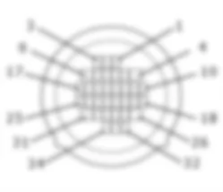
The radio P20receives a direct power supply (7 of connector A) from the battery via the line for fuse F39 of the junction unit under the dashboard B2and maxifuse CPL of B99.The power supply reaches pin 4 of connector A with the side lights on.The CAN line arrives at pins 1 and 3 of connector A with which the radio P20is connected to the Body Computer M1and to the other system nodes.Pin 8 of connector A is earthed.The aerial P25 receives a power supply from pin 5 of connector A . The aerial is connected to the radio by means of the special coaxial cable.The following cables with signals for the speakers leave connector B:pins 5 and 6 to the left front speakers P35 and P45,pins 3 and 4 to the right front speakers P36 and P46,pins 7 and 8 to the left rear speakers P30 and P47,pins 1 and 2 to the right rear speakers P31 and P48,
Pins 10 and 11 of connector C are connected to the radio controls on the steering wheel: the connection takes place via the clock spring D47; the device which controls the control buttons receives an ignition-operated supply (INT) from the line protected by fuse F51 of the junction unit under the dashboard B2, whilst the reference earth arrives from pin 12 of connector C of P20.The connecting cable leaves connector C of P20 (pins 13-20) for the CD player P75 in accordance with the following connections: - Pin 13 asci bus from CDC to the radio - Pin 14 asci bus from the radio to the CDC - Pin 15 +12 permanent - Pin 16 +12V switched - Pin 17 digital earth - Pin 18 audio earth - Pin 19 left audio CDC - Pin 20 right audio CDCEngine compartment junction unit
B1A
B1A
B1A
B1B
B1B
B1B
B1C
B1C
B1C
B1D
B1E
B1E
B1X
B1X
Junction unit under dashboard
B2A
B2A
B2A
B2A
B2A
B2A
B2B
B2B
B2C
B2C
B2D
B2E
B2F
B2G
B2H
MAXI FUSE box
B5A
B5B
B5C
B5D
B5E
B5F
Supplementary fuse box
B98
Maxifuse box on battery
B99A
B99A
B99B
B99D
Facia earth, driver's side
C15A
C15B
C15C
Bose system earth
C65
Rear dashboard coupling
D20
D20
D20
D20
Rear coupling for front door driver's side
D30
D30
D30
Front passenger door rear coupling
D31
D31
D31
Rear dashboard coupling for speakers
D41
D41
Clock spring coupling
D47
D47
Bose system coupling
D68A
D68A
D68B
D68B
D68C
D68C
D68D
D68D
Short circuiting coupling
D97A
D97A
D97A
D97C
D97D
D97E
D97G
D97H
D97I
D97M
Ignition switch
H1A
H1A
H1B
Body computer
M1A
M1A
M1A
M1A
M1A
M1A
M1B
M1C
M1D
M1E
M1F
M1G
Interior microphone capsule
P2
Radio
P20A
P20A
P20B
P20B
P20B
P20B
P20C
P20C
P20C
P20C
P20D
P20C
Aerial amplifier feeder
P25
Left rear speaker
P30
P30
Right rear speaker
P31
P31
Speaker in driver's front door
P35
Speaker in front passenger door
P36
Driver's front tweeter speaker
P45
Front passenger side tweeter speaker
P46
Rear left tweeter speaker
P47
Rear right tweeter speaker
P48
Rear subwoofer speaker
P49
Bose radio amplifier
P70
CD multi-player
P75


