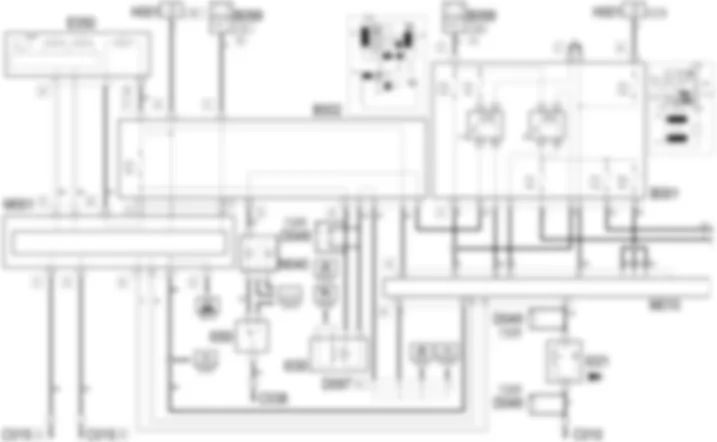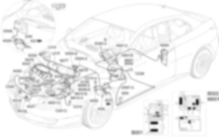
Wiring diagram - PETROL ENGINE ELECTRONIC MANAGEMENT - Alfa Romeo GT 2.0 JTS
Components - PETROL ENGINE ELECTRONIC MANAGEMENT - Alfa Romeo GT 2.0 JTS
| Component code | Description | Reference to the assembly |
| A30 | IGNITION ''COIL | |
| A30 | IGNITION ''COIL | |
| B1 | JUNCTION UNIT | - |
| B1 | JUNCTION UNIT | |
| B1 | JUNCTION UNIT | |
| B002 | Junction unit under dashboard | |
| B5 | MAXI FUSE-1 BOX | - |
| B99 | MAXIFUSE BOX ON BATTERY | |
| C1 | BATTERY EARTH | - |
| C10 | FRONT LEFT EARTH ( FRONT ) | - |
| C15 | FACIA EARTH, DRIVER''S SIDE | - |
| C38 | EARTH ON TUNNEL | - |
| C40 | ENGINE EARTH | - |
| D4 | Front/engine coupling | - |
| D7 | Front/recharging coupling | - |
| D49 | PEDAL ASSEMBLY JOIN | - |
| D97 | SHORT CIRCUITING COUPLING | - |
| E50 | INSTRUMENT PANEL | |
| H1 | IGNITION SWITCH | |
| I30 | BRAKE PEDAL SWITCH ( FRONT ) | |
| I31 | CLUTCH PEDAL SWITCH ( FRONT ) | 1056B |
| I50 | INERTIAL SWITCH | |
| K105 | BRAKE SERVO VACUUM UNIT SENSOR | - |
| K105 | BRAKE SERVO VACUUM UNIT SENSOR | |
| K15 | LAMBDA SENSOR ON PRE-CATALYZER | |
| K16 | LAMBDA SENSOR ON PRE-CATALYZER -2 ( CONNECTORS ) | |
| K17 | LAMBDA SENSOR ON CATALYZER ( CONNECTORS ) | |
| K18 | LAMBDA SENSOR ON CATALYZER 2 ( CONNECTORS ) | |
| K30 | ENGINE OIL PRESSURE SENSOR SWITCH ( CONNECTORS ) | |
| K36 | ENGINE TEMPERATURE SENDER UNIT ( CONNECTORS ) | 1056B |
| K36 | ENGINE TEMPERATURE SENDER UNIT ( CONNECTORS ) | Op. 1056F ALIMENTAZIONE INIEZIONE DIRETTA BENZINA |
| K41 | AIR FLOW METER ( FRONT ) | 1056B |
| K46 | RPM SENSOR ( CONNECTORS ) | |
| K47 | TIMING SENSOR. ( CONNECTORS ) | 1056B |
| K47 | TIMING SENSOR. ( CONNECTORS ) | Op. 1056F ALIMENTAZIONE INIEZIONE DIRETTA BENZINA |
| K50 | DETONATION SENSOR 1 ( CONNECTORS ) | |
| K50 | DETONATION SENSOR 1 ( CONNECTORS ) | |
| K51 | KNOCK SENSOR -2 | |
| K55 | ACCELERATOR PEDAL POTENTIOMETER ( FRONT ) | |
| K83 | FUEL PRESSURE SENSOR | Op. 1056F ALIMENTAZIONE INIEZIONE DIRETTA BENZINA |
| L10 | FUEL VAPOUR RECOVERY SOLENOID | |
| L10 | FUEL VAPOUR RECOVERY SOLENOID | |
| L15 | VARIABLE GEOMETRY CONTROL SOLENOID ( CONNECTORS ) | |
| L20 | AIR CONDITIONING COMPRESSOR ENGAGEMENT ELECTRO-MAGNET ( CONNECTORS ) | |
| M1 | BODY COMPUTER | |
| M10 | ENGINE MANAGEMENT ECU | 1056B |
| N40 | FUEL PUMP AND SENDER UNIT | |
| N70 | INJECTOR | 1056B |
| N75 | THROTTLE BODY ACTUATOR ( CONNECTORS ) | 1056B |
| N76 | TIMING VARIATOR ACTUATOR | Op. 1056F ALIMENTAZIONE INIEZIONE DIRETTA BENZINA |
| N77 | FUEL PRESSURE REGULATOR ( CONNECTORS ) | Op. 1056F ALIMENTAZIONE INIEZIONE DIRETTA BENZINA |
Component location - PETROL ENGINE ELECTRONIC MANAGEMENT - Alfa Romeo GT 2.0 JTS
Components - PETROL ENGINE ELECTRONIC MANAGEMENT - Alfa Romeo GT 2.0 JTS
| Component code | Description | Reference to the assembly |
| A30 | IGNITION ''COIL | |
| A30 | IGNITION ''COIL | |
| B1 | JUNCTION UNIT | - |
| B1 | JUNCTION UNIT | |
| B1 | JUNCTION UNIT | |
| B002 | Junction unit under dashboard | |
| B5 | MAXI FUSE-1 BOX | - |
| B99 | MAXIFUSE BOX ON BATTERY | |
| C1 | BATTERY EARTH | - |
| C10 | FRONT LEFT EARTH ( FRONT ) | - |
| C15 | FACIA EARTH, DRIVER''S SIDE | - |
| C38 | EARTH ON TUNNEL | - |
| C40 | ENGINE EARTH | - |
| D4 | Front/engine coupling | - |
| D7 | Front/recharging coupling | - |
| D49 | PEDAL ASSEMBLY JOIN | - |
| D97 | SHORT CIRCUITING COUPLING | - |
| E50 | INSTRUMENT PANEL | |
| H1 | IGNITION SWITCH | |
| I30 | BRAKE PEDAL SWITCH ( FRONT ) | |
| I31 | CLUTCH PEDAL SWITCH ( FRONT ) | 1056B |
| I50 | INERTIAL SWITCH | |
| K105 | BRAKE SERVO VACUUM UNIT SENSOR | - |
| K105 | BRAKE SERVO VACUUM UNIT SENSOR | |
| K15 | LAMBDA SENSOR ON PRE-CATALYZER | |
| K16 | LAMBDA SENSOR ON PRE-CATALYZER -2 ( CONNECTORS ) | |
| K17 | LAMBDA SENSOR ON CATALYZER ( CONNECTORS ) | |
| K18 | LAMBDA SENSOR ON CATALYZER 2 ( CONNECTORS ) | |
| K30 | ENGINE OIL PRESSURE SENSOR SWITCH ( CONNECTORS ) | |
| K36 | ENGINE TEMPERATURE SENDER UNIT ( CONNECTORS ) | 1056B |
| K36 | ENGINE TEMPERATURE SENDER UNIT ( CONNECTORS ) | Op. 1056F ALIMENTAZIONE INIEZIONE DIRETTA BENZINA |
| K41 | AIR FLOW METER ( FRONT ) | 1056B |
| K46 | RPM SENSOR ( CONNECTORS ) | |
| K47 | TIMING SENSOR. ( CONNECTORS ) | 1056B |
| K47 | TIMING SENSOR. ( CONNECTORS ) | Op. 1056F ALIMENTAZIONE INIEZIONE DIRETTA BENZINA |
| K50 | DETONATION SENSOR 1 ( CONNECTORS ) | |
| K50 | DETONATION SENSOR 1 ( CONNECTORS ) | |
| K51 | KNOCK SENSOR -2 | |
| K55 | ACCELERATOR PEDAL POTENTIOMETER ( FRONT ) | |
| K83 | FUEL PRESSURE SENSOR | Op. 1056F ALIMENTAZIONE INIEZIONE DIRETTA BENZINA |
| L10 | FUEL VAPOUR RECOVERY SOLENOID | |
| L10 | FUEL VAPOUR RECOVERY SOLENOID | |
| L15 | VARIABLE GEOMETRY CONTROL SOLENOID ( CONNECTORS ) | |
| L20 | AIR CONDITIONING COMPRESSOR ENGAGEMENT ELECTRO-MAGNET ( CONNECTORS ) | |
| M1 | BODY COMPUTER | |
| M10 | ENGINE MANAGEMENT ECU | 1056B |
| N40 | FUEL PUMP AND SENDER UNIT | |
| N70 | INJECTOR | 1056B |
| N75 | THROTTLE BODY ACTUATOR ( CONNECTORS ) | 1056B |
| N76 | TIMING VARIATOR ACTUATOR | Op. 1056F ALIMENTAZIONE INIEZIONE DIRETTA BENZINA |
| N77 | FUEL PRESSURE REGULATOR ( CONNECTORS ) | Op. 1056F ALIMENTAZIONE INIEZIONE DIRETTA BENZINA |
Description - PETROL ENGINE ELECTRONIC MANAGEMENT - Alfa Romeo GT 2.0 JTS
The 2.0 JTS engine features a fuel feed system with a high pressure pump for direct injection.An electronic control system supervises and governs all engine parameters to optimise performance and fuel consumption by means of a real-time response to different service conditions.The system is managed by a single control unit - a Bosch Motronic MED7.1.1 with motorised throttle - which controls both the ignition and the sequential, phased injection.Depending on the signals received from numerous sensors, the control unit controls the injectors connected to it managing the following systems:fuel supply;high pressure fuel pump control;air supply;accelerator pedal;engine cooling;exhaust with catalytic converters controlled by four lambda sensors;fuel vapour recirculation.
The control unit of this JTS engine manages the operation of th high pressure fuel pump by controlling an electric pressure regulator and an associated pressure sensor.The throttle body is also controlled electronically by the control unit: throttle opening is calculated in accordance with specific software mapped inside the engine control unit. This system does away with the need for a mechanical link between accelerator pedal and throttle body.The control unit also controls the hydraulic variable valve timing system, an exclusive device that allows optimisation of intake timing.The variable geometry intake system is managed by the injection control unit according to the engine operating conditions.The control unit also detects brake servo pressure drops via a specific sensor and acts to reduce load in order to restore more efficient braking.The electronic management system described above ensures that this engine complies with the toughest emission control regulations and acts as a continuous EOBD monitoring system.For more detailsThe system is also controlled by dedicated relays in the engine bay control unit. Lines supplying the control unit and various system components (sensors and actuators) are protected by dedicated fuses that are also located inside the engine bay.
Operational description - PETROL ENGINE ELECTRONIC MANAGEMENT - Alfa Romeo GT 2.0 JTS
Engine management control unit M10controls and regulates the entire electronic ignition and injection system.The direct system power supply is received from the battery via the line of maxifuse CVM located on the battery, connector B99.The ignition-controlled power supply (15/54) is received from a line protected by fuse F16 from the engine compartment control unit B1to pin 67 of connector A of M10.The control unit M10is supplied directly by the battery at pin 70 of connector A via a line protected by fuse F18 of control unit B1.Main injection relay T9 of B1 controls the entire system: t is energized by an control signal (earth) from pin 25 of connector A of engine control unit M010 and then forwards a power supply:to pins 3, 5 and 6 of connector A of the control unit via a line protected by fuse F22 of B1 ;to air flow meter K41 , to fuel vapour recovery solenoid L10 , to variable geometry control solenoid L15 , to VVT actuator N76 and to lambda sensors K15, K16, K17 and K18 ; (all these lines are protected by fuse F11 of B1 ;.to high pressure pump N77 and coils A30 , via a line protected by fuse F17 of B1 .
Fuel pump relay T10 of B1is supplied by fuse F21 of B1.it is energized by a control signal (earth) coming from pin 28 f connector A of the junction unit M10and supplies power to electric fuel pump N40, which is earthed via inertia switch I50.. which cuts out the circuit in case of impact and thus prevents a hazardous outflow of fuel.The control unit M10receives signals from the various sensors in order to control all engine service parameters.rpm sensor K46supplies, via frequency signal sent to pins 40 and 55 of connector B of control unit M10, information on engine speed.timing sensor K47it is supplied from pin 26 of connector B of control unit M10, receives a reference earth from pin 21 of connector B and sends a signal with frequency corresponding to the timing phase to pin 41 of control unit connector B.Fuel pressure sensor K83is supplied from pin 26 of connector B of control unit M10, receives a reference earth from pin 21 of connector B and sends a signal with frequency corresponding to the fuel pressure to pin 24 of control unit connector B.Engine temperature sending unit K36receives a reference earth from pin 57 of connector B of control unit M10and supplies a signal proportional to coolant temperature to pin 9 of control unit connector B.The four lambda sensors K15, K16, K17and K18supply control unit M10with information on the correct composition of the air-fuel mixture under different exhaust positions: two - of linear type - are located upstream of the preconverters while two flat sensors are located downstream of the preconverters.Linear sensor K15sends signals to pins 53, 52 and 74 of connector A of M10, while pin 75 supplies a reference earth. Sensor K15is heated by a coil to ensure it works efficiently even when cold. The coil is supplied from fuse F11 of B1and receives an earth signal from pin 73 of connector A of control unit M10.Linear sensor K16sends signals to pins 79, 58 and 80 of connector A of M10, while pin 57 supplies a reference earth. Sensor K16is heated by a coil to ensure it works efficiently even when cold. The coil is supplied from fuse F11 of B1and receives an earth signal from pin 29 of connector A of control unit M10.Flat sensor K17, sends a signal to pin 77 of connector A of M10, while pin 76 supplies a reference earth. Sensor K17is heated by a coil, supplied by fuse F11 of B1and receives an earth signal from pin 49 of connector A of control unit M10.Flat sensor K178, sends a signal to pin 55 of connector A of M10, while pin 56 supplies a reference earth. Sensor K18is heated by a coil, supplied by fuse F11 of B1and receives an earth signal from pin 94 of connector A of control unit M10.Knock sensor K50provides, via a frequency signal sent to pin 44 of connector B of control unit M10, information on knock conditions: it receives a reference earth from pin 59 of connector B.Air flow meter K41via appropriate signals produced by pins 1 and 33 (cyl. 1), 16 and 46 (cyl. 2), 31 and 18 (cyl. 3) and 48 and 2 (cyl. 4) of connector B ofM10) receives a reference voltage from pin 17 of engine management unit connector A and sends a signal proportional to air flow to pin 15 of connector A. Inside K41there is also an air temperature sensor: a sensor reference earth is supplied by pin 16 of connector A of M10, while pin 10 of connector A receives the air temperature signal.The brake servo vacuum sensor K105cuts in to reduce the load to restore more efficient braking: the sensor is supplied from pin 26 of connector B of control unit M10, receives a reference earth from pin 21 of connector B and sends a signal with frequency corresponding to the fuel pressure to pin 42 of control unit connector B.accelerator pedal K55is fitted with two integral potentiometers (a main one and a safety one). The first receives a power supply and earth, respectively, from pins 83 and 59 of connector A of M10and sends the signal to pin 60 of the same connector. The second receives a power supply and earth, respectively, from pins 81 and 61 of connector A of M10and sends the signal to pin 82 of the same connector.The motor receives a power supply from pins 15 and 30 of connector B ofM10. Pin 14 of connector B sends the power supply to the two potentiometers, pin 29 provides the earth signal for them, whilst pins 13 and 28 of the same connector receive the signals that reach the throttle casing actuator N75.receives at pin 51 of connector B - a signal from the minimum engine oil pressure sensor K30.Pin 65 of connector A of M10receives a signal from the brake light switch I30supplied by an ignition-operated supply (INT) from fuse F37 of junction unit B2.Pin 23 of connector A of M10receives the signal coming from the clutch switch I31.The control unit M10controls the opening of the individual injectors N70, via signals sent from pins 1 and 33 (cyl. 1), 16 and 46 (cyl. 2), 31 and 18 (cyl. 3) and 48 and 2 (cyl. 4) of connector B of M10.Fuel pressure regulator N77is controlled by control unit M10 from pin 5 of connector B.The control unit M10also controls coils A30via control signals (earth) to the coil primary windings, while the second winding sends a pulse to the spark plugs: from pins 54, 37, 39 and 38 of connector B of M10for cylinders 1, 2, 3 and 4 respectively.Throttle body actuator N75is equipped with two built-in potentiometers connected in parallel: this controls throttle opening by means of a step motor.The motor receives a supply from pins 15 and 30 connector B of M10Pin 14 of connector B sends power to both potentiometers, while pin 29 sends an earth signal to the potentiometers; pins 13 and 28 of the same connector receive signals that reach throttle body actuator N75.Fuel vapour recovery solenoid L10allows fuel vapours to flow through toward the engine intake, where they join the mixture that is entering the combustion chamber. Valve L10is opened by the control unit when the engine is subject to load via a duty cycle signal from pin 60 of connector B of M10.Variable geometry control solenoid L15is supplied from pin 6 of connector B of control unit M10 .timing sensor N76controls the intake timing advance mechanically: it is supplied from pin 36 of connector B of the control unitControl unit M10 is then connected via the CAN to Body Computer M1 and other nodes in the network: it sends information through this connection on:system self-diagnosis, which may be used by connecting to connector G of M1 coolant temperature sensor, w hich is sent to instrument panel E50 that controls the associated gauge and warning light;engine rpm, that is sent to the rev counter on instrument panel E50;minimum engine oil pressure, which is sent to instrument panel E50 that controls the warning light;
It receives, via the CAN, a speedometer signal generated by ABS control unit M50Control unit self-diagnostic signal M10also generates a signal - that leaves pin 89 of connector A - that is connected directly to the EOBD warning light located in the instrument panel E50.Self-diagnostic data can be read by connecting to connector G of the Body Computer M1pin 7: receives signals from pin 87 of connector A of control unit M10via the special diagnostic line.Ignition coil
A30A
A30A
A30B
A30B
A30C
A30C
A30D
A30D
A30E
A30F
Engine compartment junction unit
B1A
B1A
B1A
B1B
B1B
B1B
B1C
B1C
B1C
B1D
B1E
B1E
B1X
B1X
MAXI FUSE box
B5A
B5B
B5C
B5D
B5E
B5F
Maxifuse box on battery
B99A
B99A
B99B
B99D
Battery earth
C1A
C1A
C1A
C1B
C1C
Front left earth
C10
C10
C10
Facia earth, driver's side
C15A
C15B
C15C
Earth on centre tunnel
C38
Earth on engine
C40B
C40
C40
Short circuiting coupling
D97A
D97A
D97A
D97C
D97D
D97E
D97G
D97H
D97I
D97M
Instrument panel
E50A
E50B
Ignition switch
H1A
H1A
H1B
Brake pedal switch
I30
Clutch pedal switch
I31
I31
I31
Inertial switch
I50
Brake servo vacuum unit sensor
K105
Lambda sensor on pre-catalyzer
K15
K15
Lambda sensor on pre-catalyzer -2
K16
K16
Lambda sensor on catalyzer
K17
K17
Lambda sensor on catalyzer 2
K18
K18
Engine oil pressure sensor switch
K30
K30
K30
Engine temperature sender unit
K36
K36
K36
Air flow meter
K41
K41
K41
Rpm sensor
K46
K46
K46
Timing sensor.
K47
K47
K47
Detonation sensor 1
K50
K50
Knock sensor 2
K51
Accelerator pedal potentiometer
K55
K55
K55
Fuel pressure sensor
K83
K83
Fuel vapour recovery solenoid
L10
L10
Variable geometry control solenoid
L15
Air conditioning compressor engagement electro-magnet
L20
L20
L20
Body computer
M1A
M1A
M1A
M1A
M1A
M1A
M1B
M1C
M1D
M1E
M1F
M1G
Engine management control unit
M10A
M10A
M10A
M10B
M10B
M10B
Fuel pump and sender unit
N40
Injector
N70A
N70A
N70A
N70B
N70B
N70B
N70C
N70C
N70C
N70D
N70D
N70D
N70E
N70F
Throttle body actuator
N75
N75
Timing variator actuator
N76
Fuel pressure regulator
N77
N77


