Wiring diagram - CODE - Alfa Romeo GT 2.0 JTS
Components - CODE - Alfa Romeo GT 2.0 JTS
| Component code | Name | Assembly reference |
| B1 | JUNCTION UNIT | - |
| B2 | JUNCTION UNIT UNDER DASHBOARD | |
| B5 | MAXI FUSE-1 BOX | - |
| B99 | MAXIFUSE BOX ON BATTERY | |
| C15 | FACIA EARTH, DRIVER''S SIDE | - |
| E50 | INSTRUMENT PANEL | |
| H1 | IGNITION SWITCH | |
| M1 | BODY COMPUTER | |
| M10 | ENGINE MANAGEMENT ECU | 1056B |
| M10 | ENGINE MANAGEMENT ECU | |
| P91 | AERIAL FOR FIAT-CODE |
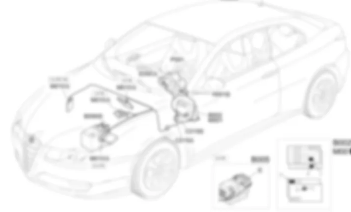
Location of components - CODE - Alfa Romeo GT 2.0 JTS
Components - CODE - Alfa Romeo GT 2.0 JTS
| Component code | Name | Assembly reference |
| B1 | JUNCTION UNIT | - |
| B2 | JUNCTION UNIT UNDER DASHBOARD | |
| B5 | MAXI FUSE-1 BOX | - |
| B99 | MAXIFUSE BOX ON BATTERY | |
| C15 | FACIA EARTH, DRIVER''S SIDE | - |
| E50 | INSTRUMENT PANEL | |
| H1 | IGNITION SWITCH | |
| M1 | BODY COMPUTER | |
| M10 | ENGINE MANAGEMENT ECU | 1056B |
| M10 | ENGINE MANAGEMENT ECU | |
| P91 | AERIAL FOR FIAT-CODE |
Description - CODE - Alfa Romeo GT 2.0 JTS
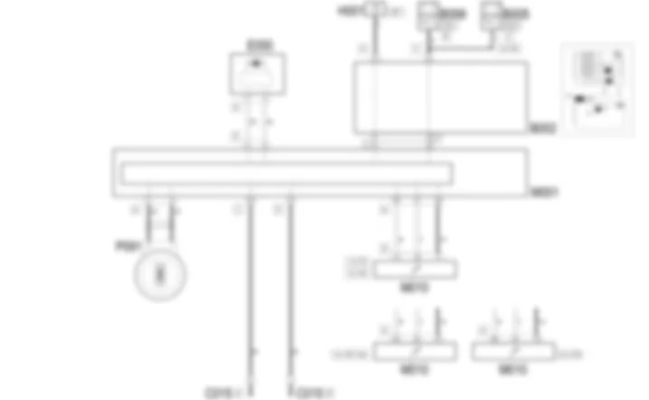
To increase the protection against theft attempts, an electronic immobiliser system known as the ALFA ROMEO CODE system is adopted.The keys are equipped with an electronic transponder which transmits a coded signal to a special electronic control unit in the Body Computer. This allows the engine to be started if the code is recognised.The code used in the communication, which takes place via aerial, changes each time the car is started up (rolling code). The code cannot therefore be reproduced, even with electronic scanners.The main function of the Code control unit is to identify the code in the ignition key. The control unit contains a secret code which is used to communicate with the key Transponder. The body computer contains all enabled key codes in its memory, together with the code used in the communication between the body computer and the engine management unit. When the key is turned to MAR for for the first time, if the key is identified correctly, the code is transferred to the engine management unit and is then indelibly linked to the body computer.The two units communicate via a two-way serial line.The function also allows status to be displayed via activation of a warning light (ALFA ROMEO CODE warning light) in the instrument panel and connected via the CAN network.For more details.
Functional description - CODE - Alfa Romeo GT 2.0 JTS
The CODE unit inside Body ComputerM1 is supplied from the battery from the line of maxifuse CPL B99 (B5 for the 3.2 V6 engine) pin 18 of connector F, while the ignition-operated power supply (INT) reaches pin 9. The line leading from pin 29 of connector A ofM1 is a serial line connected to the engine management unit M10 which is responsible for the communication required for identifying the key and exchanging codes. The aerial of CODE deviceP91 is connected via two leads to the CODE unit of M1, at pins 4 and 5 of connector A; The aerial is located coaxially on the ignition switch so that it can register key insertion and activation.Body ComputerM1 is linked to instrument panel E50, via the CAN line to manage the CODE failure warning light.

