Wiring diagram - HEADLAMP AGLINMENT CORRECTOR - Alfa Romeo GT 3.2 V6
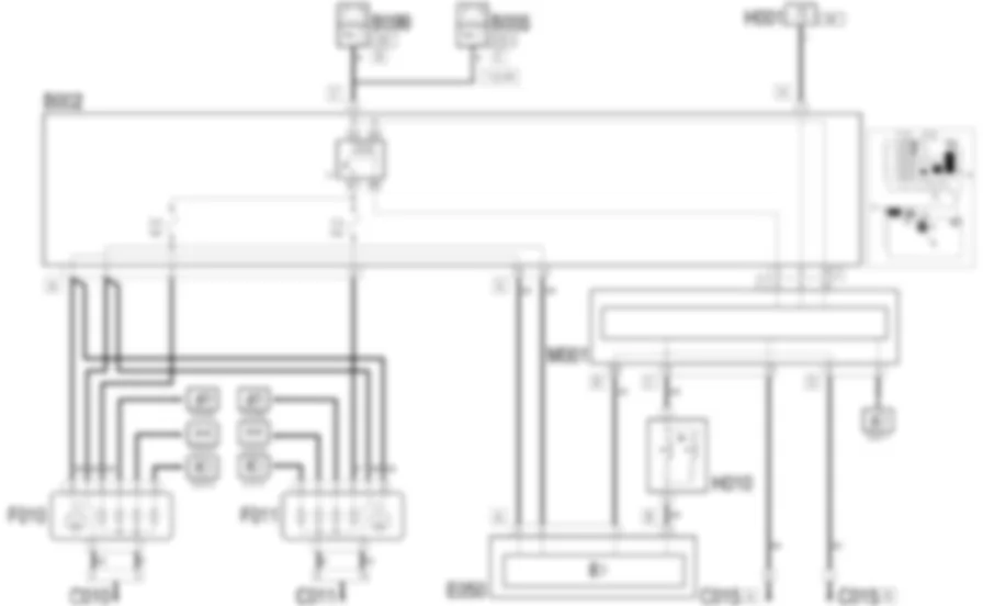
Components - HEADLAMP AGLINMENT CORRECTOR - Alfa Romeo GT 3.2 V6
| Component code | Name | Assembly reference |
| B1 | JUNCTION UNIT | - |
| B2 | JUNCTION UNIT UNDER DASHBOARD | |
| B5 | MAXI FUSE-1 BOX | - |
| B99 | MAXIFUSE BOX ON BATTERY | |
| C10 | FRONT LEFT EARTH ( FRONT ) | - |
| C11 | RIGHT FRONT EARTH ( FRONT ) | - |
| C15 | FACIA EARTH, DRIVER''S SIDE | - |
| D105 | AXIS CORRECTION REAR POTENTIOMETER COUPLING | - |
| D97 | SHORT CIRCUITING COUPLING | - |
| E50 | INSTRUMENT PANEL | |
| F10 | LEFT HEADLAMP ( FRONT ) | |
| F11 | RIGHT HEADLAMP | |
| H1 | IGNITION SWITCH | |
| H10 | CONTROLS FOR HEADLAMP ALIGNMENT INSTRUMENT LIGHTING ADJUSTMENT ( FACIA ) | |
| K1 | HEADLAMP ALIGNMENT FRONT POTENTIOMETER | |
| K2 | HEADLAMP AGLINMENT REAR POTENTIOMETER ( CONNECTORS ) | |
| M1 | BODY COMPUTER |
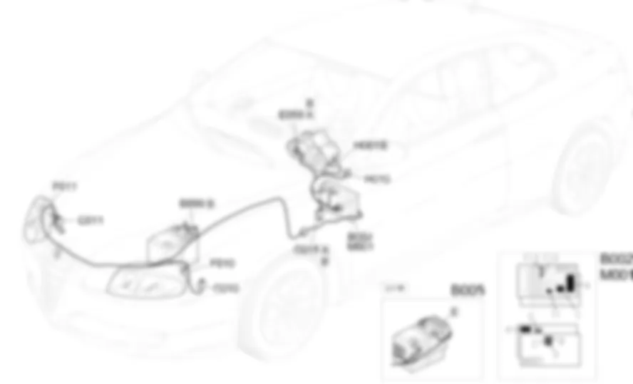
Location of components - HEADLAMP AGLINMENT CORRECTOR - Alfa Romeo GT 3.2 V6
Components - HEADLAMP AGLINMENT CORRECTOR - Alfa Romeo GT 3.2 V6
| Component code | Name | Assembly reference |
| B1 | JUNCTION UNIT | - |
| B2 | JUNCTION UNIT UNDER DASHBOARD | |
| B5 | MAXI FUSE-1 BOX | - |
| B99 | MAXIFUSE BOX ON BATTERY | |
| C10 | FRONT LEFT EARTH ( FRONT ) | - |
| C11 | RIGHT FRONT EARTH ( FRONT ) | - |
| C15 | FACIA EARTH, DRIVER''S SIDE | - |
| D105 | AXIS CORRECTION REAR POTENTIOMETER COUPLING | - |
| D97 | SHORT CIRCUITING COUPLING | - |
| E50 | INSTRUMENT PANEL | |
| F10 | LEFT HEADLAMP ( FRONT ) | |
| F11 | RIGHT HEADLAMP | |
| H1 | IGNITION SWITCH | |
| H10 | CONTROLS FOR HEADLAMP ALIGNMENT INSTRUMENT LIGHTING ADJUSTMENT ( FACIA ) | |
| K1 | HEADLAMP ALIGNMENT FRONT POTENTIOMETER | |
| K2 | HEADLAMP AGLINMENT REAR POTENTIOMETER ( CONNECTORS ) | |
| M1 | BODY COMPUTER |
Description - HEADLAMP AGLINMENT CORRECTOR - Alfa Romeo GT 3.2 V6
The headlamp beam orientation in accordance with the load is adjusted via the adjustment device located directly in the headlamps; it tilts them as appropriate in order to lower the light beam if the vehicle is particularly laden, and raises it when the load decreases.
Functional description - HEADLAMP AGLINMENT CORRECTOR - Alfa Romeo GT 3.2 V6
The dipped beam activation signal is sent to pin 4 of connector D of the Body ComputerM1from the stalk unitH5.The Body ComputerM1controls the supply to the dipped beam headlamps, sending an earth signal to the unit under the dashboardB2- from pin 8 of connector F ofM1- which energizes the relay T1; this supplies the dipped beam headlamps and gives enablement to the headlamp adjustment motorsF10(left) andF11(right).The headlamp adjustment control, located in the unitH10, sends a control signal - when the relevant buttons are pressed - to the instrument panelE50- pin 11 of connector B: the internal logic of E50 then sends (with dipped beam lights on) the supply to the motors from pin 5 of connector A, while pin 6 of connector A receives the reference signal.

