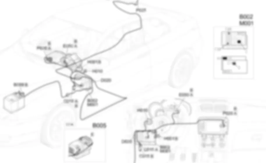
Wiring diagram - CONNECT - Alfa Romeo GT 3.2 V6
Components - CONNECT - Alfa Romeo GT 3.2 V6
| Component code | Name | Assembly reference |
| B1 | JUNCTION UNIT | - |
| B2 | JUNCTION UNIT UNDER DASHBOARD | |
| B5 | MAXI FUSE-1 BOX | - |
| B99 | MAXIFUSE BOX ON BATTERY | |
| C15 | FACIA EARTH, DRIVER''S SIDE | - |
| D20 | REAR DASHBOARD COUPLING ( REAR ) | - |
| H1 | IGNITION SWITCH | |
| M1 | BODY COMPUTER | |
| P20 | RADIO | |
| P20 | RADIO | |
| P25 | AERIAL AMPLIFIER FEEDER ( REAR ) |
Location of components - CONNECT - Alfa Romeo GT 3.2 V6
Components - CONNECT - Alfa Romeo GT 3.2 V6
| Component code | Name | Assembly reference |
| B1 | JUNCTION UNIT | - |
| B2 | JUNCTION UNIT UNDER DASHBOARD | |
| B5 | MAXI FUSE-1 BOX | - |
| B99 | MAXIFUSE BOX ON BATTERY | |
| C15 | FACIA EARTH, DRIVER''S SIDE | - |
| D20 | REAR DASHBOARD COUPLING ( REAR ) | - |
| H1 | IGNITION SWITCH | |
| M1 | BODY COMPUTER | |
| P20 | RADIO | |
| P20 | RADIO | |
| P25 | AERIAL AMPLIFIER FEEDER ( REAR ) |
Description - CONNECT - Alfa Romeo GT 3.2 V6
The navigation system informs you of the vehicle''s position on the map (in relation to both urban and non-urban/motorway road networks), by showing it on the CONNECT display.In this way, the driver is taken to the desired destination, guided step-by-step by voice messages and visual information. The system also provides additional information for reaching services of general interest, such as hotels, car parks, restaurants, pharmacies, service stations, hospitals, ALFA ROMEO garages, railway stations, airports, etc.If present, the navigator is included in the integrated radio-telephone-navigator.(N.I.T = Nodo Info Telematico - Info Telematic Node). referred to as CONNECT
Functional description - CONNECT - Alfa Romeo GT 3.2 V6
The integrated radio-telephone-navigatorP20is supplied directly (7 of connector A) from the battery via the line of the fuse F39 of the unit under the dashboardB2and maxifuse CPL ofB99.The supply to the side lights on reaches pin 4 of connector A.Pins 1 and 3 of connector A receive the CAN line with which the radioP20is connected to the Body ComputerM1and the other nodes of the system.Pin 8 of connector A is earthed.The aerialP25is supplied from pin 5 of connector A. The aerial containing the GPS reception device is connected to the navigator module by means of the specific coaxial cable.Connector B sends out cables carrying signals to the speakers through which the voice messages are sent:The ''MODE'' buttons of theH10controls unit are supplied by the line (INT) protected by the fuse F39 of control unitB2, and send the command to the instrument panelE50, pin 16 of connector B.The instrument panelE50is in turn connected via the CAN network to the Body ComputerM1and the integrated radio-telephone-navigatorP20.


