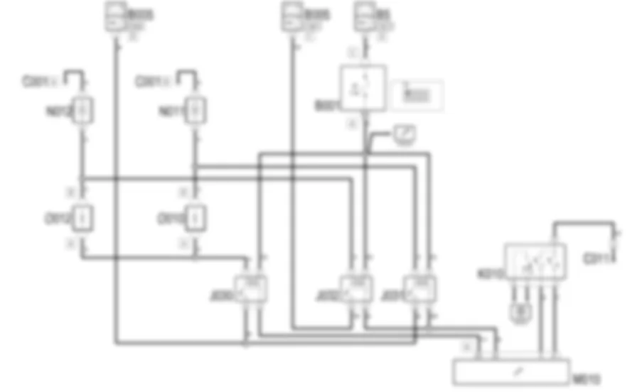
Wiring diagram - ENGINE COOLING - Alfa Romeo GT 3.2 V6
Components - ENGINE COOLING - Alfa Romeo GT 3.2 V6
| Component code | Description | Reference to the assembly |
| B1 | JUNCTION UNIT | |
| B1 | JUNCTION UNIT | |
| B5 | MAXI FUSE-1 BOX | - |
| B99 | MAXIFUSE BOX ON BATTERY | |
| C1 | BATTERY EARTH | - |
| C11 | RIGHT FRONT EARTH ( FRONT ) | - |
| H1 | IGNITION SWITCH | |
| J30 | ENGINE FAN 1ST SPEED RELAY ( FRONT ) | - |
| J31 | FAN 2ND SPEED RELAY | - |
| J32 | FAN 2ND SPEED RELAY | - |
| K10 | 4 STAGE PRESSURE SWITCH ( FRONT ) | |
| M10 | ENGINE MANAGEMENT ECU | Op. 1056B ALIMENTAZIONE MULTI-POINT INJECTION (MPI) |
| M10 | ENGINE MANAGEMENT ECU | |
| N11 | ENGINE FAN MOTOR - 1 | |
| N12 | ENGINE FAN MOTOR - 2 | |
| O10 | ENGINE FAN ADJUSTMENT RESISTOR - 1 | |
| O12 | ENGINE FAN ADJUSTMENT RESISTOR -2 | |
Component location - ENGINE COOLING - Alfa Romeo GT 3.2 V6
Components - ENGINE COOLING - Alfa Romeo GT 3.2 V6
| Component code | Description | Reference to the assembly |
| B1 | JUNCTION UNIT | |
| B1 | JUNCTION UNIT | |
| B5 | MAXI FUSE-1 BOX | - |
| B99 | MAXIFUSE BOX ON BATTERY | |
| C1 | BATTERY EARTH | - |
| C11 | RIGHT FRONT EARTH ( FRONT ) | - |
| H1 | IGNITION SWITCH | |
| J30 | ENGINE FAN 1ST SPEED RELAY ( FRONT ) | - |
| J31 | FAN 2ND SPEED RELAY | - |
| J32 | FAN 2ND SPEED RELAY | - |
| K10 | 4 STAGE PRESSURE SWITCH ( FRONT ) | |
| M10 | ENGINE MANAGEMENT ECU | Op. 1056B ALIMENTAZIONE MULTI-POINT INJECTION (MPI) |
| M10 | ENGINE MANAGEMENT ECU | |
| N11 | ENGINE FAN MOTOR - 1 | |
| N12 | ENGINE FAN MOTOR - 2 | |
| O10 | ENGINE FAN ADJUSTMENT RESISTOR - 1 | |
| O12 | ENGINE FAN ADJUSTMENT RESISTOR -2 | |
Description - ENGINE COOLING - Alfa Romeo GT 3.2 V6
The radiator and air conditioner condenser cooling system consists of two electric fans operated in parallel at two different speeds:the first speed is activated at an initial engine coolant temperature level or a certain air conditioning refrigerant fluid pressure;the second speed is engaged at a higher temperature or pressure.
The fans are operated by means of three specific relays located near the engine compartment junction unit.The supply line for the fans is protected by two special MAXIFUSES.
Operational description - ENGINE COOLING - Alfa Romeo GT 3.2 V6
The relays J30, J31and J32located next to the engine management control unit manage the engagement of the two fans N11and N12at two speeds: the coils are supplied by the line for fuse F6 of the engine compartment junction unit B1A.The relays are energized by an earth signal coming from the engine management control unit M10.If the engine coolant reaches an initial temperature level, or the 4 stage pressure switch K10signals to the control unit M10pin 9 of connector A - that the initial pressure level has been reached, then the control unit M10sends a signal from pin 50 of connector A to the 1st speed relay J30, which then sends the power supply to the fan N11via the additional resistance O10and to the fan N12via the additional resistance O12: the two fans turn at the first speed (slow).If the engine coolant reaches a higher temperature level, or the 4 stage pressure switch K10signals to the control unit M10pin 41 of connector A that the higher pressure level has been reached, then the control unit M10sends a signal from pin 62 of connector A to the two 2nd speed relays J31and J32, which then send the power supply to the fan N11and to the fan N12directly: the two fans turn at the maximum speed.Engine compartment junction unit
B1A
B1A
B1A
B1B
B1B
B1B
B1C
B1C
B1C
B1D
B1E
B1E
B1X
B1X
MAXI FUSE box
B5A
B5B
B5C
B5D
B5E
B5F
Maxifuse box on battery
B99A
B99A
B99B
B99D
Battery earth
C1A
C1A
C1A
C1B
C1C
Right front earth
C11
C11
C11
Ignition switch
H1A
H1A
H1B
Engine fan 1st speed relay
J30
Engine fan 2nd speed relay
J31
Engine fan 2nd speed relay
J32
4 stage pressure switch
K10
K10
K10
Engine management control unit
M10A
M10A
M10A
M10B
M10B
M10B
Engine electric fan motor
N11
N11
N11
Engine fan motor 2
N12
Engine fan adjustment resistor
O10A
O10A
O10A
O10B
O10B
O10B
Engine fan adjustment resistor 2
O12A
O12B


