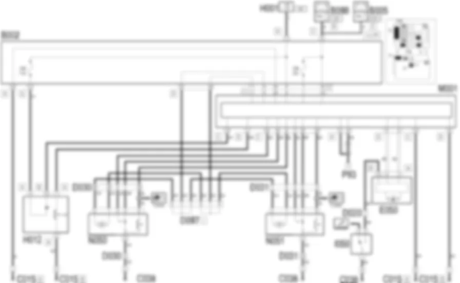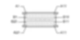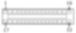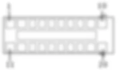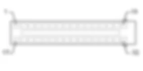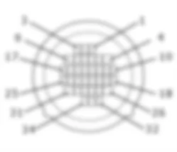
Wiring diagram - CENTRAL LOCKING - Alfa Romeo GT 1.8 T.SPARK
Components - CENTRAL LOCKING - Alfa Romeo GT 1.8 T.SPARK
| Component code | Name | Assembly reference |
| B1 | JUNCTION UNIT | - |
| B2 | JUNCTION UNIT UNDER DASHBOARD | |
| B5 | MAXI FUSE-1 BOX | - |
| B99 | MAXIFUSE BOX ON BATTERY | |
| C15 | FACIA EARTH, DRIVER''S SIDE | - |
| C38 | EARTH ON TUNNEL | - |
| D30 | REAR COUPLING FOR /FRONT DOOR. DRIVER''S SIDE | - |
| D31 | RIGHT FRONT DOOR REAR COUPLING/. | - |
| D97 | SHORT CIRCUITING COUPLING | - |
| E50 | INSTRUMENT PANEL | |
| H1 | IGNITION SWITCH | |
| H12 | HAZARD WARNING LIGHTS, FOG LIGHTS, REAR FOG LAMPS CONTROL | |
| M1 | BODY COMPUTER | |
| N50 | RIGHT FRONT DOOR LOCK LEFT | |
| N51 | RIGHT FRONT DOOR LOCK MOTOR | |
| P93 | RECEIVER AERIAL FOR ALARM AND CENTRAL LOCKING ( FRONT ) | - |
Location of components - CENTRAL LOCKING - Alfa Romeo GT 1.8 T.SPARK
Components - CENTRAL LOCKING - Alfa Romeo GT 1.8 T.SPARK
| Component code | Name | Assembly reference |
| B1 | JUNCTION UNIT | - |
| B2 | JUNCTION UNIT UNDER DASHBOARD | |
| B5 | MAXI FUSE-1 BOX | - |
| B99 | MAXIFUSE BOX ON BATTERY | |
| C15 | FACIA EARTH, DRIVER''S SIDE | - |
| C38 | EARTH ON TUNNEL | - |
| D30 | REAR COUPLING FOR /FRONT DOOR. DRIVER''S SIDE | - |
| D31 | RIGHT FRONT DOOR REAR COUPLING/. | - |
| D97 | SHORT CIRCUITING COUPLING | - |
| E50 | INSTRUMENT PANEL | |
| H1 | IGNITION SWITCH | |
| H12 | HAZARD WARNING LIGHTS, FOG LIGHTS, REAR FOG LAMPS CONTROL | |
| M1 | BODY COMPUTER | |
| N50 | RIGHT FRONT DOOR LOCK LEFT | |
| N51 | RIGHT FRONT DOOR LOCK MOTOR | |
| P93 | RECEIVER AERIAL FOR ALARM AND CENTRAL LOCKING ( FRONT ) | - |
Description - CENTRAL LOCKING - Alfa Romeo GT 1.8 T.SPARK
The door locks are operated simultaneously by:the key;the door handles;the button on the dashboard;the remote control.
Lock operation is managed by the Body Computer, which controls:the actual state of the locks by means of the signals which arrive from the switches located on the locks themselves (signals also used for timing the lights): in this way, the ''lock'' command is only issued when all the doors are properly closed and the locks released; conversely, the ''release'' command is only issued when the locks are locked;the switch position. If this position does not agree with the action carried out (e.g. if after the lock command a door is open), a repulsion command is issued, i.e. the opposite manoeuvre is carried out to realign all the locks.several consecutive and complete lock/release manoeuvres: if the control unit detects at least 10-11 manoeuvres within 25 seconds - the system cuts in to limit the manoeuvres: the system remains inhibited in the unlock position for 30 secondsif the battery voltage falls below 8-10 V during a lock/release operation, the system suspends the operation. If battery voltage is lower than 8 V at the outset, no command is issued.
The signals coming from the door (and boot) open switches together - when the ignition is on - switch on the specific warning light on the instrument panel.The remote control receiver aerial is connected directly to the Body Computer which contains the electronics of the receiver proper: the remote control in the key has two separate buttons: one controls the door lock, the other the release (a third button controls the boot release).If within 60 seconds from the lock release command issued via the remote control, the user has not shown his intention to take possession of the car (opening of doors and/or boot and ignition turned on), the locks are automatically LOCKED.The door lock/release button is located on the central panel: if the doors are closed, pressing the button releases them; vice versa if they are open, they are locked; an LED at the back of the button also comes on.The doors are automatically released if the inertia switch is activated: the instrument panel receives a signal from the switch, lights up the relevant warning light and communicates the activation to the Body Computer via the CAN network.The door lock circuit is protected by a special fuse located in the unit under the dashboard.
Functional description - CENTRAL LOCKING - Alfa Romeo GT 1.8 T.SPARK
The door lock command, inside the Body ComputerM1- pin 1 of connector F - has the supply line protected by fuse F38 in the unit under the dashboardB2; also has a dedicated earth connection: pin 20 of connector F.The Body Computer M1 receives as input:the ''lock'' signals from the handles (or key in the lock) at pins 24 (driver''s front door - N50) and 17 (front passenger''s door - N51) of connector E.the ''release'' signals from the handles (or key in the lock) at pins 34 (driver''s front door - N50) and 35 (front passenger''s door - N51) of connector E.the ''door open'' signals at pins 8 (driver''s door - N50) and 25 (front passenger''s door - N51) of connector E;the signal from the lock/release button, located in the controls unit H12 , at pin 2 of connector D; (the button is lit when the doors are locked by the ignition-dependent line (INT) of fuse F49 of unit B2 );the signals coming from the aerial-receiver P93 , which is connected to pins 21 and 31 of connector A.
In accordance with the control logic described above, the Body ComputerM1 controls the lock motors of the driver''s front door N50 and front passenger''s door N51, from pins 10 and 11 of connector F.Body ComputerM1connects to instrument panelE50via the CAN line. The computer sends a signal that turns on the door open warning light when required.The intervention of the inertia switchI50 is signalled to pin 12 of connector A of E50 via the CAN line, the instrument panel E50 is connected to the Body Computer M1 and this signal causes the unlocking of the doors.Engine compartment junction unit
B1A
B1A
B1A
B1B
B1B
B1B
B1C
B1C
B1C
B1D
B1E
B1E
B1X
B1X
Junction unit under dashboard
B2A
B2A
B2A
B2A
B2A
B2A
B2B
B2B
B2C
B2C
B2D
B2E
B2F
B2G
B2H
MAXI FUSE box
B5A
B5B
B5C
B5D
B5E
B5F
Maxifuse box on battery
B99A
B99A
B99B
B99D
Facia earth, driver's side
C15A
C15B
C15C
Earth on centre tunnel
C38
Rear coupling for front door driver's side
D30
D30
D30
Front passenger door rear coupling
D31
D31
D31
Short circuiting coupling
D97A
D97A
D97A
D97C
D97D
D97E
D97G
D97H
D97I
D97M
Instrument panel
E50A
E50B
Ignition switch
H1A
H1A
H1B
Hazard warning lights fog lights rear fog lamps control
H12A
H12B
Body computer
M1A
M1A
M1A
M1A
M1A
M1A
M1B
M1C
M1D
M1E
M1F
M1G
Front driver's door lock geared motor
N50
Passenger side front door lock geared motor
N51
Receiver aerial for alarm and central locking
P93


