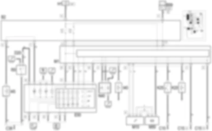
Wiring diagram - INSTRUMENT PANEL - Alfa Romeo GT 1.8 T.SPARK
Components - INSTRUMENT PANEL - Alfa Romeo GT 1.8 T.SPARK
| Component code | Name | Assembly reference |
| Engine compartment junction unit | - |
| Junction unit under dashboard | |
| MAXI FUSE box | - |
| Maxifuse box on battery | |
| Front left earth | - |
| Facia earth, driver''s side | - |
| Earth on centre tunnel | - |
| Front dashboard coupling | - |
| Front/engine connection | - |
| Rear dashboard coupling | - |
| Instrument panel | |
| Ignition switch | |
| Handbrake switch | |
| Seat belts warning light switch | |
| Inertial switch | |
| Left brake pad wear sensor switch | |
| Brake fluid level sensor (switch) | |
| Engine oil temperature sensor | |
| Engine oil level sensor | |
| Body computer | |
| Engine management control unit | 1056B |
| Engine management control unit | |
| ABS control unit | |
| Fuel pump and sender unit | |
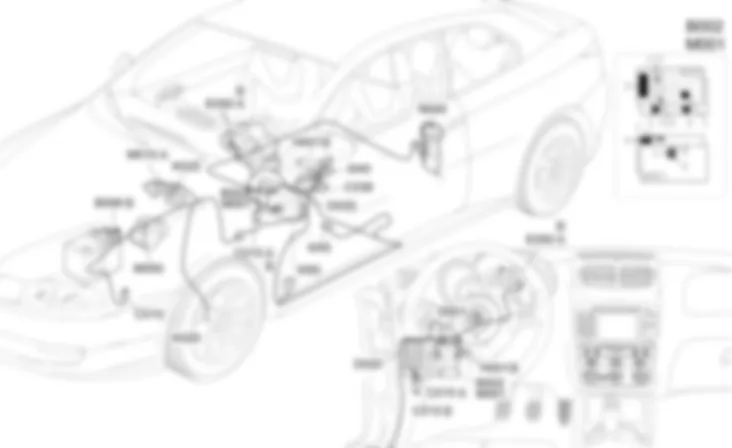
Location of components - INSTRUMENT PANEL - Alfa Romeo GT 1.8 T.SPARK
Components - INSTRUMENT PANEL - Alfa Romeo GT 1.8 T.SPARK
Functional description - INSTRUMENT PANEL - Alfa Romeo GT 1.8 T.SPARK
The ignition-operated power supply (INT) of the instrument panelE50reaches pin 1 of connector A through the line of fuse F37 of the unit under the dashboardB2; the direct supply reaches pin 2 of connector A through the line of fuse F53 of the unit under the dashboardB2; pin 7 of connector A is earthed (earth controlled by the Body ComputerM1).The instrument panelE50 is connected from pins 3 and 4 of connector A to the Body Computer M1 and via the latter to the whole CAN network: via CAN the signal for the electronic speedometer arrives (coming from the ABS control unit M50): this signal is replicated from pin 37 of M50 to pin 17 of connector A of the Body Computer M1.The electronic rev counter receives the rpm signal coming via CAN from the engine management control unitM10.The fuel gauge is controlled in accordance with the signals coming from the fuel gauge sender unit located in the fuel pump assemblyN40- at pins 4 and 15 of the Body ComputerM1, and from here via CAN to the instrument panelE50.The seat belt warning light is controlled by a signal sent to pin 15 of connector A ofE50from switchI45.The inertia switch warning light is controlled in accordance with the signal which reaches pin 12 of connector A ofE50from the relevant switchI50(N.O. contact: the N.C. contact is the one which interrupts the operation of the petrol pump.The brake pad wear warning light is controlled in accordance with the signal which reaches pin 23 of connector A of the Body ComputerM1from the relevant sensorK20.The low brake fluid/handbrake applied warning light comes on through a signal from the handbrake switchI40, which reaches pin 24 of connector E of the Body ComputerM1, or from the signal from the low brake fluid level sensorK25, which reaches pin 18 of connector A ofM1.All these signals are transferred via CAN to the instrument panelE50.
Description - INSTRUMENT PANEL - Alfa Romeo GT 1.8 T.SPARK
The gauges and warning lights which form the instrument panel are grouped in a single instrument containing:electronic speedometerelectronic rev countercoolant temperature gauge, with overheating warning lightfuel gauge, with reserve warning lightwarning lights.
The instrument panel is a node on the CAN through which it exchanges information with the Body Computer and the other electronic units.Speedometer: the function displays the vehicle speed on the instrument panel: this information comes from the ABS control unit, via the Body Computer.Engine rpm: the function displays the engine rpm on the instrument panel, via the message sent on the CAN network from the engine management control unit.Odometer: this function displays and memorises the total mileage counter and trip recorder: the distance travelled information is processed by the Body Computer via a counter; the specific button located on the panel beside the steering wheel resets the trip recorder.Fuel gauge: the Body Computer receives the signal from the sensor integrated in the pump unit in the fuel tank and processes it so as to ensure appropriate filtering / damping to the instrument panel gauge, and also controls the lighting up of the ''reserve'' warning light.Engine water temperature: the function displays the water temperature on the instrument panel and lights up the water overheating warning light by means of the messages sent via the CAN network from the engine management control unit.Minimum engine oil pressure: the function lights up the minimum oil pressure warning light on the instrument panel via the message sent on the CAN network from the engine management control unit.Brake pad wear: the function lights up the specific warning light: the Body Computer detects the state of the brake pad wear associated with the presence of braking (signal from the brake pedal) which is prolonged (intermittent indications are ignored).Inertial switch state: the instrument panel receives a signal from the switch, lights up the relevant warning light and communicates the activation to the other nodes via the CAN network.Driver''s seat belt not fastened: the instrument panel receives a signal from the seat belt unfastened switch and lights up the relevant warning light.Handbrake on: the warning light relating to the handbrake state is controlled by the specific switch; in addition, if this signal is associated with a particular speed threshold being surpassed, an acoustic signal is activated: the signal is sent via the CAN from the Body Computer.Low brake fluid: the function lights up the ''low brake fluid level'' warning light on the instrument panel: the signal is sent via the CAN from the Body Computer.
Other warning lights are located on the instrument panel, but managed directly by other electronic units:Air Bag failure warning light;passenger Air Bag disablement warning light;i.e. failure warning light (EOBD)
The active matrix LCD also shows some commands or messages relating to the use of the radio, telephoneor navigatorcoming from the integrated radio-telephone-navigator.For more details.This diagram illustrates the operation of the warning lights not contained in other functions; the others are described and illustrated in the diagrams of the components to which they refer:side lights, lights failure (check)main beam headlampsturn signalsdoors openrechargingEOBD - injection system failureminimum oil pressure;engine overheatingCruise ControlCODE failureABS - EBD failureVDC on/failureAir Bag failurepassenger Air Bag disabledselected gears displaygearbox failure


