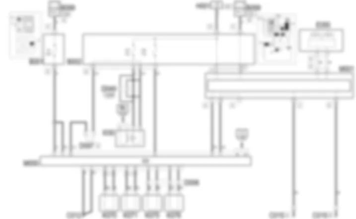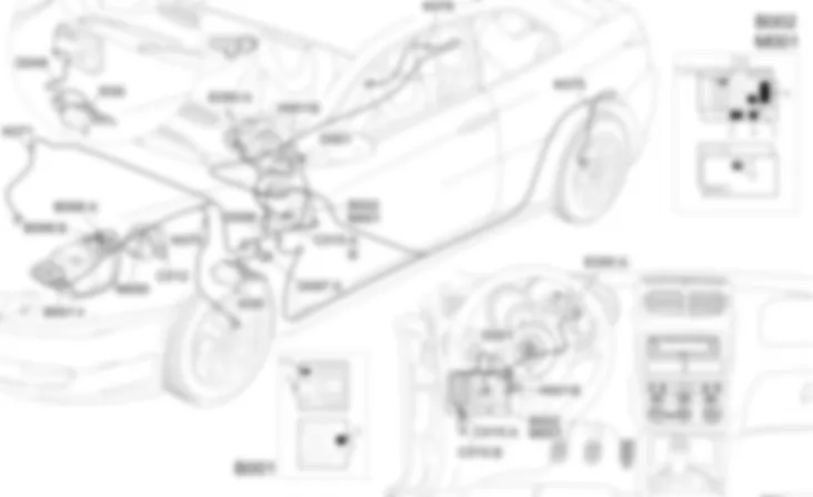
Wiring diagram - ABS - Alfa Romeo GT 1.8 T.SPARK
Components - ABS - Alfa Romeo GT 1.8 T.SPARK
| Component code | Description | Reference to the assembly |
| B1 | JUNCTION UNIT | |
| B2 | JUNCTION UNIT UNDER DASHBOARD | |
| B99 | MAXIFUSE BOX ON BATTERY | |
| C12 | ABS FRONT EARTH | - |
| C15 | FACIA EARTH, DRIVER''S SIDE | - |
| D6 | REAR / ENGINE COMPARTMENT JUNCTION | - |
| D49 | PEDAL ASSEMBLY JOIN | - |
| D97 | SHORT CIRCUITING COUPLING | - |
| E50 | ENGINE CONTROL AND MANAGEMENT SYSTEMS | |
| H1 | IGNITION SWITCH | |
| K70 | Left front wheel sensor for ABS | |
| K71 | Right front wheel sensor for ABS | |
| K75 | Left rear wheel sensor for ABS | |
| K76 | Right rear wheel sensor for ABS | |
| M1 | BODY COMPUTER | |
| M10 | ENGINE MANAGEMENT ECU | Op. 1056B ALIMENTAZIONE MULTI-POINT INJECTION (MPI) |
| M10 | ENGINE MANAGEMENT ECU | |
| M50 | ABS control unit |
Component location - ABS - Alfa Romeo GT 1.8 T.SPARK
Components - ABS - Alfa Romeo GT 1.8 T.SPARK
| Component code | Description | Reference to the assembly |
| B1 | JUNCTION UNIT | |
| B2 | JUNCTION UNIT UNDER DASHBOARD | |
| B99 | MAXIFUSE BOX ON BATTERY | |
| C12 | ABS FRONT EARTH | - |
| C15 | FACIA EARTH, DRIVER''S SIDE | - |
| D6 | REAR / ENGINE COMPARTMENT JUNCTION | - |
| D49 | PEDAL ASSEMBLY JOIN | - |
| D97 | SHORT CIRCUITING COUPLING | - |
| E50 | ENGINE CONTROL AND MANAGEMENT SYSTEMS | |
| H1 | IGNITION SWITCH | |
| K70 | Left front wheel sensor for ABS | |
| K71 | Right front wheel sensor for ABS | |
| K75 | Left rear wheel sensor for ABS | |
| K76 | Right rear wheel sensor for ABS | |
| M1 | BODY COMPUTER | |
| M10 | ENGINE MANAGEMENT ECU | Op. 1056B ALIMENTAZIONE MULTI-POINT INJECTION (MPI) |
| M10 | ENGINE MANAGEMENT ECU | |
| M50 | ABS control unit |
Description - ABS - Alfa Romeo GT 1.8 T.SPARK
The BOSCH 5.7 ABS electronic antilock braking system regulates the braking pressure transmitted to the wheels, preventing them from losing grip whatever the tyre and road conditions.The system is designed to be incorporated with the braking system (using the same hydraulic fluid) without preventing the operation of the actual braking system if the ABS fails.Four sensors, located on each of the four wheels, indicatae the speed of each wheel to the electronic control unit, recording any situations involving locking, slipping or loss of grip.In these situations, the control unit controls the solenoid valves which modulate the pressure in the hydraulic circuit, preventing the wheels from locking and restoring grip conditions for the vehicle which ensures optimum handling of the vehicle and excellent stopping distances.The sensors are the "active" type, supplied by the control unit; they consist of a magnetic resistive receiver with a magnetic codifier incorporated in the hub bearing so that the signal is less affected by electromagnetic interference and variations in temperature.The ABS control unit also controls the distribution of the braking load between the front and rear axles meaning that the mechanical load proportioning valve used previously can be dispensed with (EBD function: Electronic Brake Distribution ).The control unit is equipped with an autodiagnostic function: when an error in the ABS function is detected, the warning light comes on and, at the same time, the system is deactivated; in these conditions the vehicle brakes using the traditional system only.When the control unit detects an error which also affects the EBD function, it turns on the "ABS failure" warning light and the "low brake fluid and handbrake" warning light.
Operational description - ABS - Alfa Romeo GT 1.8 T.SPARK
The ABS electronic control unit M50receives a power supply (at pins 2 and 6) directly from the battery through the line protected by maxifuse F4 of the engine compartment junction unit B1.The ignition-controlled power supply (INT) arrives at pin 23 from the line protected by fuse F42 of the junction unit under the dashboard B2.The control unit is earthed at pins 1 and 5.The four sensors K70send wheel speed signals to pins 28-12, 15-16, 13-14 and 30-31 ofM50, K75, K76send speed signals for the wheels to pins 28-12, 15-16, 13-14, 30-31 of M50respectively.The brake pedal switch I30sends an enablement signal to pin 32 of junction unit M50: any intervention of the ABS is excluded unless the brake pedal is pressed; switch I30receives an ignition-operated supply (INT) from fuse F37 of junction unit B2.From pin 37 of M50a discrete speedometer signal sent to the Body Computer M1leaves; the same signal is replicated via the CAN.Via the CAN, the ABS control unit M50is connected - from pins 24 and 40 - to the Body Computer M1and to the instrument panel E50, to manage the "ABS failure" warning light and, if the problems involve the EBD function, the "low brake fluid level" and "handbrake" warning lightThe autodiagnostic data can be read by connecting to connector G of the Body Computer M1- pin 1: it receives the signals from pin 11 of control unit M50via the special diagnostic line.

