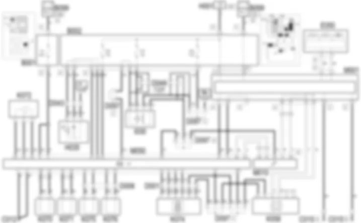
Wiring diagram - VDC - Alfa Romeo GT 1.8 T.SPARK
Components - VDC - Alfa Romeo GT 1.8 T.SPARK
| Component code | Name | Assembly reference |
| B1 | JUNCTION UNIT | - |
| B1 | JUNCTION UNIT | |
| B2 | JUNCTION UNIT UNDER DASHBOARD | |
| B5 | MAXI FUSE-1 BOX | - |
| B99 | MAXIFUSE BOX ON BATTERY | |
| C12 | ABS FRONT EARTH | - |
| C15 | FACIA EARTH, DRIVER''S SIDE | - |
| D1 | FRONT DASHBOARD COUPLING ( FRONT ) | - |
| D43 | DASHBOARD/CENTRE CONSOLE COUPLING | - |
| D97 | SHORT CIRCUITING COUPLING | - |
| E50 | INSTRUMENT PANEL | |
| H1 | IGNITION SWITCH | |
| H35 | SWITCHES ON TUNNEL ( CONNECTORS ) | |
| I30 | BRAKE PEDAL SWITCH ( FRONT ) | |
| K58 | STEERING SENSOR ( FRONT ) | |
| K70 | LEFT FRONT WHEEL SENSOR FOR ABS ( FRONT ) | |
| K71 | RIGHT. FRONT WHEEL SENSOR FOR ABS | |
| K72 | PRESSURE SENSOR VDC ( FRONT ) | |
| K74 | YAWING SENSOR | |
| K75 | LEFT REAR WHEEL SENSOR FOR ABS ( CONNECTORS ) | |
| K76 | RIGHT REAR WHEEL SENSOR FOR ABS ( CONNECTORS ) | |
| M1 | BODY COMPUTER | |
| M10 | ENGINE MANAGEMENT ECU | 1056B |
| M10 | ENGINE MANAGEMENT ECU | |
| M50 | ABS CONTROL UNIT ( FRONT ) |
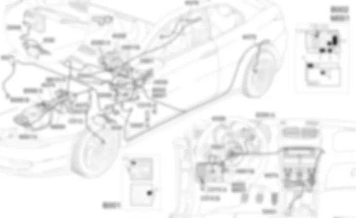
Location of components - VDC - Alfa Romeo GT 1.8 T.SPARK
Components - VDC - Alfa Romeo GT 1.8 T.SPARK
| Component code | Name | Assembly reference |
| B1 | JUNCTION UNIT | - |
| B1 | JUNCTION UNIT | |
| B2 | JUNCTION UNIT UNDER DASHBOARD | |
| B5 | MAXI FUSE-1 BOX | - |
| B99 | MAXIFUSE BOX ON BATTERY | |
| C12 | ABS FRONT EARTH | - |
| C15 | FACIA EARTH, DRIVER''S SIDE | - |
| D1 | FRONT DASHBOARD COUPLING ( FRONT ) | - |
| D43 | DASHBOARD/CENTRE CONSOLE COUPLING | - |
| D97 | SHORT CIRCUITING COUPLING | - |
| E50 | INSTRUMENT PANEL | |
| H1 | IGNITION SWITCH | |
| H35 | SWITCHES ON TUNNEL ( CONNECTORS ) | |
| I30 | BRAKE PEDAL SWITCH ( FRONT ) | |
| K58 | STEERING SENSOR ( FRONT ) | |
| K70 | LEFT FRONT WHEEL SENSOR FOR ABS ( FRONT ) | |
| K71 | RIGHT. FRONT WHEEL SENSOR FOR ABS | |
| K72 | PRESSURE SENSOR VDC ( FRONT ) | |
| K74 | YAWING SENSOR | |
| K75 | LEFT REAR WHEEL SENSOR FOR ABS ( CONNECTORS ) | |
| K76 | RIGHT REAR WHEEL SENSOR FOR ABS ( CONNECTORS ) | |
| M1 | BODY COMPUTER | |
| M10 | ENGINE MANAGEMENT ECU | 1056B |
| M10 | ENGINE MANAGEMENT ECU | |
| M50 | ABS CONTROL UNIT ( FRONT ) |
Description - VDC - Alfa Romeo GT 1.8 T.SPARK
The antilock braking and anti-slip regulation systems (BOSCH 5.7 ABS with ASR) modulate brake pressure sent to the wheels to prevent loss of grip under all tyre and road surface conditions by cutting in automatically whenever one or both drive wheels begin to slip.The system is designed to complement the normal mechanical braking system and not to replace it. In this way it ensures effective safety in the case of anomalies: the ABS uses the same fluid as the conventional mechanical braking system.Four sensors fitted to the four wheels inform the electronic control unit of wheel speed at every moment. In this way, they detect wheel lock, wheel slip and loss of grip.Under these conditions, the control unit sends specific instructions to solenoids that modulate hydraulic circuit pressure to eliminate lock and restore the car to within grip limits. This ensures the shortest possible stopping distance, without losing control of the steering.The sensors are active, i.e. they consist of a Hall-effect receiver that faces a magnetic coding device built into the hub bearing. Under these conditions, the signal is less influenced by electromagnetic interference and temperature.The control unit also controls brakeforce distribution over the rear axle and thus replaces the mechanical lload proportioning valve used previously (EBD function: Electronic Brake Distribution).The control unit is equipped with a self-diagnostic function: when an error occurs in the ABS system, a warning light is turned on and the system is simultaneously deactivated. Under these conditions, the car brakes using only the conventional system.When the control unit detects an error in the EBD function, it simultaneously turns on the ''insufficient brake fluid level'' and ''handbrake on'' warning light as well as the ABS warning light.
Functional description - VDC - Alfa Romeo GT 1.8 T.SPARK
The ABS electronic control unitM50 is supplied (at pins 2 and 6) directly by the battery via a line protected by maxifuse F4, housed in the engine compartment junction unit B1. The ignition-operated supply (INT/A) reaches pin 23 from the line protected by the fuse F42 of under facia control unitB2. The control unit is earthed via pins 1 and 5.The four sensorsK70, K71, K75, K76 send wheel speed signals to pins 28-12, 15-16, 13-14 and 30-31 of M50 respectively. When the brake pedal is pressed, the brake pedal switchI30 sends an enablement signal (N.O contact) to pin 32 of control unit M50: the ABS cannot intervene unless the brake pedal is pressed. The switchI30 is supplied when the ignition is switched on (INT) from fuse F37 of junction unit B2. When the pedal is released, the N.C. contact is sent to pin 20 of the control unitM50;this contact of switchI30 is supplied when the ignition is switched on (INT) from fuse F35 of junction unit B2.The ''ASR OFF'' control button on panelH35 sends a deactivation signal to pin 27 of M50, while pin 18 relays a signal that turns on a led on panel H35 when the system is off. Pin 37 ofM50 emits a discrete speed signal that is sent to Body Computer M1; the same signal is also copied via the CAN network.Steering sensorK58 is supplied by ABS control unit M50 at pin 39 and receives a reference earth from pin 21: the signal that detects sudden changes in steering direction is sent via the CAN line to engine control unit M1 and ABS control unit M50. Yaw sensorK74 is supplied from ABS control unit M50 at pin 39, while it receives a reference earth from pin 21: control and command signals are exchanged with ABS control unit M50, at pins 8, 9, 10 and 41. Pressure sensorK72 is supplied from ABS control unit M50 at pin 42, while it receives a reference earth from pin 25: the pressure detection signal is sent to pin 26 of ABS control unit M50. Via the CAN line, pins 24 and 40 of ABS control unitM50 connect to Body Computer M1 and and instrument panel E50 to control the ABS warning light and - if the problem lies in the EBD function - the low brake fluid level and handbrake warning lights. The VDC and ASR functions manage the relevant warning light as described previously.Self-diagnostic data can be read by connecting to connector G of Body ComputerM1 - pin 1: it receives signals from pin 11 of control unit M50 via a special diagnostic line.

