Wiring Diagram - CAN CONNECTION LINES - Fiat PANDA 1.2 8v
COMPONENTS - CAN CONNECTION LINES - Fiat PANDA 1.2 8v
| Component code | Description | Reference to the assembly |
| B1 | JUNCTION UNIT | |
| B2 | Junction unit under dashboard | |
| D21 | DASHBOARD/AIR CONDITIONING-HEATER CONNECTION | - |
| D97 | SHORT CIRCUITING COUPLING | - |
| E50 | ENGINE CONTROL AND MANAGEMENT SYSTEMS | |
| M1 | BODY COMPUTER | |
| M10 | ENGINE MANAGEMENT ECU | |
| M50 | ABS control unit | |
| M70 | Climate control system control unit | |
| M94 | Radio Receiver Node | - |
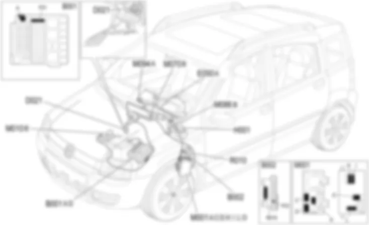
Component location - CAN CONNECTION LINES - Fiat PANDA 1.2 8v
COMPONENTS - CAN CONNECTION LINES - Fiat PANDA 1.2 8v
| Component code | Description | Reference to the assembly |
| B1 | JUNCTION UNIT | |
| B2 | Junction unit under dashboard | |
| D21 | Dashboard/air conditioning-heater coupling | - |
| D97 | Short circuit coupling | - |
| E50 | ENGINE CONTROL AND MANAGEMENT SYSTEMS | |
| M1 | BODY COMPUTER | |
| M10 | ENGINE MANAGEMENT ECU | |
| M50 | ABS control unit | |
| M70 | Climate control system control unit | |
| M94 | Radio Receiver Node | - |
Description - CAN CONNECTION LINES - Fiat PANDA 1.2 8v
This vehicle is equipped with a CAN (Controller Area Network) system of electrical connections: it involves a software and hardware solution which is designed to manage the resources on the vehicle efficiently allowing:the sharing of information between the various electronic units;the intergration of several electronic units through one network;a high network information exchange speed;advantages in economic terms because there is a considerable reduction in the wiring/connectors inside the vehicle;superior standards in terms of quality and reliability.
The advantage of using a CAN system stems from the fact that communication takes place between numerous control units and consequently the number of signals to be managed is very high.The system uses a low speed CAN serial network (B CAN) and a high speed network (C CAN) for communication between Nodes.767NODES are all the electrical/electronic devices and control units that contain a specific interface (NETWORK INTERFACE) that allow data, information and signals travelling via the CANs to be transmitted and received.The B-CAN (low speed) network comprises 2 electrical wires, one White/Pink shown in the wiring diagram as the B CAN-A cable and one Black/Pink one shown in the wiring diagram as the B CAN-B cable.The transmission of information on this pair of wires takes place by means of 2 voltage levels, one High and one Low, associated with the B CAN-A cable and the B CAN-B cable respectively.The C-CAN (high speed) network comprises 2 electrical wires, one Green shown in the wiring diagram as the CAN-H cable and one Brown shown in the wiring diagram as the CAN-L cable.The transmission of information on this pair of wires takes place by means of 2 voltage levels, one High and one Low, associated with the C CAN-H cable and the C CAN-L cable respectively.Shared information for the dynamic control of the vehicle is transferred via the C CAN whilst the B CAN manages the standard bodywork functions.The gateway for communication between the C CAN and B CAN is located in the body computer node.For more details on the operating principle of the B CAN and C CAN networks, consult the DESCRIPTION and OPERATION section.
Operational Description - CAN CONNECTION LINES - Fiat PANDA 1.2 8v
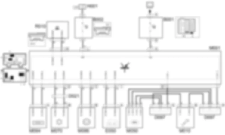
The electronic control units that communicate via the CAN (B CAN and C CAN) exchange information by means of the body computer node M001.The body computer node receives a direct battery supply at pin 1 connector A and an ignition-operated supply at pin 1 connector L.The body computer node M001 assumes the role of "information collector" for the information coming from the various nodes, thereby allowing the exchange of data between the B CAN and C CAN.Connection via B CANFrom connector O, the body computer node receives/sends signals coming:from the radio receiver node M094, pin 1, 3 connector A;from the climate control system control unit M070, pin 9, 10 connector B.
From connector I, the body computer node receives/sends signals coming:from the instrument panel E050, pin 8, 9 connector A.
From connector H, the body computer node receives/sends signals to the diagnostic socket R010, pin 6, 14.
From connector C, the body computer node receives/sends signals coming:from the electric steering control unit M086, pin 5, 10 connector B;
Connection via C CANThe nodes which communicate with one another via the C CAN are: body computer node M001, from pin 11, 12 connector D;the engine management control unit M010, from pin 52, 36 connector B;ABS control unit M050 from pins 14, 15, 25, 26;
Communication between the variousnodes on the C CAN-L line is managed by the short circuit coupling D097 connector G, whilst for the C CAN-H line it is managed by coupling D097 connector H.lThe two coupling connect the various nodes in such a way that the same information is transmitted to all the nodes connected to the same coupling.JUNCTION UNIT
B001A
B001D
B001D
B001D
B001D
B001D
B001D
B001D
JUNCTION UNIT UNDER DASHBOARD
B002
INSTRUMENT PANEL
E050A
E050B
BODY COMPUTER
M001A
M001A
M001A
M001B
M001B
M001B
M001C
M001C
M001C
M001C
M001D
M001D
M001E
M001E
M001F
M001F
M001F
M001G
M001H
M001H
M001I
M001L
M001L
M001M
M001M
M001N
M001O
M001O
M001P
ENGINE MANAGEMENT ECU
M010A
M010A
M010A
M010B
M010B
M010B
M010B
M010B
M010B
M010B
M010B
M010C
M010C
M010C
ABS CONTROL UNIT
M050
M050
M050
CLIMATE CONTROL SYSTEM CONTROL UNIT
M070A
M070B
RADIO RECEIVER NODE
M094A
M094A
M094B
M094C
M094D
M094E


