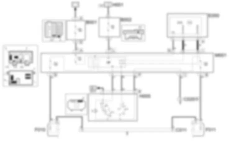
Wiring diagram - DIPPED HEADLAMPS - Fiat PANDA 1.3 JTD 16v
COMPONENTS - DIPPED HEADLAMPS - Fiat PANDA 1.3 JTD 16v
| Component code | Description | Reference to the assembly |
| B1 | engine compartment junction unit | |
| C11 | Right front earth | - |
| C20 | Passenger dashboard earth | - |
| E50 | Instrument panel | |
| F11 | Right headlamp | |
| H5 | Steering column switch unit | |
Component location - DIPPED HEADLAMPS - Fiat PANDA 1.3 JTD 16v
COMPONENTS - DIPPED HEADLAMPS - Fiat PANDA 1.3 JTD 16v
| Component code | Description | Reference to the assembly |
| B1 | engine compartment junction unit | |
| C11 | Right front earth | - |
| C20 | Passenger dashboard earth | - |
| E50 | Instrument panel | |
| F11 | Right headlamp | |
| H5 | Steering column switch unit | |
Description - DIPPED HEADLAMPS - Fiat PANDA 1.3 JTD 16v
The vehicle is equipped with two specific dipped beam headlamps.The dipped beams are activated by turning a wheel on the stalk switch to the next position after the side light setting (second position).The circuit is protected by two specific fuses, housed inside the body computer node, used individually for each light cluster.The "Follow me home" function allows the dipped headlamps and the side lights to remain on even after the engine has been switched off for a period of 30 seconds or multiples thereof in the following conditions:ignition key OFFactivating the flasher lever within 2 seconds of the ignition key being turned OFF (increases of 30 secs. up to a maximum of 210 secs.)
The programming of the function is cancelled by operating the flasher lever for more than 2 secs.The instrument panel displays the function activation time.For more details see the function dealt with the in DESCRIPTION AND OPERATION section.
Operational description - DIPPED HEADLAMPS - Fiat PANDA 1.3 JTD 16v
The command for switching on the dipped headlamps is sent from the steering column switch unit H005 by turning the levers A and B (both switches have the same synchronous movement) to position 2.The body computer node M001:receveis the negative signal (reference to earth C020) at pin 2 (side lights) and at pin 7 (dipped headlamps) connector P.
767Earth C020 is secured to the passenger compartment floor and is positioned near the right front wheel arch (footwell area).Having received the signal, the side lights (see wiring diagram E2010) and the dipped headlamps are switched on:from pins 7 and 8 connector B the dipped headlamps housed in the front light clusters F010 and F011 are supplied;
The two lines are protected by fuses F13 (left branch) and F12 (right branch) housed inside the actual body computer node.767The supply lines protected by fuses F12, F13 are operated by a relay integrated in the body computer node.The command for activating the follow me home function is sent from the steering column switch unit H005 via button D (flasher).The body computer node M001:receives the negative signal (with reference to earth C020 connector B) at pin 5 connector P
Having received the signal, the dipped headlamps are switched on:from pins 7 and 8 connector B the dipped headlamps housed in the front light clusters F010 and F011 are supplied;
Pressing the levers D (flasher) for more than two seconds deactivates the function.The body computer communicates, from pins 35, 36 connector I, via the CAN, with the instrument panel E050 (for more details), controlling the switching on of the "side lights", "lights system failure" warning light. In addition the instrument panel signals the activation time for the follow me home function through an LCD.JUNCTION UNIT
B001A
B001D
B001D
B001D
B001D
B001D
B001D
B001D
RIGHT FRONT EARTH
C011
C011
C011
C011
C011
C011
PASSENGER SIDE DASHBOARD EARTH
C020A
C020B
C020B
C020B
ENGINE CONTROL AND MANAGEMENT SYSTEMS
E5010
E5010
E5010
E5020
E5020
E5020
E5020
E5020
E5020
E5030
E5030
E5030
E5050
RIGHT HEADLAMP
F011
F011
F011
F011
STEERING COLUMN SWITCH UNIT
H005A
H005B


