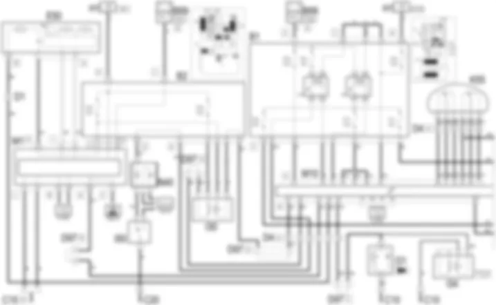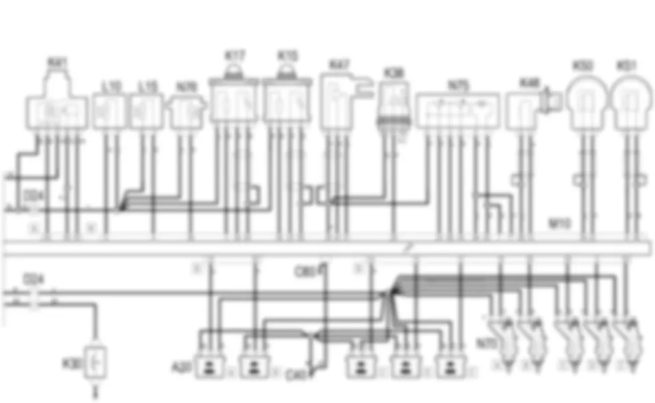

Wiring diagram - PETROL ENGINES ELECTRONIC MANAGEMENT - Fiat STILO 2.4 20v da 07/03 a 12/03
Components - PETROL ENGINES ELECTRONIC MANAGEMENT - Fiat STILO 2.4 20v da 07/03 a 12/03
| Component code | Description | Reference to the assembly |
| A30 | Ignition coil | |
| B2 | Junction unit under dashboard | |
| C10 | Left front earth | - |
| C15 | Driver''s dashboard earth | - |
| C20 | Passenger dashboard earth | - |
| C40 | Earth on engine | - |
| C60 | Injection control unit earth | - |
| D1 | Front/dashboard coupling | - |
| D1 | Front/dashboard coupling | - |
| D4 | Front/engine coupling | - |
| D4 | Front/engine coupling | - |
| D24 | Engine/i.e. coupling | - |
| D24 | Engine/i.e. coupling | - |
| D81 | Injector coupling | - |
| D81 | Injector coupling | - |
| D97 | Short circuit coupling | - |
| E50 | Instrument panel | |
| I30 | Brake pedal switch | - |
| I31 | Clutch pedal switch | - |
| I34 | Starting enablement switch on brake pedal | - |
| I50 | Inertia switch | |
| K16 | Lambda sensor on pre-catalyzer -2 | - |
| K17 | Lambda sensor downstream of the post-converter | |
| K36 | Engine temperature sending unit | |
| K43 | Integrated air temperature sensor | |
| K47 | Timing sensor | |
| L10 | Fuel vapour recovery solenoid valve | |
| M1 | Body computer | |
| N40 | Fuel level gauge | - |
| N70 | Injector | |
| N76 | Variable valve timing actuator |
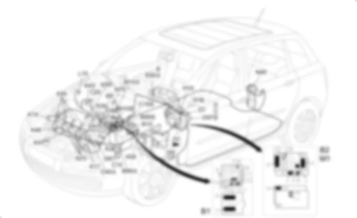
Component location - PETROL ENGINES ELECTRONIC MANAGEMENT - Fiat STILO 2.4 20v da 07/03 a 12/03
Components - PETROL ENGINES ELECTRONIC MANAGEMENT - Fiat STILO 2.4 20v da 07/03 a 12/03
| Component code | Description | Reference to the assembly |
| A30 | Ignition coil | |
| B2 | Junction unit under dashboard | |
| C10 | Left front earth | - |
| C15 | Driver''s dashboard earth | - |
| C20 | Passenger dashboard earth | - |
| C40 | Earth on engine | - |
| C60 | Injection control unit earth | - |
| D1 | Front/dashboard coupling | - |
| D1 | Front/dashboard coupling | - |
| D4 | Front/engine coupling | - |
| D4 | Front/engine coupling | - |
| D24 | Engine/i.e. coupling | - |
| D24 | Engine/i.e. coupling | - |
| D81 | Injector coupling | - |
| D81 | Injector coupling | - |
| D97 | Short circuit coupling | - |
| E50 | Instrument panel | |
| I30 | Brake pedal switch | - |
| I31 | Clutch pedal switch | - |
| I34 | Starting enablement switch on brake pedal | - |
| I50 | Inertia switch | |
| K16 | Lambda sensor on pre-catalyzer -2 | - |
| K17 | Lambda sensor downstream of the post-converter | |
| K36 | Engine temperature sending unit | |
| K43 | Integrated air temperature sensor | |
| K47 | Timing sensor | |
| L10 | Fuel vapour recovery solenoid valve | |
| M1 | Body computer | |
| N40 | Fuel level gauge | - |
| N70 | Injector | |
| N76 | Variable valve timing actuator |
Description - PETROL ENGINES ELECTRONIC MANAGEMENT - Fiat STILO 2.4 20v da 07/03 a 12/03
An electronic control system supervises and governs all engine parameters to optimise performance and fuel consumption by means of a real-time response to different service conditions.The system is managed by a single control unit which controls both ignition and injection.
Operational description - PETROL ENGINES ELECTRONIC MANAGEMENT - Fiat STILO 2.4 20v da 07/03 a 12/03
The engine management control unit M10 controls and governs the entire electronic ignition and injection system.The control unit M10 is supplied directly by the battery at pin 15 of connector A via a line protected by fuse F18 of the engine compartment junction unit B1The ignition-operated power supply (15/54) arrives via a line protected by fuse F16 of the engine compartment junction unit B1 at pin 47 of connector A of M10 .
 Deutsch
 English
 English
 Español
 Français
 Nederlands
 Русский


