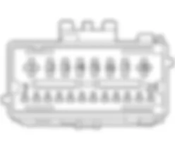
Components - CAN CONNECTION LINES - Fiat ULYSSE 2.2 16V JTD fino a 04/03
| Component code | Description | Reference to the assembly |
| A001 | BATTERY | |
| B001 | ENGINE COMPARTMENT JUNCTION UNIT | |
| C011 | RIGHT FRONT EARTH | - |
| D001 | FRONT/DASHBOARD COUPLING | - |
| D006 | FRONT/REAR COUPLING | - |
| D020 | DASHBOARD/REAR COUPLING | - |
| D030 | DRIVER''S FRONT DOOR COUPLING | - |
| D031 | PASSENGER FRONT DOOR COUPLING | - |
| D042 | COURTESY LIGHT COUPLING | - |
| D070 | DRIVER''S SEAT COUPLING | - |
| E050 | INSTRUMENT PANEL | |
| K125 | RAIN AND DUSK SENSOR | - |
| M001 | BODY COMPUTER | |
| M010 | ENGINE MANAGEMENT CONTROL UNIT | |
| M030 | ALARM CONTROL UNIT | - |
| M047 | TYRE INFLATION PRESSURE CONTROL UNIT | - |
| M050 | ABS CONTROL UNIT | |
| M055 | AUTOMATIC TRANSMISSION CONTROL UNIT | - |
| M060 | AIR BAG CONTROL UNIT | |
| M066 | DRIVER''S DOOR CONTROL UNIT (NPG) | |
| M067 | PASSENGER DOOR CONTROL UNIT (NPP) | - |
| M070 | CLIMATE CONTROL SYSTEM CONTROL UNIT | - |
| M076 | Seats/mirrors with memory control unit | - |
| M084 | PARKING SENSOR CONTROL UNIT | - |
| M091 | SLEWING CONTROL UNIT | - |
| M093 | STEERING WHEEL NODE CONTROL UNIT (NVO) | |
| M140 | WARNING LIGHTS AND MILOMETER CONTROL UNIT (NSO) | - |
| M160 | CONNECT CONTROL PANEL | - |
| M171 | SLIDING SIDE DOOR NODE | |
| M172 | MULTIFUNCTION SCREEN NODE | - |
| M180 | DIESEL ADDITIVE CONTROL UNIT | |
| M181 | Trailer control unit | - |
| N036 | FRONT SUN ROOF MOTOR | |
| N155 | CENTRE SUN ROOF MOTOR | |
| N156 | REAR SUN ROOF MOTOR | |
| P020 | RADIO | - |
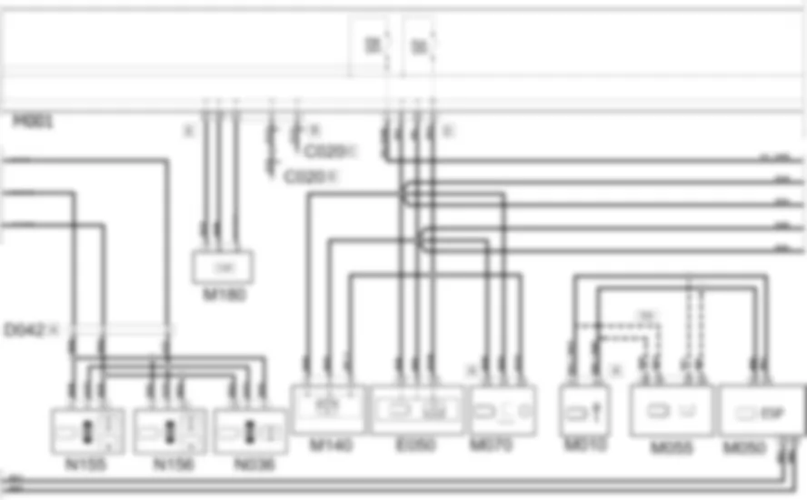
A CAN (Controller Area Network) architecture is used for the electrical connections present in the vehicle: the purpose of this hardware and software solution is to manage the resources present on the vehicle effectively and allow sharing of information between the various electronic devices, device integration through the use of a network, high speed information exchange, a reduction in the number of wires/connectors with the consequent financial benefits - and a higher standard of quality and reliability.Since the number of control units present on the vehicle is high, the amount of information managed is also high. This is why it is beneficial to use a CAN system.Signals are transmitted on CAN type serial Buses in which one cable is associated with a "high" voltage level (H) and athe other with a "low" voltage level (L): the value allocated to the transmitted bit is represented by the difference between the CAN-H and CAN-L voltage levels.The various electronic devices making up the system, referred to as network "Nodes", are connected to the CAN network via communication interfaces known as "transceivers" built into the devices.The exchange of information at CAN type serial lines is only possible using a transmission protocol which is the collection of rules that allow communication between two or more nodes.The main element of the CAN network is the Body Computer Node.The body computer Node is responsible for activating the network when the ignition key is turned ON.The body computer Node also performs the task of monitoring the network. In this way it is possible to check network activity status, the operational fault status of individual electronic devices (nodes) and any faults in the CAN network.The structure for this vehicle consists of three communication networks which connect nodes belonging to the different areas (vehicle dynamic control and bodywork functions) and a certain number of complementary serial lines used for diagnosis and other specific functions:a CAN for dynamic vehicle control (high speed),- a CAN network known as the CAN CONF network which connects the Body Computer to the information or comfort equipment.- a CAN network known as the CAN CAR network which connects the Body Computer to the safety devices or services.Fault diagnosis of the nodes connected to the CAN is carried out with the aid of the Body Computer node, whilst special K lines are used to diagnose the vehicle dynamic control network.Power is distributed via the junction units and/or fuse boxes to ensure maximum electrical protection and minimum wiring complexity.
The body computer node M001 supplies the various electronic control units connected to it via the CAN.Pins 1 and 2 of connector A of body computer node M001 are connected to pins 4 and 5 (respectively) of connector D of engine compartment junction unit B001, from which it takes power through fuses MF04 and MF05 (respectively).The cAN network is subdivided into CAN, CAN CONF, CAN CAR.The CAN CAR consists of the following components that are connected to body computer node M001:- steering wheel node control unit M093 (pins 5, 3, 1 connector A respectively) are connected to pin 11 connector B, 3 and 5 connector G;- air bag node control unit M060 (pins 37, 30, 33 respectively) are connected to pin 11 connector B, 23 and 21 connector L;- trailer control unit M181 (pins 1, 2, 4 connector B respectively) is connected to pins 37, 38 connector I and 4 connector F;- rain and dusk sensor K125 (pins 2, 4, 1 respectively) is connected to pins 26, 26 connector L and 3 connector H;- alarm control unit M030 (pins 10, 7, 12 connector A respectively) is connected to pins 4, 1 and 6 connector C;- diesel additive control unit M180 (pins 3, 6, 7 respectively) is connected to pin 12 connector B, 35 and 37 connector E;- engine compartment junction unit B001 (pins 12, 11 connector F respectively) is connected to pins 25 and 26 of connector E.The CAN CONF consists of the following components that are connected to body computer node M001:- air bag node control unit M067 (pins 19, 20, 1 respectively) are connected to pins 38, 40 connector L, 40 and 9 connector F;- air bag node control unit M066 (pins 1, 20, 19 respectively) are connected to pins 9 connector F, 36 and 38 connector I;- Seat/mirror with memory control unit M076 (pins A7, A5, C5 connector A respectively) is connected to pin 3 connector F, 36 and 38 connector I;- parking sensor control unit M084 (pins 5, 14, 10 connector A respectively) is connected to pins 36, 38 connector I and 11 connector F, but only one line is protected by fuse F12 (pin 11 connector F);- sliding side door control unit M171 (pins 5, 4, 12 connector A respectively) is connected to pins 36, 38 connector I and 8 connector H, but only one line is protected by fuse F08 (pin 8 connector H);- front sunroof motor N036, central sunroof motor N155 and rear sunroof motor N156 (pins 4, 10, 5 respectively) are connected to pins 36, 38 connector I and 3 connector H, but only one line is protected by fuse F05 (pin 3 connector H);- instrument panel E050 (pins 12, 6, 13 respectively), warning light and odometer control unit M140 (pins 5, 2, 4 respectively) and climate control system control unit M070 (pins 15, 14, 10 respectively) are connected to pins 8, 10 and 6 of connector D but only one line is protected by fuse F14 (pin 6 connector D);- multifunction screen node M172 (pins 9, 7, 1 respectively) and radio P020 (pins 10, 13, 12 connector A respectively) are connected to pins 8, 10 and 1 of connector D, but only one line is protected by fuse F08 (pin 1 connector D).The latter connections may vary according to the vehicle specification. Connect Nav or Nav+ P020 (pins 10, 13, 12 connector D respectively) are connected to pins 8, 10 and 1 of connector D and the following are also connected:- Connect M160 (pins 1, 2, 4 respectively) to pins 12, 11 and 6 of connector B;- Multifunction screen node M172 (pins 6, 4 respectively) to pins 5 and 12 of connector A.The CAN network (dynamic control network) is also made up of the following components that connect to pins 4, 2 of connector E of body computer M001:- steering wheel node control unit M093 (pins 1, 2 connector D respectively);- yaw sensor M091 (pins 2, 3 respectively);- tyre pressure check control unit M047 (pins 9, 18 respectively);- the ABS/ESP control unit M050 (pins 25, 45 respectively).Automatic transmission control unit M055 (pins 29, 30 respectively) is still connected, if an automtic transmission control unit is fitted, to ABS/ESP control unit M050 (pins 14, 35) to which is connected (pins 38, 39) engine control unit M010 (pins A3, A4 connector A respectively). If a manual gearbox is fitted, engine control unit M010 (pins A3, A4 connector A respectively) is connected directly.


