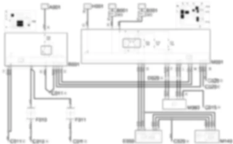
Wiring Diagram - FOG LIGHTS - Fiat ULYSSE 2.2 16V JTD fino a 04/03
Components - FOG LIGHTS - Fiat ULYSSE 2.2 16V JTD fino a 04/03
| Component code | Description | Reference to the assembly |
| B001 | Engine compartment junction unit | 5,505A |
| C010 | Left front earth | - |
| C011 | Right front earth | - |
| C015 | Driver''s dashboard earth | - |
| C020 | Passenger dashboard earth | - |
| D020 | Dashboard/rear coupling | - |
| E050 | Instrument panel | 5560B |
| F010 | Left headlamp | 5540B |
| F011 | Right headlamp | 5540B |
| M001 | Body computer | 5505A |
| M093 | Steering wheel node control unit (NVO) | 5550A |
| M140 | Warning lights and milometer control unit (NSO) | - |
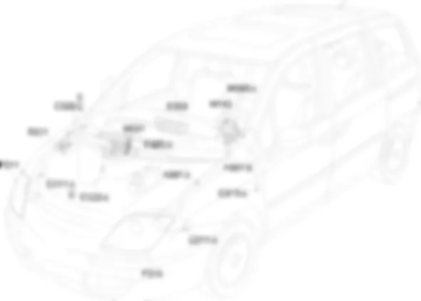
Location Components - FOG LIGHTS - Fiat ULYSSE 2.2 16V JTD fino a 04/03
Components - FOG LIGHTS - Fiat ULYSSE 2.2 16V JTD fino a 04/03
| Component code | Description | Reference to the assembly |
| B001 | Engine compartment junction unit | 5,505A |
| C010 | Left front earth | - |
| C011 | Right front earth | - |
| C015 | Driver''s dashboard earth | - |
| C020 | Passenger dashboard earth | - |
| D020 | Dashboard/rear coupling | - |
| E050 | Instrument panel | 5560B |
| F010 | Left headlamp | 5540B |
| F011 | Right headlamp | 5540B |
| M001 | Body computer | 5505A |
| M093 | Steering wheel node control unit (NVO) | 5550A |
| M140 | Warning lights and milometer control unit (NSO) | - |
Description - FOG LIGHTS - Fiat ULYSSE 2.2 16V JTD fino a 04/03
The vehicle is equipped with two additional fog lights, located in the light clusters.The fog lights are activated via the special ring nut control on the stalk unit (steering wheel node); when the lights are on, the warning light in the instrument panel comes on.A relay located in the engine bay control unit controls fog lamp activation via a line protected by a fuse.The relay is managed by the Body Computer relay excitation is activated with:
Operational Description - FOG LIGHTS - Fiat ULYSSE 2.2 16V JTD fino a 04/03
The command to switch on the fog lights is supplied by the steering wheel node control unit M093 to the body computer node M001. The signal travels via the CAN which connects the two control units.The steering wheel node control unit M093 receives a supply (pin 5 connector A) through the line protected by fuse F11, located in the body computer node M001; it receives a supply via the CAN (pin 6 connector A) from the line protected by fuse F16, located in the body computer node M001.The engine compartment junction unit B001 receives the request, via the CAN, to switch on the fog lights and energizes the internal relay, supplying the fog light bulbs (pin 10 connector F) located inside the left front light cluster F010 and the right front light cluster F011. The power supply is direct from the battery and is protected by fuse F06 housed inside the engine compartment junction unit B001.The warning light is switched on by the milometer warning lights node M140 which communicates with the instrument panel E050 and the body computer node M001 via the CAN.The instrument panel E050 and the milometer warning lights node M140 receive a supply via the CAN (pin 13 of E50 and pin 4 of M140) through the line protected by fuse F24 of the body computer M001.

