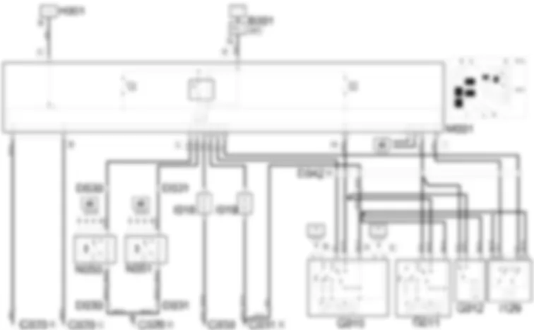
Wiring Diagram - COURTESY LIGHTS - Fiat ULYSSE 2.2 16V JTD fino a 04/03
Components - COURTESY LIGHTS - Fiat ULYSSE 2.2 16V JTD fino a 04/03
| Component code | Description | Reference to the assembly |
| C020 | Passenger dashboard earth | - |
| C030 | Left rear earth | - |
| C031 | Right rear earth | - |
| D030 | Left front door coupling | - |
| D031 | Right front door coupling | - |
| D042 | Courtesy light coupling | - |
| G010 | Front courtesy light | 7040E |
| G011 | Passenger area front courtesy light | 7040E |
| G012 | Passenger area rear courtesy light | 7040E |
| I018 | Switch on left rear door | - |
| I019 | Switch on right rear door | - |
| I129 | Courtesy lights disabling switch | - |
| M001 | Body computer | 5505A |
| N050 | Left front door lock geared motor | 7005N |
| N051 | Right front door lock geared motor | 7005N |
Location Components - COURTESY LIGHTS - Fiat ULYSSE 2.2 16V JTD fino a 04/03
Components - COURTESY LIGHTS - Fiat ULYSSE 2.2 16V JTD fino a 04/03
| Component code | Description | Reference to the assembly |
| C020 | Passenger dashboard earth | - |
| C030 | Left rear earth | - |
| C031 | Right rear earth | - |
| D030 | Left front door coupling | - |
| D031 | Right front door coupling | - |
| D042 | Courtesy light coupling | - |
| G010 | Front courtesy light | 7040E |
| G011 | Passenger area front courtesy light | 7040E |
| G012 | Passenger area rear courtesy light | 7040E |
| I018 | Switch on left rear door | - |
| I019 | Switch on right rear door | - |
| I129 | Courtesy lights disabling switch | - |
| M001 | Body computer | 5505A |
| N050 | Left front door lock geared motor | 7005N |
| N051 | Right front door lock geared motor | 7005N |
Description - COURTESY LIGHTS - Fiat ULYSSE 2.2 16V JTD fino a 04/03
The front courtesy light and the centre courtesy light have three lamps with three control switches:
Operational Description - COURTESY LIGHTS - Fiat ULYSSE 2.2 16V JTD fino a 04/03
The courtesy lights in the passenger compartment come on in "courtesy light" mode dependent on the opening of the door.The opening of the front doors is signalled via the switch incorporated in the locks N050 and N051.When the door is opened, the (normally closed type) switch provides an earth signal at pin 4 (left front door) and pin 5 (right front door) for connector L of the body computer node M001.Having received the signal, the body computer node M001, sends the command, from pin 32 connector L, to the front courtesy light G010, with a supply coming from the line protected by fuse F12 of M001.Having received the signal, the body computer node M001, sends the command, from pin 32 connector L, to the front courtesy light G010, with a supply coming from the line protected by fuse F12 of M001.The opening of the sliding side doors is signalled by specific switches I018 (left sliding side door) and I019 (right sliding side door).When the sliding side door is open, an earth signal reaches the body computer node M001 at pins 34 (left sliding side door) and 33 (right sliding side door) of connector L. The body computer node M001 sends a command, from pin 6 connector I, to the courtesy lights G011 and G012 providing a power supply for the bulbs contained inside.The front courtesy light mode can be disabled/enabled via switch I129. The enabling command is given by supplying an earth signal from pin B2 of I129 to pin 25 of connector L of M001; whilst the disabling command is given by supplying the same earth signal from pin A2 of I129 to pin 15 connector I of M001.For operation in manual mode, the body computer node M001 provides a supply, from pin 12 of connector H, coming from the line protected by fuse F07 of M001, directly to the front courtesy light G010 and to the rear courtesy lights G011 and G012.It is possisble to switch on the bulbs manually using the switches inside the courtesy lights G010, G011 and G012.

