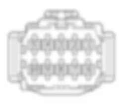
Wiring Diagram - HORNS - Fiat ULYSSE 2.2 16V JTD fino a 04/03
Components - HORNS - Fiat ULYSSE 2.2 16V JTD fino a 04/03
| Component code | Description | Reference to the assembly |
| B001 | Engine compartment junction unit | 5505A |
| C011 | Right front earth | - |
| C015 | Driver''s dashboard earth | - |
| C020 | Passenger dashboard earth | - |
| D020 | Dashboard/rear coupling | - |
| M001 | Body computer | 5505A |
| M093 | Steering wheel node control unit (NVO) | 5550A |
| P005 | Single tone horn | 5550B |
Location Components - HORNS - Fiat ULYSSE 2.2 16V JTD fino a 04/03
Components - HORNS - Fiat ULYSSE 2.2 16V JTD fino a 04/03
| Component code | Description | Reference to the assembly |
| B001 | Engine compartment junction unit | 5505A |
| C011 | Right front earth | - |
| C015 | Driver''s dashboard earth | - |
| C020 | Passenger dashboard earth | - |
| D020 | Dashboard/rear coupling | - |
| M001 | Body computer | 5505A |
| M093 | Steering wheel node control unit (NVO) | 5550A |
| P005 | Single tone horn | 5550B |
Description - HORNS - Fiat ULYSSE 2.2 16V JTD fino a 04/03
The vehicle is equipped with a horn system consisting of two horns with different tones: one high tone and one low tone: the two horns come on simultaneously.The horns are operated by pressing the sides of the steering wheel cover (around the Air Bag).The horn circuit is protected by a specific fuse and controlled by a relay located in the engine compartment junction unit.For safety reasons, the horns can be operated at any time even with the key in position S (or switched off).
Operational Description - HORNS - Fiat ULYSSE 2.2 16V JTD fino a 04/03
The command for the horns is supplied by the steering wheel node control unit M093 to the body computer node M001. The signal travels via the CAN which connects the two control units.The steering wheel node control unit M093 receives a supply (pin 5 connector A) through the line protected by fuse F11, located in the body computer node M001; it receives a supply via the CAN (pin 6 connector A) from the line protected by fuse F16, located in the body computer node M001.The signal is sent, via the CAN, to the engine compartment junction unit which supplies the horns P005 (pin 7 connector H of B001) via the line protected by fuse F13. The supply line is managed by a specific relay, located in the engine compartment junction unit B001.


