Components - HEADLAMP WASHER - Fiat ULYSSE 2.2 16V JTD fino a 04/03
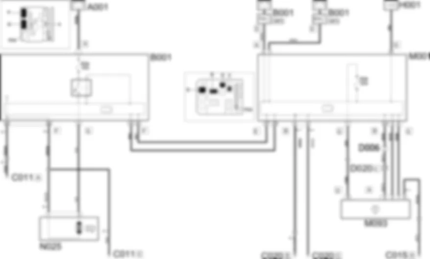
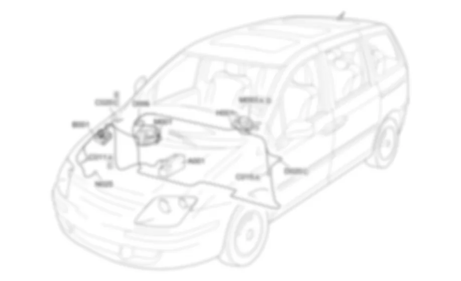
| Component code | Description | Reference to the assembly |
| A001 | BATTERY | - |
| B001 | ENGINE COMPARTMENT JUNCTION UNIT | |
| C011 | RIGHT FRONT EARTH | - |
| C015 | DRIVER''S DASHBOARD EARTH | - |
| C020 | PASSENGER SIDE DASHBOARD EARTH | - |
| D006 | FRONT/REAR COUPLING | - |
| D020 | DASHBOARD/REAR COUPLING | - |
| H001 | Ignition switch | |
| M001 | BODY COMPUTER | |
| M093 | STEERING WHEEL NODE CONTROL UNIT (NVO) | |
| N025 | HEADLAMP WASHER PUMP MOTOR |
The headlamp washer cleans the headlamp lenses as the windscreen is being cleaned.The headlamp washer function is managed by the Body Computer which automatically activates the headlamp washer, with the dipped or main beam headlamps on, when the windscreen washers are activated through the lever on the right of the steering wheel.The headlamp washer consists of a pump that sends detergent to a nozzle located in the bumpers. This in turn sprays a powerful jet on the headlamp.A timer activates the headlamp washer pump by means of a series of pulses lasting about half a second.
The headlamp washer function is switched on by activating the windscreen wipers with the dipped headlamps on.The steering wheel node control unit M093 receives a power supply (pin 5 connector A and pin 4 connector D) from the Body computer node M001 (pin 11 connector B and pin 1 connector G respectively) via two lines of which only the second is protected by fuse F04.The command for switching on the headlamp washer function is supplied from the steering wheel node control unit M093 (pins 1 and 3 of connector A) to the Body computer node M001 (pins 5 and 3 of connector G respectively). The signal always travels via the CAN line.The Body computer node M001, in turn, transmits the signal (pins 25 and 27 of connector E), via the CAN line, to the engine compartment junction unit B001 (pins 12 and 11 respectively of connector F).The headlamp electric pump motor N025 (pin 2) is supplied by means of pin 1 of connector G of the engine compartment junction unit B001 via a line protected by fuse F04.In addition to being protected by a specific fuse, the power supply provided is operated by a special relay also housed in the engine compartment junction unit B001.

