Components - HEADLAMP AGLINMENT CORRECTOR - Fiat ULYSSE 2.2 16V JTD fino a 04/03
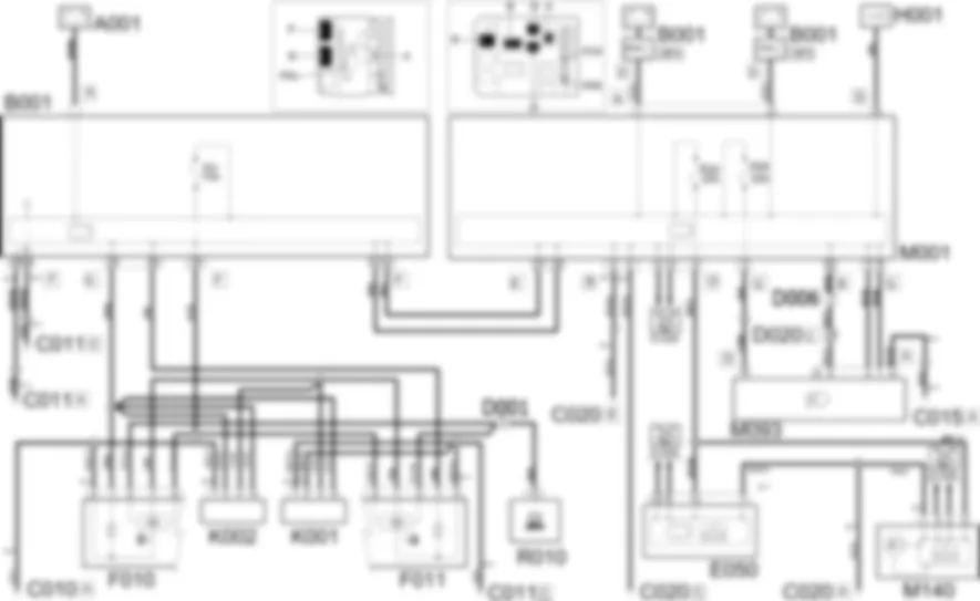
| Component code | Description | Reference to the assembly |
| A001 | BATTERY | - |
| B001 | ENGINE COMPARTMENT JUNCTION UNIT | |
| C010 | LEFT FRONT EARTH | - |
| C011 | RIGHT FRONT EARTH | - |
| C015 | DRIVER''S DASHBOARD EARTH | - |
| C020 | PASSENGER SIDE DASHBOARD EARTH | - |
| D001 | FRONT/DASHBOARD COUPLING | - |
| D006 | FRONT/REAR COUPLING | - |
| D020 | DASHBOARD/REAR COUPLING | - |
| E050 | INSTRUMENT PANEL | |
| F010 | LEFT HEADLAMP | |
| F011 | RIGHT HEADLAMP | |
| H001 | Ignition switch | - |
| K001 | HEADLAMP ALIGNMENT CORRECTOR FRONT POTENTIOMETER (CAF) | - |
| K002 | HEADLAMP ALIGNMENT CORRECTOR REAR POTENTIOMETER (CAF) | - |
| M001 | BODY COMPUTER | |
| M093 | STEERING WHEEL NODE CONTROL UNIT (NVO) | |
| M140 | WARNING LIGHTS AND MILOMETER CONTROL UNIT (NSO) | - |
| R010 | MULTIPLE DIAGNOSTIC COUPLING | - |
The vehicle is fitted with two GAS DISCHARGE headlamps.The function in question is managed by an electronic device inside the two headlamps by means of two sensor (potentiometer) signals, located on the wheel axles that measure the front and rear geometry.Depending on the inputs, the control unit controls the relevant adjustment motor, located in the headlamps, directly and tilts it as appropriate.The device is enabled only with the dipped beams on.The device which controls the engagement of the dipped headlamps also supplies the geometry sensors, whilst the electronics for the two headlamps is supplied by a line protected by a specific fuse.768
The automatic headlamp adjustment system is only supplied with the dipped headlamps on.The sensors K001 (pin 5) and K002 (pins 2 and 5) that control the vehicle geometry receive a power supply from the engine compartment junction unit B001 (pin 25 connector G).Pin 1 of K002 and pins 1 and 2 of K001 are earthed.Sensors K001 and K002 provide the electronics incorporated in the headlamps F010 and F011 (pin 7) with information concerning the vehicle geometry from pin 4. The electric motors automatically correct the light beam according to the information received.The electronics are also supplied at pin 9 of F010 and F011 by the engine compartment junction unit B001 (pin 20 connector C) from the line protected by fuse F01 of the junction unit.The self-diagnostic data for the two control units can be read by connecting to the multiple diagnostic coupling R010 (pin 13): it receives the signals from pin 5 of F010 and F011.

