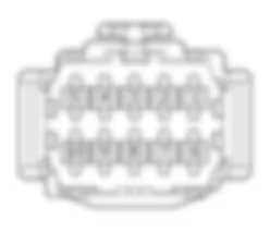
Wiring Diagram - SLIDING SIDE DOORS - Fiat ULYSSE 2.2 16V JTD fino a 04/03
Components - SLIDING SIDE DOORS - Fiat ULYSSE 2.2 16V JTD fino a 04/03
| Component code | Description | Reference to the assembly |
| C015 | Driver''s dashboard earth | - |
| C030 | Left rear earth | - |
| C031 | Right rear earth | - |
| D020 | Dashboard/rear coupling | - |
| D042 | Courtesy light coupling | - |
| I131 | Left sliding side door closing end of travel switch | - |
| I132 | Right sliding side door closing end of travel switch | - |
| I133 | Left sliding side door opening switch on courtesy light | 7020N |
| I134 | Right sliding side door opening switch on courtesy light | 7020N |
| I135 | Left sliding side door opening switch on left centre pillar | - |
| I136 | Right sliding side door opening switch on right centre pillar | - |
| I137 | Left sliding side door lock switch | - |
| I138 | Right sliding side door lock switch | - |
| M001 | Body computer | 5505A |
| M093 | Steering wheel node control unit (NVO) | 5550A |
| M171 | Sliding side door node | 5505A |
| N166 | Left sliding side door lock geared motor | 7020N |
| N167 | Right sliding side door lock geared motor | 7020N |
| N168 | Left sliding side door electric motor | 7020N |
| N169 | Right sliding side door electric motor | 7020N |
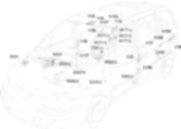
Location Components - SLIDING SIDE DOORS - Fiat ULYSSE 2.2 16V JTD fino a 04/03
Components - SLIDING SIDE DOORS - Fiat ULYSSE 2.2 16V JTD fino a 04/03
| Component code | Description | Reference to the assembly |
| C015 | Driver''s dashboard earth | - |
| C030 | Left rear earth | - |
| C031 | Right rear earth | - |
| D020 | Dashboard/rear coupling | - |
| D042 | Courtesy light coupling | - |
| I131 | Left sliding side door closing end of travel switch | - |
| I132 | Right sliding side door closing end of travel switch | - |
| I133 | Left sliding side door opening switch on courtesy light | 7020N |
| I134 | Right sliding side door opening switch on courtesy light | 7020N |
| I135 | Left sliding side door opening switch on left centre pillar | - |
| I136 | Right sliding side door opening switch on right centre pillar | - |
| I137 | Left sliding side door lock switch | - |
| I138 | Right sliding side door lock switch | - |
| M001 | Body computer | 5505A |
| M093 | Steering wheel node control unit (NVO) | 5550A |
| M171 | Sliding side door node | 5505A |
| N166 | Left sliding side door lock geared motor | 7020N |
| N167 | Right sliding side door lock geared motor | 7020N |
| N168 | Left sliding side door electric motor | 7020N |
| N169 | Right sliding side door electric motor | 7020N |
Description - SLIDING SIDE DOORS - Fiat ULYSSE 2.2 16V JTD fino a 04/03
The two sliding side doors can be opened/closed electrically from the inside:
Operational Description - SLIDING SIDE DOORS - Fiat ULYSSE 2.2 16V JTD fino a 04/03
The steering wheel node M093 receives the door open/closed signal from the remote control.The command (door opening or closing) is provided by the steering wheel node control unit M093 to the body computer node M001. The signal travels via the CAN which connects the two control units.The steering wheel node control unit M093 receives a supply (pin 5 connector A) through the line protected by fuse F11, located in the body computer node M001; it receives a supply via the CAN (pin 6 connector A) from the line protected by fuse F16, located in the body computer node M001.The signal reaches the steering wheel node control unit M093 and is sent, via the CAN, to the sliding side door node M171, connected to the network via pins 11, 13 connector A.The sliding side door node M171 receives a supply, via the CAN (pin 4 connector A) from the line protected by fuse F01 for the body computer node M001.Pins 1, 8 connector A receive a direct supply via the line protected by fuses F01 and F02 of the maxifuse box B005; the control unit is earthed at pins 9, 16.The command for the electrical opening of the sliding side doors comes from the specific switches fitted in the courtesy light I133 (left side) and I134 (right side) or from the switches on the centre pillars I135 (left side) and I136 (right side).All the switches receive a supply, at pin 4, via the CAN, from the line protected by fuse F01 of the body computer node M001.The switches are earthed at pin 3, whilst an earth signal is sent from pin 6 to control unit M171, to pins 2, 15, 3 and 6, connector A, respectively to control the opening of the specific sliding side door.The control unit M171 controls the electric motors for the locks N166 left and N167 right from pins 5, 14 of connector A.The control unit receives the signal, at pins 10, 7, that the locks are correctly locked from the door switches I137 and I138, respectively.The electric motors for moving the sliding side doors N168 and N169 are controlled by pins 1, 2 connector B and pins 1, 2 connector E, respectively.Switches I131 and I132 notify the control unit that the sliding side doors are correctly closed.Switch I131 is connected to connector C of control unit M171 and switch I132 is connected to connector D of the control unit. The control unit provides the switches with a supply from pins 3, 4 of connector C and D for the warning light incorporated in the actual switches.


