Wiring Diagram - INSTRUMENT PANEL - Fiat ULYSSE 2.2 16V JTD fino a 04/03
Components - INSTRUMENT PANEL - Fiat ULYSSE 2.2 16V JTD fino a 04/03
| Component code | Description | Reference to the assembly |
| B001 | Engine compartment junction unit | 5505A |
| C010 | Left front earth | - |
| C011 | Right front earth | - |
| C020 | Passenger dashboard earth | - |
| D001 | Front/dashboard coupling | - |
| D070 | Driver''s seat coupling | - |
| D213 | Fuel tank coupling | - |
| E050 | Instrument panel | 5560B |
| I040 | Handbrake applied switch | 5550D |
| I046 | Driver''s seat belt switch | - |
| K020 | Left brake pad wear sensor (switch) | 3310A |
| K021 | Right brake pad wear sensor (switch) | 3310A |
| K025 | Brake fluid level sensor (switch) | - |
| K026 | Engine coolant level sensor | - |
| K030 | Engine oil pressure switch | 1084A |
| K032 | Engine oil level sensor | 1084A |
| K036 | Engine coolant temperature sensor/sender unit | 1056B |
| M001 | Body computer | 5505A |
| M010 | Engine management control unit | 1060G |
| M060 | Air Bag control unit | 5580C |
| M140 | Warning lights and milometer control unit (NSO) | - |
| M172 | Multifunction screen node | - |
| N040 | Fuel pump | 1040A |
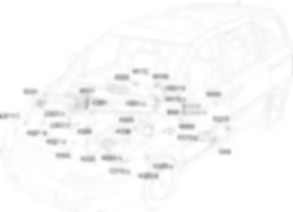
Location Components - INSTRUMENT PANEL - Fiat ULYSSE 2.2 16V JTD fino a 04/03
Components - INSTRUMENT PANEL - Fiat ULYSSE 2.2 16V JTD fino a 04/03
| Component code | Description | Reference to the assembly |
| B001 | Engine compartment junction unit | 5505A |
| C010 | Left front earth | - |
| C011 | Right front earth | - |
| C020 | Passenger dashboard earth | - |
| D001 | Front/dashboard coupling | - |
| D070 | Driver''s seat coupling | - |
| D213 | Fuel tank coupling | - |
| E050 | Instrument panel | 5560B |
| I040 | Handbrake applied switch | 5550D |
| I046 | Driver''s seat belt switch | - |
| K020 | Left brake pad wear sensor (switch) | 3310A |
| K021 | Right brake pad wear sensor (switch) | 3310A |
| K025 | Brake fluid level sensor (switch) | - |
| K026 | Engine coolant level sensor | - |
| K030 | Engine oil pressure switch | 1084A |
| K032 | Engine oil level sensor | 1084A |
| K036 | Engine coolant temperature sensor/sender unit | 1056B |
| M001 | Body computer | 5505A |
| M010 | Engine management control unit | 1060G |
| M060 | Air Bag control unit | 5580C |
| M140 | Warning lights and milometer control unit (NSO) | - |
| M172 | Multifunction screen node | - |
| N040 | Fuel pump | 1040A |
Description - INSTRUMENT PANEL - Fiat ULYSSE 2.2 16V JTD fino a 04/03
The information for the driver is displayed by means of three elements:
Operational Description - INSTRUMENT PANEL - Fiat ULYSSE 2.2 16V JTD fino a 04/03
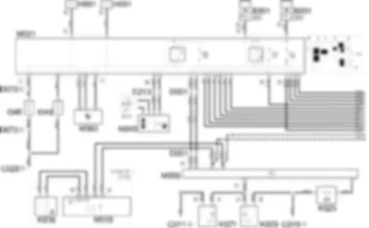
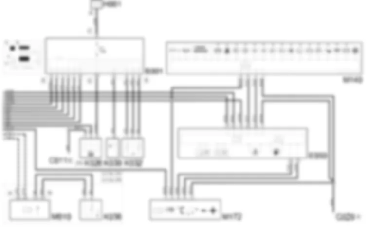
The management of the warning lights and the information shown by the display is entrusted to the milometer warning lights node M140, the instrument panel node E050 and the multifunction screen node M172 which receive information from the control units involved via the CAN.The three modules receive a supply via the CAN (pin 13 of E50, pin 4 of M140, pin 2 of M172) from the line protected by fuse F24 of the body computer M001.The milometer warning lights node M140 communicates, from pins 2, 5, via the CAN, with the instrument panel node E050, pins 16, 22; the instrument panel node E050 communicates, via the CAN, with the body computer node M001, at pins 10, 8 connector D. Pin 1 of M140 and pin 7 of E050 are earthed.The multifunction screen M172 receives a supply, at pin 1, from the body computer node M001 (pin 1 connector D) from the line protected by fuse F11. It communicates, from pins 4, 6, via the CAN, with the instrument panel node E050, at pins 24, 18. Pin 3 is connected to earth.The body computer node M001 communicates, from pin 4 connector F and from pins 30, 28 connector L, via the CAN, with the Air Bag control unit M060 at pins 47, 30, 33.Pin 37, connector L receives the signal coming from the driver''s seat belt switch I046 whilst pin 35 of the same connector receives the signal coming from the handbrake applied switch I040.The body computer node M001 receives information, from pins 15, 16 connector M, concerning the fuel level provided by the pump N040. Pins 13, 14, 29 connector M receive information from the engine oil level and temperature sensor K032; this information passes throught the engine compartment junction unit B001, entering at pins 4, 5, 6 connector B and exiting at pins 3, 4, 10 connector E.The engine compartment junction unit B001 receives information, at pin 11 connector B, concerning the engine oil pressure, coming from sensor K030, information transmitted to the body computer node M001 via the CAN.The body computer node M001 communicates, from pins 6, 8 connector M, via the CAN, with the engine compartment junction unit B001, at pins 1 5, connector E. The body computer node M001 also provides a supply, from pin 3 connector D, to the engine compartment junction unit B001, at pin 9 connector E through the line protected by fuse F11.The engine coolant level sensor K026, supplied by the engine compartment junction unit B001, through the line protected by fuse F01, provides a signal to the body computer node M001, pin 1 of connector M.The body computer node M001, communicates, from pins 2, 4 connector M, via the CAN, with the ABS control unit M050, at pins 24, 40 and with the engine management control unit M010, pins A4, A3 connector A.Engine management control unit M010 communicates information on coolant temperature supplied by sensor K036.ABS control unit M050 sends information on brake pad wear supplied by sensors K020 and K021 to pin 32, and brake fluid level, supplied by sensor K025 to pin 22.

