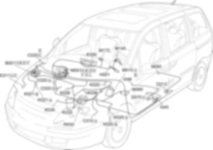
Components - INSTRUMENT PANEL - Fiat ULYSSE 2.2 16V JTD fino a 04/03
| Component code | Description | Reference to the assembly |
| B001 | ENGINE COMPARTMENT JUNCTION UNIT | |
| C010 | LEFT FRONT EARTH | - |
| C011 | RIGHT FRONT EARTH | - |
| C020 | PASSENGER SIDE DASHBOARD EARTH | - |
| D070 | DRIVER''S SEAT COUPLING | - |
| D213 | FUEL TANK COUPLING | - |
| E050 | INSTRUMENT PANEL | |
| H001 | Ignition switch | |
| I040 | HANDBRAKE APPLIED SWITCH | |
| I046 | DRIVER''S SEAT BELT SWITCH | - |
| K020 | LEFT BRAKE PAD WEAR SENSOR (SWITCH) | |
| K021 | RIGHT BRAKE PAD WEAR SENSOR (SWITCH) | |
| K025 | BRAKE FLUID LEVEL SENSOR (SWITCH) | - |
| K026 | Engine coolant level sensor | - |
| K030 | INSUFFICIENT ENGINE OIL PRESSURE SENSOR | |
| K032 | ENGINE OIL LEVEL SENSOR | |
| K036 | ENGINE COOLANT TEMPERATURE SENSOR/SENDER UNIT | |
| M001 | BODY COMPUTER | |
| M010 | ENGINE MANAGEMENT CONTROL UNIT | |
| M050 | ABS CONTROL UNIT | |
| M060 | AIR BAG CONTROL UNIT | |
| M140 | WARNING LIGHTS AND MILOMETER CONTROL UNIT (NSO) | - |
| M172 | MULTIFUNCTION SCREEN NODE | - |
| N040 | FUEL PUMP AND LEVEL GAUGE |
The information for the driver is displayed by means of three devices:- Instrument Panel Node in the centre of the dashboard;- Milometer Warning Lights Node located above the steering column;-Multifunction Screen Node fitted in front of the instrument panel on the standard version or built into it (DT colour screen) on the Connect Nav + versions.The Instrument Panel Node displays the following information:- speedometer;- rev counter;- Fuel level gauge;- Coolant temperature gauge;- odometer;- Minimum fuel level warning light;- Coolant overheating warning light;- Oil level gauge.The odometer can only be zeroed fully if the number indicated is less than 250.This zeroing can only be done once.The Milometer Warning lights Node is connected to the CAN and managed by the body computer node.The node is ruled by the instrument panel from which it receives display commands and to which it signals its status via the CAN.Milometer node warning lights:- Dipped headlamps warning light;- Main headlamps warning light;- Direction indicator warning lights;- Rear fog lamps warning light;- Fog lights warning light;- ESP warning light;- ABS warning light;- EOBD warning light;- Cruise Control warning light;- Brake fluid level and parking brake - EBD warning light;- Minimum oil pressure warning light;- Battery recharging warning light;- Diesel heater plugs warning light;- Driver''s seat belt warning light;- Passenger Air Bag disabled warning light;- Airbag warning light.The milometer display is capable of showing the following:- on the top line, the trip mileage and the engine oil level gauge (where fitted);- on the bottom line, the total mileage and service indicator.In addition, on versions equipped with automatic transmission, the gear engaged is displayed and there is a symbol warning of the presence of ice on the road.- time;- date;- outside temperature;- radio information (and CD changer);- on board computer (fuel consumption/average speed/range);- status of the doors.The lighting for the three modules can be dimmed: the intensity of the lighting is altered by means of a button located in the Milometer Warning Lights Node and is managed by the latter which then controls the Instrument Panel Node and the Multifunction Screen Node.All the details on the specifications and the operation of the instruments is contained in the "OWNER''S HANDBOOK".The operation of the warning lights which do not come under any other functions is illustrated below:- electronic speedometer;- electronic rev counter;- milometer/trip meter;- fuel level gauge with reserve warning light;- engine coolant temperature gauge with overheating warning light;- brake fluid level/handbrake applied - EBD warning light;- minimum engine oil pressure warning light.the other warning lights and displays are described and illustrated in the diagrams for the components to which they refer.
The management of the warning lights and the information shown by the display is entrusted to the milometer warning lights node M140 and to the instrument panel node E050 which receive information from the control units involved via the CAN.As well as these two nodes the multifunction screen node M172 incorporated in the DT colour screen is also included.Control units E050 (pin 13) and M140 (pin 4) receive power from body computer node M001 (pin 6 connector D) with one line protected by fuse F14.Odometer warning light node M140 (pins 2,5), instrument panel E050 (pins 6, 12) and body computer node M001 (pin 8, 10 connector D) communicate via the CAN network.Body computer node M001 (pins 21, 23 connector L) communicate with airbag control unit M060 (pins 33, 30 respectively), they also (pin 5 connector F) supply it with power (pin 47).The following are also connected to body computer node M001:- handbrake engaged switch I040 (pin 2) to pin 35 of connector L;- driver side seatbelt switch I046 (pin 2) to pin 37 of connector L;- fuel pump and level gauge N040 (pins 5 and 6 respectively) to pins 14 and 15 of connector E;- engine coolant level sensor K026 (pin 2) to pin 14 of connector G;- multifunction screen node M172 (pin 1) to pin 1 of connector D;- the multiple diagnostic connector system to pins 8 and 10 of connector G.Pins 3 and 4 of the electric fuel pump and level gauge N040 are connected to the electronic ignition and injection system.Pin 3 of coolant level sensor K026 is connectedto engine compartment junction unit B001 (pin 20 connector F) via a line protected by fuse F06.The following are also connected to engine compartment junction unit B001:- low engine oil pressure sensor K030 (pin 2) to pin 20 of connector B;- engine oil level sensor K032 (pins 1, 2, 3 respectively) to pins 7, 22, 6 of connector B.The information received from B001 is sent (pins 11, 12 connector F) to body computer node M001 (pins 2, 4 connector E) via the CAN network.Body computer M001 (pins 25, 27 connector E) communicates via the CAN network with ABS control unit M050 (pins 15, 26), which in turn communicates (pin 14, 25) with engine control unit M010 (pins A3, A4 connector A).In versions with an ESP device, control unitM050 communicates with engine control unit M010 via pins14 and 35.Engine coolant temperature K036 (pins 2, 1 respectively) is connected to engine control unit M010 (pins D1, E1 connector B).The following are supplied to ABS/ESP control unit M050:- pad wear sensors for left brake K020 and right brake K021 (pin 1 connector A) at pin 22;- signal for brake fluid sensor K025 (pin 1) at pin 21 (or pin 17 in versions with ESP).Multifunction screen node M172 (pins 7, 9) communicates with instrument panel E050 (pins 6, 12) via the CAN line.


