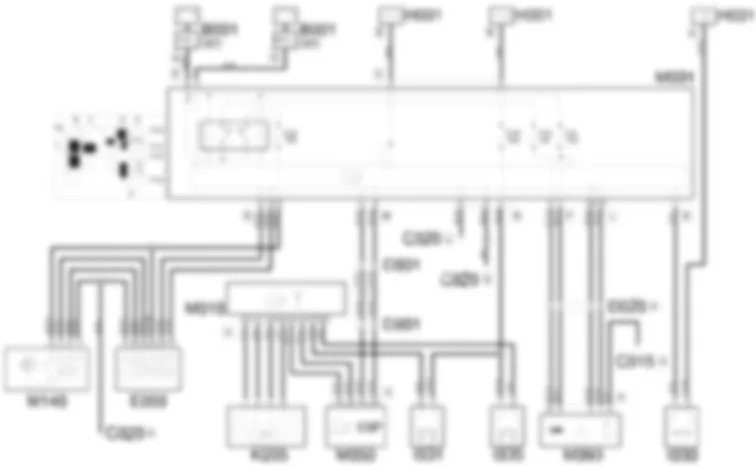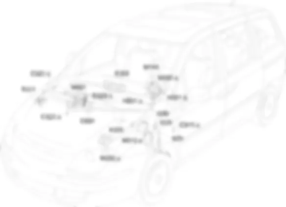
Wiring Diagram - CRUISE CONTROL - Fiat ULYSSE 2.2 16V JTD fino a 04/03
Components - CRUISE CONTROL - Fiat ULYSSE 2.2 16V JTD fino a 04/03
| Component code | Description | Reference to the assembly |
| B001 | Engine compartment junction unit | 5505A |
| C015 | Driver''s dashboard earth | - |
| C020 | Passenger dashboard earth | - |
| D001 | Front/dashboard coupling | - |
| D020 | Dashboard/rear coupling | - |
| E050 | Instrument panel | 5560B |
| H001 | Ignition switch | 5520A |
| I030 | Brake pedal switch | 5550D |
| K055 | Accelerator pedal potentiometer | - |
| M001 | Body computer | 5505A |
| M010 | Engine management control unit | 1060G |
| M050 | ABS control unit | 3340A |
| M093 | Steering wheel node control unit (NVO) | 5550A |
| M140 | Warning lights and milometer control unit (NSO) | - |
Location Components - CRUISE CONTROL - Fiat ULYSSE 2.2 16V JTD fino a 04/03
Components - CRUISE CONTROL - Fiat ULYSSE 2.2 16V JTD fino a 04/03
| Component code | Description | Reference to the assembly |
| B001 | Engine compartment junction unit | 5505A |
| C015 | Driver''s dashboard earth | - |
| C020 | Passenger dashboard earth | - |
| D001 | Front/dashboard coupling | - |
| D020 | Dashboard/rear coupling | - |
| E050 | Instrument panel | 5560B |
| H001 | Ignition switch | 5520A |
| I030 | Brake pedal switch | 5550D |
| K055 | Accelerator pedal potentiometer | - |
| M001 | Body computer | 5505A |
| M010 | Engine management control unit | 1060G |
| M050 | ABS control unit | 3340A |
| M093 | Steering wheel node control unit (NVO) | 5550A |
| M140 | Warning lights and milometer control unit (NSO) | - |
Description - CRUISE CONTROL - Fiat ULYSSE 2.2 16V JTD fino a 04/03
The electronically controlled Cruise Control system makes it possible to drive the vehicle at the desired speed without pressing the accelerator pedal.This makes driving on motorways less tiring, especially on long journies, because the speed memorized is maintained automatically.
Operational Description - CRUISE CONTROL - Fiat ULYSSE 2.2 16V JTD fino a 04/03
The Cruise Control function is managed by the engine control unit M010.All the Cruise Control function commands are supplied by the steering wheel node control unit M093 to the Body computer node M001. The signal travels via the CAN which connects the two control units.The steering wheel node control unit M093 receives a supply (pin 5 connector A) through the line protected by fuse F11, located in the body computer node M001; it receives a supply via the CAN (pin 6 connector A) from the line protected by fuse F16, located in the body computer node M001.The commands are sent, from the latter, via the CAN, to the ABS control unit M050 and from there to the engine management control unit M010 (pins E3, E4 connector B).The command from the steering wheel node control unit activates the system and communicates the constant speed to be maintained.The system is disengaged as soon as brake pedal I030 or clutch pedal I031 are pressed. If the accelerator pedal is pressed, the system is disengaged temporarily and reset when the pedal is released.The accelerator pedal K055 has two built-in potentiometers (one main one and one safety one) and is connected to pins G3, C2, G2 and H3 of connector A of M010.Clutch pedal switch I031 and the safety switch on the brake pedal for cruise control I035 supply a signal to indicate engagement has taken place to pins E3 and E4 of connector B of M010.The two switches receive a supply from the ignition-controlled line protected by fuse F18 of the body computer M001.The "redundant" switch I035 is the "normally closed" type (when the pedal is pressed, the switch contact opens): the system checks the consistency of the "pedal pressed" information in this way.The warning light is switched on by the milometer warning lights node M140 which communicates with the instrument panel E050 and the body computer node M001 via the CAN.The instrument panel E050 and the milometer warning lights node M140 receive a supply via the CAN (pin 13 of E50 and pin 4 of M140) through the line protected by fuse F24 of the body computer M001.

