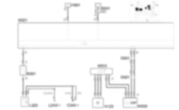
Wiring Diagram - COMPRESSOR ENGAGEMENT - Fiat ULYSSE 2.2 16V JTD fino a 04/03
Components - COMPRESSOR ENGAGEMENT - Fiat ULYSSE 2.2 16V JTD fino a 04/03
| Component code | Description | Reference to the assembly |
| Engine compartment junction unit | 5505A |
| Passenger dashboard earth | - |
| Earth on engine | - |
| Front/dashboard coupling | - |
| Instrument panel | 5560B |
| Frost sensor | 5040B |
| Linear sensor (for climate control) | - |
| Air conditioning compressor engagement electro-magnet | 5040A |
| Body computer | 5505A |
| Engine management control unit | 1060G |
| ABS control unit | 3340A |
| Climate control sytem control unit | - |
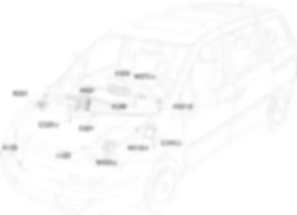
Location Components - COMPRESSOR ENGAGEMENT - Fiat ULYSSE 2.2 16V JTD fino a 04/03
Components - COMPRESSOR ENGAGEMENT - Fiat ULYSSE 2.2 16V JTD fino a 04/03
| Component code | Description | Reference to the assembly |
| B001 | Engine compartment junction unit | 5505A |
| C020 | Passenger dashboard earth | - |
| C040 | Earth on engine | - |
| D001 | Front/dashboard coupling | - |
| E050 | Instrument panel | 5560B |
| K086 | Frost sensor | 5040B |
| K120 | Linear sensor (for climate control) | - |
| L020 | Air conditioning compressor engagement electro-magnet | 5040A |
| M001 | Body computer | 5505A |
| M010 | Engine management control unit | 1060G |
| M050 | ABS control unit | 3340A |
| M070 | Climate control sytem control unit | - |
Operational Description - COMPRESSOR ENGAGEMENT - Fiat ULYSSE 2.2 16V JTD fino a 04/03
The compressor activation control is given by pressing the key housed on the climate control unit M070. The request is forwarded via CAN from pins 8, 14 connector A of control unit M070 to body computer node M001 at pins 8, 10 connector D.The control unit M070 communicates compressor engagement information to the instrument panel E050 at pins 2 and from there to the various displays.The diesel version signal is sent to pin 10 of the instrument panel E050.The command is also sent, from the body computer M001, pin 2, 4 connector M, via the CAN, to the engine management control unit M010, to pins A3, A4 connector A.Engine control unit M010 determines compressor activation or deactivation according to data supplied by linear sensor K120 connected at pins F2, H2 and F4 connector B.Compressor L020 is engaged by body computer node M001 from pin 7 connector B via junction unit B001 from pin 13 connector C at pin 7 connector B.The frost sensor K086 is connected to pins 17 and 18 of connector M from the body computer node M001, informing whether the evaporator temperature is too low; the information reaches the control unit M070 from M001 via the CAN.Description - COMPRESSOR ENGAGEMENT - Fiat ULYSSE 2.2 16V JTD fino a 04/03
To increase protection against theft attempts, an engine immobilizer system known as the CODE is used.Each time the ignition key is turned to position S, the CODE system deactivates the engine management electronic control unit functions.Each time the key is turned to position M, the CODE system sends the engine management control unit a recognition code to deactivate the immobilizing function.The keys are equipped with an electronic Transponder device that sends a coded signal to a special control unit (incorporated in the Body Computer): if it recognizes the code sent, it allows the engine to be started.The code used in the dialogue, that takes place via an aerial coaxial to the ignition switch, varies each time the engine is started (rolling code): therefore the code cannot be reproduced even using electronic scanners.The main function of the Code control unit is to recognize the key inserted in the ignition switch: it contains the secret code used in the dialogue with the key transponder. All the codes for the enabled keys and the code used in the dialogue with the engine management control unit are contained in the unit: when the key is turned to the ON position for the first time, if the key is correctly recognized, this code is transferred to the engine management control unit which remains indelibly linked to the Code unit and therefore to the Body Computer.The dialogue between the two units takes place via the two-way serial line.The function also includes the display of the status by means of the CODE warning light in the instrument panel, connected via the CAN, coming on.
| Component code | Description | Reference to the assembly |
| B001 | Engine compartment junction unit | 5505A |
| C020 | Passenger dashboard earth | - |
| C040 | Earth on engine | - |
| D001 | Front/dashboard coupling | - |
| E050 | Instrument panel | 5560B |
| K086 | Frost sensor | 5040B |
| K120 | Linear sensor (for climate control) | - |
| L020 | Air conditioning compressor engagement electro-magnet | 5040A |
| M001 | Body computer | 5505A |
| M010 | Engine management control unit | 1060G |
| M050 | ABS control unit | 3340A |
| M070 | Climate control sytem control unit | - |
ENGINE COMPARTMENT JUNCTION UNIT
B001A
B001A
B001A
B001B
B001B
B001B
B001B
B001B
B001B
B001B
B001C
B001C
B001C
B001C
B001C
B001C
B001C
B001D
B001D
B001D
B001E
B001E
B001F
B001F
B001F
B001F
B001G
B001G
B001G
B001G
B001G
B001G
B001G
PASSENGER SIDE DASHBOARD EARTH
C020A
C020A
C020B
C020B
C020C
C020C
C020D
C020D
C020E
C020E
C020F
C020F
EARTH ON ENGINE
C040A
C040A
C040A
C040A
C040A
C040A
C040B
C040B
C040B
C040B
C040B
C040B
FRONT/DASHBOARD COUPLING
D001
D001
D001
D001
D001
D001
D001
INSTRUMENT PANEL
E050
E050
E050
E050
FROST SENSOR
K086
K086
K086
LINEAR SENSOR FOR FANS
K120
K120
K120
K120
AIR CONDITIONING COMPRESSOR ENGAGEMENT ELECTRO-MAGNET
L020
L020
L020
L020
L020
BODY COMPUTER
M001A
M001A
M001B
M001B
M001B
M001B
M001B
M001C
M001C
M001D
M001D
M001D
M001D
M001E
M001E
M001E
M001F
M001F
M001F
M001F
M001G
M001G
M001H
M001H
M001I
M001I
M001L
M001L
M001L
M001L
M001M
M001M
M001M
M001M
M001M
ENGINE MANAGEMENT CONTROL UNIT
M010A
M010A
M010A
M010A
M010A
M010A
M010A
M010A
M010A
M010A
M010A
M010B
M010B
M010B
M010B
M010B
M010B
M010C
M010C
M010C
M010C
M010C
M010C
ABS CONTROL UNIT
M050
M050
M050
M050
M050A
M050A
M050A
M050A
M050B
CLIMATE CONTROL SYSTEM CONTROL UNIT
M070A
M070A
M070B
M070B
M070B
M070B
M070C
M070C
M070C
M070C


