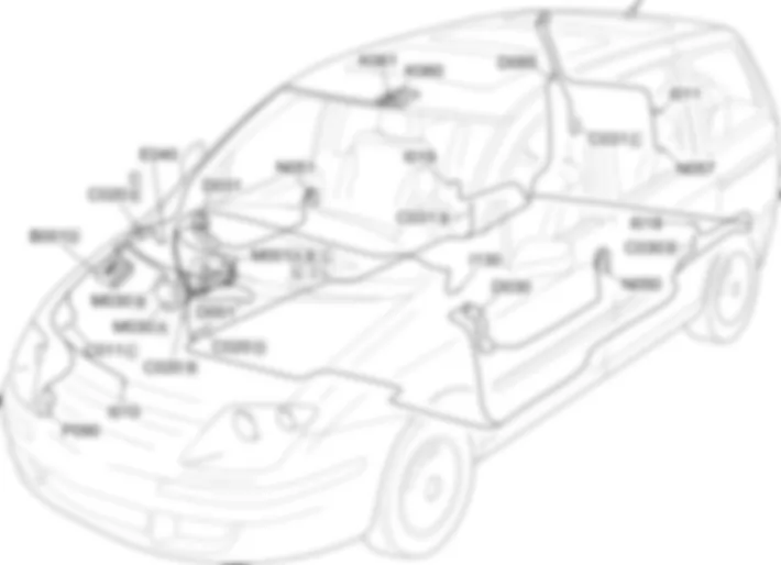
Components - ALARM - Fiat ULYSSE 2.2 16V JTD fino a 04/03
| Component code | Description | Reference to the assembly |
| B001 | ENGINE COMPARTMENT JUNCTION UNIT | Op.5,505AMULTIFUNCTION COMPONENTS |
| C011 | RIGHT FRONT EARTH | - |
| C020 | PASSENGER SIDE DASHBOARD EARTH | - |
| C030 | LEFT REAR EARTH | - |
| C031 | RIGHT REAR EARTH | - |
| D001 | FRONT/DASHBOARD COUPLING | - |
| D030 | DRIVER''S FRONT DOOR COUPLING | - |
| D031 | PASSENGER FRONT DOOR COUPLING | - |
| D085 | REAR/TAILGATE COUPLING | - |
| E040 | ALARM LED | - |
| I010 | BONNET RELEASE SWITCH | - |
| I011 | BOOT RELEASE SWITCH | |
| I018 | SWITCH ON LEFT REAR DOOR | - |
| I019 | SWITCH ON RIGHT REAR DOOR | - |
| I130 | VOLUMETRIC SENSORS DISABLING SWITCH | - |
| K060 | VOLUMETRIC SENSOR FOR LEFT ALARM | - |
| K061 | VOLUMETRIC SENSOR FOR RIGHT ALARM | - |
| M001 | BODY COMPUTER | Op.5,505AMULTIFUNCTION COMPONENTS |
| M030 | ALARM CONTROL UNIT | - |
| N050 | LEFT FRONT DOOR LOCK GEARED MOTOR | - |
| N051 | RIGHT FRONT DOOR LOCK GEARED MOTOR | Op. 7005N FRONT DOOR CENTRAL LOCKING SYSTEM |
| N057 | BOOT LOCK GEARED MOTOR | - |
The vehicle is equipped with an electronic alarm with perimeter (exterior) and volumetric (interior) protection.The alarm is switched on/off using the remote control incorporated in the key.The remote control incorporated in the key has 4 buttons:- one for activating the central locking (locking) command, switching on the alarm and the location function;- one for activating the release of the central locking and switching off the alarm.- one for opening/closing the right sliding side door;- one for opening/closing the left sliding side door.A dedicated control unit monitors the following:- the state of the doors and lids, via switches in the catches (perimeter control)- the presence of a moving object inside the passenger compartment, by means of volume-sensing sensor (volumetric control)- the condition of the system supply leads;- operation of the ignition switch.The control unit is equipped with an autodiagnostic function which detects and memorizes faults and problems in the actual control and the system components; in addition, it checks the condition of the connecting cables and memorizes the number of activations and times the alarm has been operated.The control unit operating logic can be modified in order to satisfy the legal requirements which govern the use of alarm systems in the various markets.All the outside components are connected by means of a dedicated serial line.The alarm siren is located at the front, on the left of the engine compartment.The deterrent LED is located on the right side of the dashboard: with the alarm on the LED flashes at 0.8 [Hz] to indicate that the vehicle is locked (dissuasion function).The door lock system switches are used to monitor the doors and boot.A special separate switch detects bonnet closure.The volumetric sensors check that there are no intrustions in the vehicle. Located in the front courtesy light, they consist of a transmitter and a receiver: the wave transmitted by one transmitter must reach the receiver of the other sensor and viceversa: otherwise an alarm signal is sent to the control unit.767
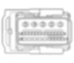
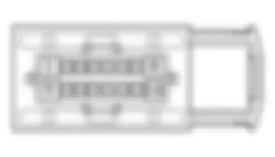
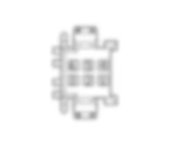
Alarm control unit M030 is supplied (pins 4 and 7 of connector A) from body computer M001 (pins 2 and 1 connector C respectively) which which it communicates (pins 10 and 12 connector A) via the CAN line (pins 4 and 6 connector C respectively).When the alarm system is activated, control unit M030 (pins 1, 4 and pins 3, 6 of connector B respectively) activates volumetric sensors K060 (pins 1, 2) and K061 (pins 1, 2).These sensors may be cut out when control unit M030 (pin 5 connector A) receives an earth signal from switch I130 (pin 6).Control unit M030 manages (pin 11 connector A) deterrent led E040 (pin 1) and monitors (pin 9 connector A) bonnet lid switch I010 (pin 1).Front catches N050, N051 (pin 1 or pin 6 if the door lock is fitted with child safety catch) communicates door open/closed status to body computer M001 (pins 4 and 5 connector L respectively).The opening of the sliding side doors is signalled (pin 1) by the specific switches I018 (left) and I019 (right) to the body computer M001 (pins 34 and 33 connector L respectively).Electric boot lock N057 is commanded (pin 1) from body computer M001 and also sends (pin 3) a boot lid closure signal (pin 13 connettore L).The signal coming from the boot lid switch I011 (pin 1) is also transmitted to the Body computer node M001 (pin 10 connector I).Alarm siren control unit P090 is supplied (pin 3) from body computer node M001 (pin 10 connector B) and receives (pin 2) an activation signal from control unit M030 (pin 2 connector A). The siren is activated even if it is not supplied with power via an internal buffer battery.Alarm system activation is indicated by activation of the turn signals (pin 11 connector B, pins 3, 5 connector G of M001).


